Transactions of the 17th International Conference on Structural Mechanics in Reactor Technology (SMiRT 17) Prague, Czech Republic, August 17 –22, 2003
Paper # J02-1
A Study on the Temperature Distribution of a Cylindrical Structure with
Multiple Holes
Young-Shin Lee1), Young-Hwan Kang2), Young-Jin Choi1) , Woong-Joong Lee1) 1) Chungnam National University, Korea
2) Korea Atomic Energy Research Institute(KAERI), Korea
ABSTRACT
This study is conducted to formulate the general solution for the temperature distribution of a cylindrical structure with multiple holes. For the temperature distribution analysis, the two-dimensional heat conduction theory is used. To show the validity of the formulation for temperature distribution of a cylindrical structure with multiple holes, it is also performed by using the commercial finite element analysis code, ANSYS 5.6. The analytical result for a cylindrical structure with multiple holes is presented and compared with a finite element result. From the analysis results, the discrepancy between finite element results and analytical results is a maximum 12% for the most part of the cylindrical structure with multiple holes
INTRODUCTION
During the fuel irradiation test in the reactor, all components of the cylindrical structure with multiple holes act like heat sources due to high gamma heat and fission heat. The objective of this study is to make an estimating model as a formulation of the general solution for the temperature distribution of a cylindrical structure with multiple holes used in the irradiation test.
FUNDAMENTAL EQUATION
1. Fundamental Equation and Boundary Conditions
Fig.1 shows the geometry and definition of the coordinates of analysis model used in this study. The coordinates (R, θ) with the origin at the cylindrical structure and (ρ, φ) with the origin at the fuel rods are used. The cylindrical structure is assumed have m fuel rods. The coolant temperature of the outer tube is uniform. The heat generation density of all components of the cylindrical structure is uniform and the heat generation rates of the fuel rods are equal. The center of the fuel rods is located at equal distances on a concentric circle of the cylinder.
Fig.1 Analysis model cylindrical structure with mutiple holes
) (1) , ( '' ' 1 1 2 2 2 2 2 θ
θ Q r
T r r T r r T
k =−
∂ ∂ ⋅ + ∂ ∂ ⋅ + ∂ ∂
Let the thermal conductivity k and the heat generation density of the holder be constant (k=const., (const.))[1~3] '' ' Q '' ' ) , ( ''
' r q Q θ =
We set boundary conditions as
(1) There are heat generators in the fuel rods arranged at equal distances on a concentric circle. They are assumed to have equal linear heat rate P. [1~3]
P d R T k i Ri = ∂ ∂ − =
∫
φ ρ π 20 ( ) r
(2)
(2) Circumferential heat flux is zero at the azimuth of of the fuel rods of number m and the heat flux is symmetry from . [1~3]
m
/
π
±
m
/
π
±
0 1 / = ∂ ∂ ⋅ − ± = m T r k π θθ (3) (3) The coolant temperature Twaround the outer tube of the cylindrical structure is assumed to be constant.
Solution of Eq. (1) under above boundary conditions is expressed in the following form.
) , ( ) cos( 2 ) / ( ) cos( 2 ln ) ( 4 '' ' ) ,
( 2 2 2
1 2 1 2 2 2 2
1 θ θ
θ
θ G r
m r a a r R a R m r a a r C r R k q r
T m m m m m m
m m m m + − + + − + + −
= (4)
Where C is an integral constant and G is a boundary function to satisfy the boundary condition.
The following assumptions are used in order to determine the boundary function G(r,θ) of Eq.(4) (1) The heat transfer coefficient of all components and the coolant temperature is uniform. (2) Circumferential heat flow in all components of the cylindrical structure can be neglected.
Applying the above assumptions and yields:
w (5)
w q R T
T R
G( 1,θ)− =α ''( 1,θ)−∆
where
f o
g
s Rh
R R R k R R R k R R R k R 4 1 3 4 1 2 3 1 1 2
1ln( / )+ ln( / )+ ln( / )+
=
α (6)
1 ) , ( '' 1 R r r T k R q = ∂ ∂ − =
θ (7)
) (8) '' '' ( 2 1 2 ln '' ) '' '' ( 2 1 2 4 4 2 1 2 2 2 oi oo f o o si si so f s s
w R q q
k k R R R q q q R k k R
T −
+ + − − + = ∆ α α 2 2 1 2 '' ' '' R q R q si π π
= s ,
2 2 2 2 '' ' '' R q R q so π π
= s ,
4 2 3 2 '' ' '' R q R q o oi π π = , 4 2 4 2 '' ' '' R q R q o oo π π = , f f h 1 =
α (9)
Differentiating Eq.(4) and substituting it into (5), we obtain
w R r m m m m m m w T r G ak m r a a R a R R ak mC R R q T R
G =∆
∂ ∂ − − + − − = − = 1 ) cos( 2 ) / ( 2 2 '' ' ) ,
( 2 2
1 2 2 1 1 1 2 1
1θ α θ (10)
The constant C is determined by the boundary condition of the inside the holder. Rewriting Eq. (2) by use of Eq. (4)
1 2 1 2 2 1 2 1 2 2 2 2 1 2 '' ' ) cos( 2 ) / ( ) cos( 2 ln ) ( 4 '' ' ) , ( R R q m r a r R a R m r a a r C r R k q r
T m m mm mm m m m α
θ θ θ + − + − + + − = w
T (11)
w n nm nm T nm R r R k nm aR R k
mC + +∆
+ + −
∑
∞ =1 1 1 11 ( / ) cos( )
The boundary conditions are represented as follows: P mR R m q d R r T k a R r m
m ∂ = − +
∂ −
= −
∫
'''( 2 2)1 1 / / 1 π π θ π π (12)
Differentiating Eq.(11) and substituting it into (12), we obtain the constant C.
) (13) '' ' ( 4 1 2 π P R q k
C= a−
We can obtain the temperature distribution of the holder by substituting Eq.(13) into Eq.(11)
av m m m m m m m m m a q m r a r R a R m r a a r k q R r R k q r T '' ) cos( 2 ) / ( ) cos( 2 ln 2 '' ) ( 4 '' ' ) ,
( 2 2
1 2 1 2 2 1 2 2
1 θ α
θ θ + − + − + + − = w
T (14)
w n
nm nm
a r R nm T
R k nm
aR q
m + +∆
+
−
∑
∞=1
1 1
1 ( / ) cos( ) / 1 ) ( '' 2 θ α α where a, av q mq
q'' = ''1− ''
1 2 2 '' ' '' R P q R q a a π π − = , pl c i a
cl R R Rq
q
P=π ''' ( 2− 2)+π 2 '''
In this study, the one-dimensional steady-state heat conduction equation is applied in order to obtain Eq.(14), the temperaure of cladding surface.
) (15) ( '' ' 1 2 2 r Q r T r r T
k =−
∂ ∂ ⋅ + ∂ ∂
We can obtain the temperature of cladding surface by substituting Eq.(16).
(
)
(
)
−(
)
− − + = c i hg c i hg i a cl i a ci c i hg c pl R R H k R R k R R q R R k R R H k R q T / ln 2 1 / ln 2 ( '' ' ) / ln( 2 / ln 2 ''' 2 2 2
1 (16)
where ) / ln( 2 ) / ln( 2 i a ci c i hg R R k R R k
H= +
NUMERICAL CALCULATIONS AND FINITE ELEMENT ANALYSIS
1. Dimensions and Material Properies of Analysis model
This study is conducted for the calculation of the temperature of a cylindrical structure with three fuel rods. Fig.2 shows the boundary condition of the analysis model. The analysis model is made to be a 1/6 model of the cylinder in consideration of the axis symmetry. The boundary condition at the outside of the outer tube is the forced convection. The analysis program uses the finite element analysis code, ANSYS 5.6. The element used for temperature analysis is the PLANE 78. Table 1 shows the dimensions of the analysis model used in the numerical calculations and the finite element analysis. The material and thermal properties of the analysis model are presented in Table 2.
Table 1 Dimensions of the cylindrical structure with multiple holes
Descriptions Symbol Dimension (mm)
Radius of pellet Rc 5.275
Inner radius of cladding Ri 5.320 Outer radius of cladding Ra 6.210 Distance between capsule and pellet a 14.500 Inner radius of support tube R1 21.220 Outer radius of support tube R2 22.520 Inner radius of support tube R3 22.650 Outer radius of support tube R4 24.150
Table 2 Mechanical and thermal properties of the cylindrical structure with multiple holes
Material
Young's modulus (GPa)
Mass density (kg/m3)
Poisson's ratio
Thermal conductivity
(W/m ·•)
Thermal expansion coeff.(W/•)
Heat generation ratio (MW/m3 )
SUS316 197 8000 0.30 14.00 16×10-6 13.26 Pellet 69 2700 0.33 2.15 0 462.60
NaK 0 800 0 27.00 0 1.22
2. Analysis Result and Discussion
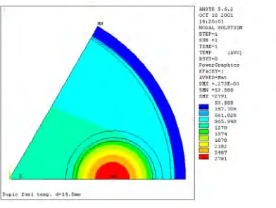
This study assumed that the coolant flows outside of the cooled outer tube. The convection and irradiation were neglected in the gap. Fig.3 shows the analysis result of the temperature of a cylindrical structure with multiple holes. The highest temperature of the fuel rod is 2635°C. and the outside temperature of the outer tube is 53.6°C. Due to the effect of the coolant, the heat flux of the outer tube direction(φ=180o) is smaller than the center direction heat flux of center direction(φ=0o) for a cylindrical structure with multiple holes. Therefore, the highest temperature of the fuel rod does not occur in the center of the fuel rod.
Fig.3 Temperature distribution of the cylindrical structure with multiple holes
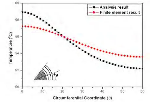
Fig.4 and Fig.5 show the comparision of the numerical and finite element results for the temperature variation of the radius direction(θ=0o,θ=60o) of the analysis model. The temperature of the cylindrical structure is transformed by the thermal conductivity size of the material. The temperature variation of the holder and cladding is not great, but the temperature variation of the the support tube and the outer tube such as cladding’s thermal conductivity changes sharply due to the effect of the coolant.
element result at the φ=0o direction of the cladding. But the temperature of the analysis result at the φ =180o of the cladding shows high tendency. The temperature differences between the analysis result and the finite element result are almost equal at the outside and inside of the cladding. Both temperature differences are the same because heat flux is equal at the outside cladding. Fig.8 shows the temperature variation of the pellet. The temperature variation between the fuel rod and the cladding is the same. The analysis results and the finite element result is equal at the φ=110o. The temperature error at the fuel rod occurred due to the temperature error generated at the holer calculation. In the temperature results of the fuel rod and the cladding, the point that the analysis result and finite element analysis result agree looks tendency that the θ increases gradually move to the center direction of construction. Fig.9 and Fig.10 show the comparision of the numerical results and the finite element results of the temperature for the radius direction(θ=0o,θ =60o) of the support tube. The analysis result and the finite element result of the temperature for the support tube like Fig.6 and Fig.7 is different than the temperature result because the result of the holder calculation has a temperature difference. Fig.11 and Fig.12 show the comparison of the analysis result and the finite element result for the temperature of the radius direction(θ=0o,θ =60o) of the outer tube. The analysis result and the finite element result look similar tendency by the boundary condition. And the temperature error at the support tube and outer tube are decreased by the coolant. In the temperature results of the support tube and the outer tube, the point that analysis result and finite element analysis result agree looks tendency that the φ decreases gradually move to center direction of construction.
Fig.4 Comparison of radial(θ=0°) temperature on the cylindrical structure with multiple holes from analysis results and finite element results
Fig.6 Comparison of cladding outside temperature on the cylindrical structure with multiple holes from analysis results and finite element results
Fig.5 Comparison of radial(θ=60°) temperature on the cylindrical structure with multiple holes from analysis results and finite element results
Fig.8 Comparison of pellet surface temperature on the cylindrical structure with multiple holes from analysis results and finite element results
Fig. 10 Comparison of support outer surface temperature on the cylindrical structure with multiple holes from analysis results and finite element results
Fig.12 Comparison of outer tube outer surface temperature on cylindrical structure with multiple holes
Fig.9 Comparison of support inside temperature on the cylindrical structure with multiple holes from analysis results and finite element results
CONCLUSIONS
1) The analytical results and finite element results for a cylindrical structure with mutlple holes show good agreement. 2) The temperature of the cylindrical structure is obtained by the finite element method and is higher than analytical results for φ=0o and lower than analytical results for φ=180o. For the temperature of the support tube and the outer tube located in a concentric circle, the finite element results are lower than analytical results on θ=0o, and higher than analytical results on θ=60o.
3) The heat flux for the cladding, support tube and outer tube of a cylindrical structure with mutlple holes is governed by the heat flux in the radial direction.
[NOMENCLATURE]
a
Distance between capsule and pelletf
h
Convection heat transfer coefficientk
,k
o,k
g Thermal conductivity of the cylindrical structurehg
k
,k
cl,k
pl Thermal conductivity of the fuel pinP
Linear heat rate of sample inserted in the sample hole''
'
q
,q
'
''
o,q
'
''
s Heat generation per unit volume of the cylindrical structurecl
q
'
''
,q
'
''
pl Heat generation per unit volume of fuel pin1
R
,R
2,R
3,R
4 Radius of the cylindrical structurec
R
,R
i,R
a Radius of the fuel rod1
T
,T
2,T
3,T
4 Temperature of the cylindrical structure∞
T
Coolant temperature around outer tube surface of the cylindrical structureα
Inverse of overall heat transfer coefficient for the support tube and the outer tubeθ
,
r
Cylindrical coordinate with origin at the center holderφ
ρ,
Cylindrical coordinate with origin at the fuel pinREFERENCE
1. Y. Harayama, 1974, “Calculate Effect of Radially Asymmetric Heat Generation on Temperature and Heat Flux Distribution in a Fuel Rod", Nuclear Engineering and Design, Vol. 31, pp. 66•71.
2. Y. Harayama and M. Kyoya, 1986, “Analysis of Effect Eccentric Holes in Pellets on Temperature and Heat Flux Distribution in Fuel Rod", Journal of Nuclear Science and Technology, Vol. 23, No. 2, pp.151•159.
3. Y. Harayama, H. Someya and T. Hoshiya, 1991, “Effect of Eccentric Pellet on Gap conductance in Fuel Rod", Journal of Nuclear Science and Technology, Vol. 28, No. 10, pp.961•964.
4. F. Kaminaga, S. Sato and Y. Okamoto, 1991, “Evaluation of Gap Heat Transfer between Boron Carbide Pellet and Cladding in Control Rod of FBR", Journal of Nuclear Science and Technology, Vol. 29, No. 2, pp.121•130.
5. Y. Harayama, T. Hoshiya, H. Someya, M. Niimi and T. Kobayashi, 1993, “Estimation for Temperature Distribution in a Heat-Generating Cylinder with Multiple Hole", Journal of Nuclear Science and Technology, Vol. 30, No.4, pp. 291•
301.
6. T. Furukwa, N. Noda and F. Ashida, 1990, “Generalized Thermoelasticity for an Infinite Body with a Circular Cylindrical Hole", JSME International Journal, Series •, Vol. 33, No. 1, pp. 26•32.
7. T. Furukwa, N. Noda and F. Ashida., 1991, “Generalized Thermoelasticity for an Infinite Solid Cylinder", JSME International Journal, Series •, Vol. 34, No. 3, pp. 281•286.
8. T. R. Hsu, 1970, “Transient Thermal Stresses on a Finite Disk due to a Continuous Point Heat Source", Journal of Engineering for Industry, AECL-3540.