Volume 2010, Article ID 467150,13pages doi:10.1155/2010/467150
Research Article
Multiharmonic Frequency Tracking Method Using
The Sigma-Point Kalman Smoother
Sunghan Kim,
1Anindya S. Paul,
2Eric A. Wan,
2and James McNames
11Biomedical Signal Processing Laboratory, Portland State University, Portland, OR 97207-0751, USA
2Department of Science and Engineering, Oregon Health and Science University (OHSU), Beaverton, OR 97006, USA Correspondence should be addressed to Sunghan Kim,[email protected]
Received 28 May 2009; Revised 17 November 2009; Accepted 2 February 2010
Academic Editor: Sangjin Hong
Copyright © 2010 Sunghan Kim et al. This is an open access article distributed under the Creative Commons Attribution License, which permits unrestricted use, distribution, and reproduction in any medium, provided the original work is properly cited.
Several groups have proposed the state-space approach to tracking time-varying frequencies of multiharmonic quasiperiodic signals. The extended Kalman filter/smoother (EKF/EKS) is one of the common frequency tracking approaches seen in the literature. We introduce a multiharmonic frequency tracker based on the forward-backward statistical linearized Sigma-Point Kalman smoother (FBSL-SPKS) and compare its performance to that of the extended Kalman smoother (EKS). In all cases the FBSL-SPKS tracker outperformed the EKS tracker over a wide range of signal-to-noise (SNR) ratios. We also demonstrate its superior performance on real signals.
1. Introduction
Many natural signals contain nearly periodic rhythms with slowly varying morphologies. Example signals with this property include tremor, speech, electrocardiogram (ECG), and arterial blood pressure (ABP). In many applications the instantaneous frequency (IF) of these signals contains useful information for further analysis.
Many signal processing methods have been applied to the problem of multiharmonic frequency tracking in quasiperi-odic signals. Especially, the pitch tracking in the speech signal analysis is one of the most common applications of multiharmonic frequency tracking. Pitch detection/tracking algorithms can be roughly categorized into three groups: time-domain methods such as zero-crossing, frequency-domain methods, and time-frequency-frequency-domain methods. All pitch tracking methods apply the frame-by-frame analysis due to the nature of human voice [1]. Recently Tabrikian et al. proposed the maximuma posteriori (MAP) probability pitch tracking method using harmonic model [2]. They implemented the MAP estimator by a dynamic program-ming procedure based on measurement collected over several frames. However, these frame-by-frame based algorithms are always not applicable especially when a local signal stationar-ity cannot be assumed. There are other methods that have
been applied to track rhythmicity (harmonic components) in nonstationary quasiperiodic signals based on adaptive schemes [3]. The advantage of using these adaptive schemes is that one can track rhythmicity (frequencies)recursivelyas signal samples are acquired.
In this paper we use a Fourier series representation, which is shown in (1) Section 2.1, of multiharmonic quasiperiodic signals in which the amplitudes, phases, and frequencies are allowed to change slowly over time. The application of state space methods to continuously track the amplitudes, phases, and frequencies was pioneered by Parker and Anderson in [4] with many subsequent investigations [5–9]. Recently there have been several proposed methods based on particle filters [10,11] which are highly computa-tionally intensive and hence practically intractable.
on a first-order Taylor series approximation of the nonlinear system around the estimate of the current state. The Sigma-Point Kalman filter (SPKF) is another generalization to nonlinear state-space models, which includes the Unscented Kalman filter (UKF) [13], Central Difference Kalman filter (CDKF) [14], and their square-root variants [15]. Like the EKF, the SPKF approximates the state distribution by a Gaussian Random Variable. The SPKF uses a deterministic sampling approach to approximate the probability density of the state-error and noise covariances by a set of carefully chosen sample points known as points. These sigma-points are chosen in such a way that they completely capture the mean and covariance of the corresponding densities. These sigma-points are then propagated through the true nonlinear system, with the posterior mean and covariance estimated using simple weighted averaging. This approach captures the posterior mean and covariance accurately to the 2nd order (3rd order is achieved for symmetric distributions) compared to EKF which only achieves 1st-order accuracy. Another advantage of the SPKF over other Kalman generalizations is that it maintains the same order of computational complexity as the EKF.
The Kalman smoother (KS) is a noncausal version of the KF. Typically, smoothers can achieve better estimates than filters since they deal with more measurements with proper design. We proposed a tremor frequency tracking method utilizing the extended Kalman smoother (EKS) in [16,17]. However, we are unaware of any literature that investigates the estimation accuracy of smoothers in the multiharmonic frequency tracking application.
Forward-backward statistical linearized sigma-point Kalman smoother(FBSL-SPKS), which is recently proposed in [18], presents a new formulation for nonlinear smoothing using Sigma-Point Kalman filtering method. The derivation of the FBSL-SPKS is obtained by making use of the relationship between the SPKF and weighted statistical linear regression (WSLR). WSLR takes into account both the mean and covariance of the prior distribution to pseudolinearize the nonlinear dynamics. Therefore, it is more accurate than the first-order Taylor series-based linearization approach, which completely neglects the prior covariance at the point of linearization. In [18], the FBSL-SPKS is shown to obtain superior estimates than the EKS in general. To our best knowledge, however, the head-to-head performance comparison between the EKS and SPKS has not been made explicitly for the multiharmonic frequency tracking application. Especially, FBSL-SPKS has never been applied to any practical applications such as multiharmonic frequency tracking.
The first objective of our study was to implement two multiharmonic frequency trackers utilizing the EKS and FBSL-SPKS and demonstrate their feasibility of tracking the frequency of multiharmonic signals. The second objective was to compare the performance of the EKS and FBSL-SPKS trackers based on the Monte Carlo simulations and real biomedical signals. We used three performance metrics to quantify different aspects of the multiharmonic tracking performance. We only examined the smoothers since our
work was focused on an offline analysis of prerecorded signals.
2. Methodology
We apply two nonlinear smoothing schemes using the EKF and SPKF approaches for multiharmonic frequency tracking problem. The EKF-based smoother, that is, the EKS, has many mathematically equivalent expressions. Here, we use a variant similar to that developed in [19] (see [20, page 374]). The nonlinear SPKF-based smoother was derived from the first principle in [18] and is referred as the FBSL-SPKS. The FBSL-SPKS is a fixed interval smoother, which uses two independent forward and backward filters for smoothing. The standard SPKF is used as a forward filter. The backward filter requires the inverse dynamics of the forward filter. While the EKS can easily invert the Taylor series based linearized dynamics, the SPKS requires a new approach to linearize the forward nonlinear dynamic model. There are two major variants of SPKS available in the literature which can solve this problem in a roundabout way. In [21], the inverse dynamic model was learned from the data by training a backward nonlinear predictor (e.g., neural network). The major disadvantages of this method are that it is application and data specific and requires a learning phase. Recently an Unscented Rauch-Tung-Striebel- (URTSS-) based smoother was proposed in [22], where a joint distribution of the current and future state is maintained in order to smoothen the current state. This method requires more computation due to doubling of the state dimension.
The FBSL-SPKS introduced a direct and straightforward formulation for forward-backward smoothing [18]. Instead of learning a backward dynamical model from the data, the proposed smoother (FBSL-SPKS) makes use of weighted statistical linear regression (WSLR) formulation of SPKF (see [18] for details). WSLR is a linearization technique that takes into account the uncertainty of the prior random variable when linearizing the nonlinear model. In this way, WSLR is more accurate in the statistical sense than the first-order Taylor series-based linearization employed by the EKF which only considers the mean of the prior densities while linearizing. By representing the forward nonlinear dynamics in terms of WSLR, a linear backward filter was derived from first principle in [18]. The forward and backward estimates were then statistically combined to obtain a smoothed estimate. This newly proposed FBSL-SPKS performed comparably with the smoothers presented in [21,22] but with higher computational efficiency and ease of implementation.
2.1. State Space Model. We use boldface notation to denote random processes, normal face for deterministic parameters, upper case letters for matrices, lower case letters for vectors and scalars, and subscripts for time indices. The observed signal is denoted asynwheren=0,. . .,Nrepresent discrete time.
phases, and frequencies are allowed to change slowly over time. It can be expressed as
yn=sn+vn
=h(xn) +vn
=
m
k=1
ak,ncos(kθn) +bk,nsin(kθn) +yn+vn, (1)
where m is the number of the harmonics assumed to be known, θn the instantaneous angle, ak,n and bk,n the amplitudes of thekth harmonic sinusoidal components,yn
the trend ofyn, and vnis a white noise process with zero-mean and variancer. The instantaneous angleθis modeled as
θn= n
i=1
2πTsfi= n
i=1
2πTs
ξi+ f
=
n
i=1
2πTsξi+ n
i=1
2πTsf =φn+ 2πTsn f,
(2)
where f is the mean frequency,ξnis the difference between the instantaneous frequencyfnand the mean frequencyf,φn the accumulative sum ofξn, andTsthe sample interval. This
is one of the major differences between our state-space model and the one proposed in [4]. This modification was necessary because the FBSL-SPKS requires the state variables to have zero mean. Sinceφnis the accumulative sum ofξn=fn−f, its mean is zero. This increases numerical stability and makes it easier to invert the model for the backward filter.
Each state-space variable was modeled as follows:
φn+1=φn+ 2πTsγn+uφ,n,
γn+1=αγn+ (1−α)uγ,n,
ak,n+1=ak,n+ua,n,
bk,n+1=bk,n+ub,n,
yn+1=yn+uy,n,
(3)
whereγnis the fluctuating component inφn,αan autore-gressive (AR) process coefficient of γn, and u·,n mutually uncorrelated white noise processes. A value ofα=1 results in a random walk model ofφnandα=0 results in a white noise model. The varianceqofu·,ndetermines how quickly the parameters are expected to change over time.
The state vectorxnis defined as
xn=
φn γn a1,n,. . .,am,n b1,n,. . .,bm,n yn
T . (4)
Then, the state-space model can be written as follows:
xn+1=f(xn) +un, (5)
= ⎡ ⎢ ⎢ ⎢ ⎢ ⎢ ⎢ ⎢ ⎢ ⎢ ⎢ ⎢ ⎢ ⎢ ⎢ ⎢ ⎢ ⎢ ⎢ ⎢ ⎣
x1,n+ 2πTsx2,n
αx2,n
x3,n
.. .
x2m+2,n
x2m+3,n
⎤ ⎥ ⎥ ⎥ ⎥ ⎥ ⎥ ⎥ ⎥ ⎥ ⎥ ⎥ ⎥ ⎥ ⎥ ⎥ ⎥ ⎥ ⎥ ⎥ ⎦ + ⎡ ⎢ ⎢ ⎢ ⎢ ⎢ ⎢ ⎢ ⎢ ⎢ ⎢ ⎢ ⎢ ⎢ ⎢ ⎢ ⎢ ⎢ ⎢ ⎢ ⎣
u1,n
u2,n
u3,n
.. .
u2m+2,n
u2m+3,n
⎤ ⎥ ⎥ ⎥ ⎥ ⎥ ⎥ ⎥ ⎥ ⎥ ⎥ ⎥ ⎥ ⎥ ⎥ ⎥ ⎥ ⎥ ⎥ ⎥ ⎦ , (6)
yn=h(xn) +vn, (7)
where f(·) and h(·) are the linear state transition and nonlinear observation functions, respectively.
2.2. EKS Frequency Tracker Recursions
2.2.1. Forward Updates. The filtered and predicted state estimates can be computed directly from the well-known EKF recursions, which can be found in [20]. In the recursions, the derivatives of the state transition function
fn(x) and observation functionhn(x) have to be computed as part of time-update and measurement-update equations, respectively. They can be expressed as follows.
(i) Derivative of fn(x) for time-update equations is
Fn= ∂ fn(x)
∂x
x=xn|n ,
Fn=
⎡ ⎢ ⎢ ⎢ ⎢ ⎢ ⎢ ⎢ ⎢ ⎢ ⎢ ⎢ ⎢ ⎢ ⎢ ⎢ ⎣
1 2πTss
x2,n|n
0 0 · · · 0
0 αsx2,n|n
0 0 · · · 0
0 0 1 0 · · · 0
0 0 0 1 · · · 0
..
. ... ... ... . .. ...
0 0 0 0 · · · 1
⎤ ⎥ ⎥ ⎥ ⎥ ⎥ ⎥ ⎥ ⎥ ⎥ ⎥ ⎥ ⎥ ⎥ ⎥ ⎥ ⎦ . (8)
(ii) Derivative of hn(x) for measurement-update equa-tions is
Hn= ∂hn (x)
∂x
Hn= ⎡ ⎢ ⎢ ⎢ ⎢ ⎢ ⎢ ⎢ ⎢ ⎢ ⎢ ⎢ ⎢ ⎢ ⎢ ⎢ ⎢ ⎢ ⎢ ⎢ ⎢ ⎢ ⎢ ⎢ ⎢ ⎢ ⎢ ⎢ ⎣ m
k=1
−ak,n+1|nksin(kθ) +bk,n+1|nkcos(kθ) 0
cos(θ)
.. .
cos(mθ)
sin(θ) .. .
sin(mθ)
1 ⎤ ⎥ ⎥ ⎥ ⎥ ⎥ ⎥ ⎥ ⎥ ⎥ ⎥ ⎥ ⎥ ⎥ ⎥ ⎥ ⎥ ⎥ ⎥ ⎥ ⎥ ⎥ ⎥ ⎥ ⎥ ⎥ ⎥ ⎥ ⎦ T . (9)
The further detail of the EKF recursions can be found in [20].
2.2.2. Smoothing. There are many mathematically equivalent expressions for the extended Kalman smoother (EKS). Here we use a variant similar to that developed in [19] (see [20, page 374]). The backward recursive update equations for the EKS start with initialization at timeNsuch as
ψN+1|N =0, (10)
where ψ is called the adjoint variable. The smoothed estimates can then be computed as follows.
(i) Backward-update equations are
Kp,n=
FnPn|n−1HnT
r−1
e,n,
ψn|N =
Fn−Kp,nHn
T
ψn+1|N+HnTr−e,n1en,
xn|N =xn|n−1+Pn|n−1ψn|N.
(11)
2.3. SPKS Multiharmonic Frequency Tracker Recursions. Our proposed FBSL-SPKS uses a forward-backward approach. A standard SPKF is run in the forward direction using the nonlinear model shown in (5) and (7). A backward filter then computes the estimates operating on the inverse dynamics of the forward filter. WSLR formulation as described below is used to pseudolinearize the nonlinear state-space model so that it is inverse can be computed. The forward and backward estimates are then optimally combined to generate the smoothed estimates. In order to better understand the equations of FBSL-SPKS, first we describe how SPKF performs an inherent linearization called WSLR, which considers both the mean and covariance of the prior random variable (RV) at the point of linearization.
(ii)Weighted Statistical Linear Regression (WSLR) is as follows.
Consider a prior RVx which is propagated through a nonlinear functiong(x) to obtain a posterior RVy. Sigma-pointsχi,i = 0, 1,. . ., 2M are selected as the prior meanx
plus and minus the columns of the square root of the prior covariancePx:
χ=x x+γPx x−γ
Px
, (12)
whereMis the RV dimension andγis the composite scaling parameter. The sigma-points setχ completely captures the meanxand the covariancePxof the prior RVx:
x=
2M
i=0
wiχi,
Px= 2M
i=0
wi
χi−x
χi−x
T ,
(13)
where wi is the normalized scaler weight for each sigma-point. Each prior sigma-point is propagated through the nonlinearity to form the posterior sigma-points setγi:
γi=g
χi
i=0, 1,. . ., 2M. (14)
The posterior statistics can then be calculated using weighted averaging of the posterior sigma-points,
y=
2M
i=0
wiγi,
Px= 2M
i=0
wi
γi−y
γi−y
T ,
Pxy= 2M
i=0
wi
χi−x
γi−y
T .
(15)
An alternate view is to consider the estimates arising from the sigma-point approach as a weighted statistical linearization of the nonlinear dynamics:
y=g(x)∼=Ax+b+, (16)
whereAandbare the statistical linearization parameters and can be determined by minimizing the expected mean square error which takes into account the uncertainty of the prior RVx. DefiningJ = E[TW] is the expected mean square error with sigma-point weighting matrixW:
[A,b]=arg minJ
=arg minETW. (17)
The true expectation can be replaced as a finite sample approximation:
ETW=
2M
i=0
wiT
ii, (18)
where the point wise linearization error isi=γi−Aχi−b. Now taking partial derivative onJwith respect tobwe obtain
∂J
By substitutingJwith (g(x)−Ax−b)TW(g(x)−Ax−b) the equation can be rewritten as follows:
∂g(x)−Ax−bTWg(x)−Ax−b
∂b =0.
(20)
After cross multiplication and differentiation, (20) simplifies to
EWg(x)−Ax−b=0 (21) Solving forbfrom (21) we get
b=Eg(x)−AE[x],
b=z−Ax. (22)
Substituting the value ofbobtained in (22) intoJand taking the partial derivative with respect toAwe get
∂J
∂A=0. (23)
Then, the equation can be rewritten as
∂g(x)−z−A(x−x)TWg(x)−z−A(x−x)
∂A =0.
(24)
Cross multiplication and differentiation with respect toAon (24) provides
EWAxxT+g(x)−zxT=0, (25) wherex=(x−x); solving forAfrom (25) we get
A=E(x−x)(z−z)TTE(x−x)(x−x)T−1 =PTxzP−x1,
(26)
where the prior mean (x) and covariance (Px) are calculated
in (13) from the prior sigma-points. Similarly, the posterior mean (z) and covariances (PzandPxz) are calculated from
the posterior sigma-points. The linearization errorhas zero mean and covariancePwhich is defined as follows
P=
2M
i=0
wiiT i
=
2M
i=0
wi
γi−
Aχi+bγi−Aχi+bT
=
2M
i=0
wi
γi−Aχi−z+Ax
γi−Aχi−z+Ax
T
=
2M
i=0
wi
γi−z
−Aχi−x
×γi−z
−Aχi−xT
=Pz−APxz−PTxzAT+APxAT.
(27)
ReplacingPT
xz=APxfrom(26)
P=Pz−APxAT−APxAT+APxAT
=Pz−APxAT.
(28)
From (28),Pz=APxAT+P, we observe that the covariance of the linearization error P is added when calculating the posterior covariancePz. Theuncertainty feedbackscheme is
very important especially when there is severe nonlinearity over theuncertainty region of prior RV. First-order Taylor series-based linearization employed by EKF often diverges in highly nonlinear region as it only performs linearization around the mean of the RV but neglects this error term. In general, the WSLR technique is an optimal way of linearizing any nonlinear function in the minimum mean square error (MMSE) sense as this approach explicitly takes into account the prior RV statistics (e.g., mean and covariance).
To form the SPKF estimator, we consider the nonlinear state-space model:
xn+1=fn(xn,un),
yn=hn(xn,vn),
(29)
where xn ∈ RM is the state, yn ∈ RP is the observation at time indexn,unandvnare Gaussian distributed process and observation noises, f(·) is the nonlinear dynamic model andh(·) is the nonlinear observation model function. The process and observation noise has zero mean and covariances
Qn and Rn, respectively. The SPKF is then derived by recursively applying the sigma-point selection scheme shown above at every time index to these dynamic equations (see [13] for more details).
Alternatively, we may form the statistically linearized state-space using the WSLR technique:
xn+1=Af,nxn+bf,n+Gf,nun+Gf,nf,n,
yn=Ah,nxn+bh,n+vn+h,n,
(30)
whereAf,n,Ah,n,bf,n, andbh,nare the statistical linearization parameters and f,n, h,n are the linearization error with mean zero and covariancePf,nandPh,n. All the parameters can be obtained by applying (22) and (26) iteratively at each time indexn. Deriving the KF using the linearized state-space shown in (30) also leads to SPKF (see [21]). This statistically linearized form allows to form the dynamics of the backward filter used in forward-backward smoothing approach. As the statistically linearized state space shown in (30) is different from the standard linear state space used by the Kalman filter, the detailed derivation of the FBSL-SPKS which is demonstrated in the next sections needs to be done from the first principle. The pseudocode for the FBSL-SPKS can now be specified as follows.
(i) Initialization:
x0|0=E
x0|0
,
Px0|0=E
x0|0−x0|0
x0|0−x0|0
T ,
xa
0|0=E
xa
0|0
=xT0|0 u0T|0 vT0|0T,
Pa
x0|0=
xa0|0−x0a|0xa0|0−x0a|0T
, = ⎡ ⎢ ⎢ ⎢ ⎢ ⎣
Px0|0 0 0
0 Q 0
0 0 R
⎤ ⎥ ⎥ ⎥ ⎥ ⎦. (31)
(ii) Calculation of sigma-points:
χa n|n=
xan|n xan|n+Λ xan|n−Λ, (32)
whereΛ=(L+λ)Pa
xn|n.
(iii) Time-update equations:
χx
i,n+1|n= fn
χx
i,n|n,χui,n|n
i=0, 1,. . ., 2L,
xn+1|n=
2L
i=0
w(im)χxi,n+1|n,
Pxn+1|n=
2L
i=0 2L
j=0
wi j(c)
χx
i,n+1|n−xn+1|n
×χx
j,n+1|n−xn+1|n
T .
(33)
(iv) Weighted Statistical Linearization of f(·):
Pxn|n,xn+1|n =
2L
i=0 2L
j=0
wci j
χx
j,n|n−xn|n
×χx
i,n+1|n−xn+1|n
T ,
Af,n=PTxn|nxn+1|nP −1 xn|n,
bf,n=xn+1|n−Af,nxn|n,
Pf,n=Pxn+1|n−Af,nPxn|nA T
f,n.
(34)
(v) Measurement-update equations:
γi,n+1|n=hn
χx
i,n+1|n,χvi,n|n
i=0, 1,. . ., 2L,
yn+1|n=
2L
i=0
wi(m)γi,n+1|n,
Pyn+1|n =
2L
i=0 2L
j=0
w(i,cj)
γj,n+1|n−yn+1|n
×γi,n+1|n−yn+1|n
T ,
Pxn+1|n,yn+1|n =
2L
i=0 2L
j=0
w(i,cj)
χx
j,n+1|n−xn+1|n
×γi,n+1|n−yn+1|n
T ,
Kn+1=Pxn+1|nyn+1|nP −1 yn+1|n,
xn+1|n+1=xn+1|n+Kn+1
yn+1−yn+1|n
,
Pxn+1|n+1 =Pxn+1|n−Kn+1Pyn+1|nK T n+1.
(35)
(vi) Weighted Statistical Linearization ofh(·):
Ah,n=PTxn+1|nyn+1|n
Pxn+1|n
−1
,
bh,n=zn+1|n−Ah,nxn+1|n, Ph,n=Pyn+1|n−Ah,nPxn+1|nA
T h,n,
(36)
(vii) where
xa=xT uT vTT,
χa=(χx)T (χu)T
(χv)TT ,
Pa
xn|n=
⎡ ⎢ ⎢ ⎢ ⎣
Pxn|n 0 0
0 Q 0
0 0 R
⎤ ⎥ ⎥ ⎥ ⎦. (37)
(viii)Parameters: λ is the composite scaling parameter which is given by
λ=α2(L+κ)−L (38)
wherewi(c) and w
(m)
i are the scaler sigma-point weights and they are defined as
w(0c)=
λ
(L+λ)+
1−α2+β, i=0,
w(0m)=
λ
(L+λ), i=0,
w(ic)= 1
2(L+λ), i=1, 2,. . ., 2L,
w(im)= 1
2(L+λ), i=1, 2,. . ., 2L,
where α controls the size of the sigma-point distribution and should be within 0 ≤ α ≤ 1 to avoid sampling nonlocal points when the nonlinearities are strong [21].
β≥0 is the weighting term which incorporates the higher-order moments of the prior distribution. As generally sigma-points can effectively capture the first 2 moments (mean and covariance) of the distribution (for gaussian any symmetrical sigma-points set also capture the third-order moment, i.e., skewness), the parameter β also can be used to minimize the error of higher-order moments of the distribution due to sigma-point approximation effects. For Gaussian prior,
β = 2 [13]. The parameter κ is used to make sure that the positive definiteness of the covariance matrices and the default choice ofκ ≥ 0 should work for most of the cases.
Lis the dimension of the augmented state;QandRare the process and observation noise covariances.
2.3.2. Backward Updates. An information filter is used to estimate the states from the backward direction given all the present and future measurements. As the statistically lin-earized state-space is different from the standard linear state-space used by the Kalman filter, the time and measurement update equations had to be derived from the first principle [18]. The backward filter recursion which operates on the statistically linearized state-space shown in (30) is given as fpllows.
(i) Initializations:
SN+1|N+1=0,
zN+1|N+1=0,
(40)
whereSn|n=(Pbxn|n) −1
is the information matrix and
zn|n = Sn|nxbn|n is defined as the information state. The state estimate and error covariance matrix for the backward filter can be denoted asxnb|nand (Pbxn|n), respectively.
(ii) Time-update equations:
Sn|n+1=ATf,nSn+1|n+1Af,n−ATf,nSn+1|n+1Gf,n
·Pf,n+Q
−1
+GTf,nSn+1|n+1Gf,n
−1
·GT
fSn+1|n+1Af,n.
(41)
DefineKb,nas the backward gain matrix:
Kb,n=Sn+1|n+1Gf,n
Pf,n+Q
−1
+GTf,nSn+1|n+1Gf,n
−1
.
(42)
Then,
Sn|n+1=ATf,n
I−Kb,nGTf,n
Sn+1|n+1Af,n,
zn|n+1=ATf,n
I−Kb,nGTf,n
·zn+1|n+1−Sn+1|n+1bf,n
.
(43)
Table1: Summary of user-specified design parameters.
Name Symbol Value
AR coefficient α 0.9987
Phase process noise variance qθ 10−5Ts
Frequency process noise variance qf 100Ts Amplitude process noise variance qs 0.0002Ts Average process noise variance qy 0.001Ts
Measurement noise variance r 1
Mean frequency f 100 Hz
Tsis a sample interval.
(iii) Measurement-update equations:
Sn|n=Sn|n+1+Ah,n
Ph,n+R
−1 Ah,n,
en=
yn−bh,n
,
zn|n=zn|n+1+Ah,n
Ph,n+R
−1 en.
(44)
2.3.3. Smoothing. The SPKF is run in the forward direction on the interval [0,N] to compute the forward posterior estimatesxn|n. The information filter is then run backwards to form the prior backward estimateszn|n+1. The two
esti-mates are then optimally combined to obtain the smoothed estimatexsn|nand corresponding covariancePsn|n.
Psn|n=Pxn|n
−1
+Sn|n+1
−1
,
xsn|n=I+Pxn|nSn|n+1
−1
xn|n+Psn|nzn|n+1.
(45)
3. Experiment
3.1. Synthetic Time-Variant Harmonic Signals. We generated two sets of synthetic signals with time-variant harmonics whose sample rate was fs = 2 kHz, mean frequency f =
100 Hz, and duration 3 s using (1)–(3). The first set of synthetic signals contains the rhythmicity during the entire 3 seconds duration. The second set of synthetic signals contains the rhythmicity only during the first and last one seconds, 0-1 and 2-3 seconds. Between 1 and 2 seconds the signals are simply white Gaussian noise. The second set of synthetic signals mimics those signals whose rhythmicity is intermittent.
0 0.2 0.4 0.6
Fre
q
u
en
cy
(k
H
z)
0 0.3 0.6 0.9 1.2 1.5 1.8 2.1 2.4 2.7 3 Time (s)
(a) Spectrogram of a true signal with the estimated harmonics (white lines) using the EKS frequency tracker
0 0.2 0.4 0.6
Fre
q
u
en
cy
(k
H
z)
0 0.3 0.6 0.9 1.2 1.5 1.8 2.1 2.4 2.7 3 Time (s)
(b) Spectrogram of a true signal with the estimated harmonics (white lines) using the FBSL-SPKS frequency tracker
Figure1: (a) EKS Frequency Estimate and (b) FBSL-SPKS Frequency Estimate. The black area in the spectrograms represents great power concentrated in the corresponding frequency at a given time.
0 0.2 0.4 0.6
Fre
q
u
en
cy
(k
H
z)
0 0.3 0.6 0.9 1.2 1.5 1.8 2.1 2.4 2.7 3 Time (s)
(a) Spectrogram of residuals with the EKS frequency tracker
0 0.2 0.4 0.6
Fre
q
u
en
cy
(k
H
z)
0 0.3 0.6 0.9 1.2 1.5 1.8 2.1 2.4 2.7 3 Time (s)
(b) Spectrogram of residuals with the FBSL-SPKS frequency tracker
Figure 2: (a) EKS Estimation Error (NMSE = 8.56) and (b) FBSL-SPKS Estimation Error (NMSE = 7.53). The black area in the spectrograms represents great power concentrated in the corresponding frequency at a given time. If the harmonic tracking is successful, the black stripes in Figures1(a)and1(b)should be eliminated as shown in Figures2(a)and2(b). The EKS harmonic tracker does not track the harmonic components appropriately in the rectangular box inFigure 1(a), which results in the black stripes left in the box as shown in Figure 2(a).
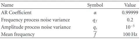
Table2: Synthetic signal generation parameters.
Name Symbol Value
AR Coefficient α 0.99999
Frequency process noise variance qf 0.2 Amplitude process noise variance qs 10−5
Mean frequency f 100 Hz
any bias incurred during the selection of the user-specified parameters would favor the EKS tracker.
The SPKS multiharmonic frequency tracker has a few of parameters that the EKS tracker does not have. Those param-eters and their chosen values are described inSection 2.3.1.
3.3. Performance Measures. There are two main issues that need to be addressed when comparing the performance of
frequency trackers: accuracy and lock-on time. The accuracy quantifies how closely the tracker estimates the state. The lock-on time is a measure of how quickly the tracker can converge to the true state.
Depending on the application, the primary objective of frequency tracking may be accurate tracking of an instanta-neous frequency or “signal denoising”. When the rhythmicity in a given signal is intermittent, it is also important that the frequency tracker can regain its track of the intermittent instantaneous frequency as quickly as possible [10].
We used three metrics to compare the accuracy and speed of the EKS and FBSL-SPKS multiharmonic frequency trackers. The first metric is the normalized mean-square-error (NMSE):
NMSE=
N n=1
sn−sn|N
2
N
n=1(sn−s)2
, (46)
0 0.1 0.2 0.3 0.4 0.5 0.6 0.7
NMSE
−2 0 2 4 6 8 10
SNR (dB) EKS
SPKS
(a) NMSE versus SNR
0 0.2 0.4 0.6 0.8 1
NFMSE
−2 0 2 4 6 8 10
SNR (dB) EKS
SPKS
(b) NFMSE versus SNR
Figure3: (a) NMSE versus SNR (b) NFMSE versus SNR. In the plots the shaded regions represent the 5th and 95th percentile ranges of the NFMSE and NMSE, respectively.
0 200 400 600 800 1000 1200
SFE
(Hz
2)
2 2.5 2.1 2.15 2.2 2.25 2.3 Time (s)
EKS SPKS
Figure 4: Convergence Speed (SFE(n) versus Time) at SNR = −3. In this figure the shaded regions represent the 5th and 95th percentile ranges of the SFE(n).
The second metric is normalized frequency mean-square-error (NFMSE):
NFMSE=
N n=1
fn−fn|N
2
N n=1
fn−f
2 , (47)
where fn is the instantaneous frequency (IF), fn is the estimated IF, and f is the mean IF. NFMSE has a natural scale ranging from 0 to 1. A value NFMSE = 1 means that the average accuracy of the estimated IF is no better than simply using the mean IF as an estimate. Values of NFMSE>1 indicate poorer frequency tracking than a simple mean estimator and those of NFMSE1 indicate accurate frequency tracking.
The third metric is the square-frequency-error (SFE(n)), which can be written as
SFE(n)=fn−fn|N
2
. (48)
When this metric is averaged over an ensemble of synthetic signals, it visualizes how rapidly the trackers lock on to the true frequency. In contrast to NMSE and NFMSE, SFE(n) is a function of time that shows the squared difference between the true IF and its estimate at a given time. For all of our results we calculated the NFMSE, NMSE, and SFE(n) over an ensemble of 300 synthetic signals.
4. Results and Discussion
4.1. Synthetic Signals. Two plots in Figure 1 show the estimated multiharmonic frequencies using the EKS (a) and FBSL-SPKS (b) trackers on top of the spectrogram of a syn-thetic signal generated using (1)–(3) whose SNR was−3 dB. At 1.1 s the EKS tracker lost track of the true frequency because the estimated third harmonic started tracking the fourth harmonic of the signal. The same situation occurred toward to the end of the signal at 2.7 s. However, the FBSL-SPKS tracker never lost its track of the true IT during the entire signal duration. Two plots inFigure 2 show the spectrograms of estimation residuals using the EKS (a) and FBSL-SPKS (b) trackers. The residual spectrogram (a) in
Figure 2depicts some harmonic structures between 1.1–1.7 s
and 2.7–3.0 s due to the estimation error of the EKS tracker.
Figure 3(a) shows NMSE versus SNR of the EKS and
0 0.2 0.4 0.6
Fre
q
u
en
cy
(k
H
z)
0 0.3 0.6 0.9 1.2 1.5 1.8 2.1 2.4 2.7 3 Time (s)
No rhythmicity
(a) EKS at SNR=−3
0 0.2 0.4 0.6
Fre
q
u
en
cy
(k
H
z)
0 0.3 0.6 0.9 1.2 1.5 1.8 2.1 2.4 2.7 3 Time (s)
No rhythmicity
(b) FBSL-SPKS at SNR=−3
Figure5: (a) Estimated frequencies using the EKS on top of an intermittent rhythmicity signal at SNR = −3. (b) Estimated frequencies using the FBSL-SPKS on top of an intermittent rhythmicity signal at SNR=−3.
0 0.2 0.4 0.6
Fre
q
u
en
cy
(k
H
z)
0 0.3 0.6 0.9 1.2 1.5 1.8 2.1 2.4 2.7 3 Time (s)
No rhythmicity
(a) EKS residuals at SNR=−3
0 0.2 0.4 0.6
Fre
q
u
en
cy
(k
H
z)
0 0.3 0.6 0.9 1.2 1.5 1.8 2.1 2.4 2.7 3 Time (s)
No rhythmicity
(b) FBSL-SPKS residuals at SNR=−3
Figure6: (a) Spectrogram of a residual signal using the EKS tracking of an intermittent rhythmical signal. (b) Spectrogram of a residual signal using the FBSL-SPKS tracking of an intermittent rhythmical signal.
0 100 200 300 400
Fre
q
u
en
cy
(k
H
z)
0 1 2 3 4 5 6
Time (s) (a) EKS
0 100 200 300 400
Fre
q
u
en
cy
(k
H
z)
0 1 2 3 4 5 6
Time (s) (b) FBSL-SPKS
0 100 200 300 400
Fre
q
u
en
cy
(k
H
z)
0 1 2 3 4 5 6
Time (s) (a) EKS residuals (NMSE=0.104)
0 100 200 300 400
Fre
q
u
en
cy
(k
H
z)
0 1 2 3 4 5 6
Time (s)
(b) FBSL-SPKS residuals (NMSE=0.038)
Figure8: (a) Spectrogram of residuals using the EKS tracking of a photosensor insect activity signal. (b) Spectrogram of residuals using the FBSL-SPKS tracking of a photosensor insect activity signal.
0 2 4 6 8 10
Fre
q
u
en
cy
(H
z)
0 5 10 15 20 25 30
Time (min) (a) EKS
0 2 4 6 8 10
Fre
q
u
en
cy
(H
z)
0 5 10 15 20 25 30
Time (min) (b) FBSL-SPKS
Figure9: (a) Estimated frequency using the EKS on top of the spectrogram of an ABP signal. (b) Estimated frequency using the FBSL-SPKS on top of the spectrogram of an ABP signal.
0 2 4 6 8 10
Fre
q
u
en
cy
(H
z)
0 5 10 15 20 25 30
Time (min) (a) EKS residuals (NMSE=0.022)
0 2 4 6 8 10
Fre
q
u
en
cy
(H
z)
0 5 10 15 20 25 30
Time (min)
(b) FBSL-SPKS residuals (NMSE=0.005).
state and error covariances with the sampling approach of the FBSL-SPKS as compared to the local linearization approach of the EKS.
Figure 4depicts the SFE(n) of the two multiharmonic
trackers. It demonstrates that on average the FBSL-SPKS tracker can regain its track of the true IF faster than the EKS tracker.
Plots in Figure 5 show the estimated instantaneous frequencies using the EKS and FBSL-SPKS trackers on top of the spectrogram of a synthetic signal whose rhythmicity is present only during 0-1 s and 2-3 s. The FBSL-SPKS tracker started tracking the true IF accurately at 2.5 s while the EKS frequency tracker failed to regain its track of the true IF. Plots in Figure 6 show the spectrograms of estimation residuals using the EKS Figure 6(a) and
FBSL-SPKS Figure 6(b)trackers. The EKS tracker barely started
tracking the true frequency toward the very end of the signal. However it took only 0.4 seconds for the FBSL-SPKS to start tracking the true frequency after the rhythmicity came back at 2 seconds.
4.2. Real Signal Examples. We applied both trackers to two different types of real signals: a photosenor insect activity signal and an arterial blood pressure (ABP) signal. The photosensor insect activity signal has a clear harmonic struc-ture, which carries important entomological information. The instantaneous frequency and the harmonic amplitudes help entomologists determine what kind of insects flew over the photosensor [23, 24]. The ABP signal also has many harmonics by nature. Accurate tracking of the harmonics in the ABP signal is critical to check a patient’s heart condition. However, the ABP signal can often be noisy due to signal drops and medical device interference. The following example will demonstrate that the FBSL-SPKS harmonic tracker is more robust to this type of noise than the EKS harmonic tracker.
The sampling frequency of the photosensor insect activ-ity signal was 16 kHz and its duration was 10s. Figures7(a) and7(b)show the estimated harmonics using the EKS (a) and FBSL-SPKS (b) multiharmonic trackers on top of the spectrogram of a photosensor insect activity signal. Figures 8(a)and8(b)are the spectrograms of estimation residuals using the EKS and FBSL-SPKS, respectively. The NMSE between the true and reconstructed bug signals using the FBSL-SPKS was 0.038 while that using the EKS was 0.104. The FBSL-SPKS tracker could track the harmonics during the entire time period while the EKS tracker lost its track between 2.3 s and 2.9 s, which is marked with two dark grey bars. The performance difference may not be apparent in Figures 8(a) and 8(b). However, the estimated harmonic frequencies between two grey bars inFigure 7(a)show that the slight error in fundamental frequency estimation results in the complete mismatch of higher harmonic frequency estimation. This result matches the simulation results shown
inFigure 3.
The ABP signal was sampled at 500 Hz and its duration was 30 minutes. Figures9(a)and9(b)depict the estimated harmonics using the EKS (a) and FBSL-SPKS (b) multi-harmonic trackers on top of the spectrogram of an arterial
blood pressure (ABP) signal. Figures 10(a) and 10(b) are the spectrograms of estimation residuals using the EKS and FBSL-SPKS trackers, respectively. Figure 9 shows a typical example of signal drops at 25 minutes, which is common in ABP signals. While the EKS tracker could not regain its track of the right frequencies after this signal drop, the FBSL-SPKS tracker was able to regain its track. This result again demonstrated that the FBSL-SPKS harmonic tracker is more reliable than the EKS harmonic tracker.
5. Conclusion
We implemented the multiharmonic tracker using the recently proposed FBSL-SPKS technique and made the head-to-head performance comparison between the FBSL-SPKS and EKS multiharmonic trackers based on synthetic and real-world signals. Using three difference performance metrics, we demonstrated that the FBSL-SPKS multiharmonic tracker is more accurate and robust to noise than the EKS multihar-monic tracker.
Acknowledgment
This work was supported in part by the Thrasher Research Fund.
References
[1] R. J. McAulary and T. F. Quatieri, “Speech analysis/synthesis based on a sinusoidal representation,”IEEE Transactions on Acoustics, Speech, and Signal Processing, vol. 34, no. 4, pp. 744– 754, 1986.
[2] J. Tabrikian, S. Dubnov, and Y. Dickalov, “Maximum a-posteriori probability pitch tracking in noisy environments using harmonic model,” IEEE Transactions on Speech and Audio Processing, vol. 12, no. 1, pp. 76–87, 2004.
[3] D. Li and R. Jung, “Tracking rhythmicity in nonstationary quasi-periodic biomedical signals using adaptive time-varying covariance,”Computers in Biology and Medicine, vol. 32, no. 4, pp. 261–282, 2002.
[4] P. J. Parker and B. D. O. Anderson, “Frequency tracking of nonsinusoidal periodic signals in noise,”Signal Processing, vol. 20, no. 2, pp. 127–152, 1990.
[5] B. James, B. D. O. Anderson, and R. C. Williamson, “Conditional mean and maximum likelihood approaches to multiharmonic frequency estimation,” IEEE Transactions on Signal Processing, vol. 42, no. 6, pp. 1366–1375, 1994. [6] B. F. La Scala, R. R. Bitmead, and B. G. Quinn, “An exteded
Kalman filter frequency tracker for high-noise environments,”
IEEE Transactions on Signal Processing, vol. 44, no. 2, pp. 431– 434, 1996.
[7] B. F. La Scala and R. R. Bitmead, “Design of an extended Kalman filter frequency tracker,”IEEE Transactions on Signal Processing, vol. 44, no. 3, pp. 739–742, 1996.
[8] S. Bittanti and S. M. Savaresi, “On the parameterization and design of an extended Kalman filter frequency tracker,”IEEE Transactions on Automatic Control, vol. 45, no. 9, pp. 1718– 1724, 2000.
[10] E. Fischler and B. Z. Bobrovsky, “Mean time to loose lock of phase tracking by particle filtering,”Signal Processing, vol. 86, no. 11, pp. 3481–3485, 2006.
[11] C. Dubois and M. Davy, “Joint detection and tracking of time-varying harmonic components: a flexible bayesian approach,”
IEEE Transactions on Audio, Speech and Language Processing, vol. 15, no. 4, pp. 1283–1295, 2007.
[12] R. E. Kalman, “A new approach to linear filtering and prediction problems,”Transactions of the ASME, vol. 82, pp. 35–45, 1960.
[13] S. J. Julier and J. K. Uhlmann, “Unscented filtering and nonlinear estimation,”Proceedings of the IEEE, vol. 92, no. 3, pp. 401–422, 2004.
[14] M. Norgaard, N. K. Poulsen, and O. Ravn, “New developments in state estimation for nonlinear systems,”Automatica, vol. 36, no. 11, pp. 1627–1638, 2000.
[15] R. van der Merwe and E. Wan, “The square-root unscented kalman filter for state and parameter estimation,” in Proceed-ings of the IEEE International Conference on Acoustics, Speech and Signal Processing (ICASSP ’01), vol. 6, pp. 3461–3464, May 2001.
[16] S. Kim and J. McNames, “Tracking tremor frequency in spike trains using the extended Kalman filter,” inProceedings of the Annual International Conference of the Engineering in Medicine and Biology Society, vol. 7, pp. 7576–7579, 2005.
[17] S. Kim and J. McNames, “Tracking tremor frequency in spike trains using the extended Kalman smoother,” IEEE Transactions on Biomedical Engineering, vol. 53, no. 8, pp. 1569–1577, 2006.
[18] A. S. Paul and E. A. Wan, “A new formulation for nonlinear forwardbackward smoothing,” inProceedings of the IEEE Inter-national Conference on Acoustic Speech and Signal Processing (ICASSP ’07), 2007.
[19] A. E. Bryson and M. Frazier, “Smoothing for linear and nonlinear dynamic systems,” Tech. Rep. TDR 63-119, Aero Systems Division, Wright-Patterson Air Force Base, Dayton, Ohio, USA, 1963.
[20] T. Kailath, A. H. Sayed, and B. Hassibi,Linear Estimation, Prentice-Hall, 2000.
[21] R. van der Merwe,Sigma point kalman filters for probabilistic inference in dynamic state-space models, Ph.D. dissertation, OGI School of Science and Engineering, Oregon Health & Science University (OHSU), 2004.
[22] S. Sarkka, “Unscented rauch-tung-striebel smoother,” IEEE Transactions on Automatic Control, vol. 53, no. 3, pp. 845–849, 2008.
[23] A. Moore, J. Miller, B. Tabashnik, and S. Gage, “Automated identification of flying insects by analysis of wingbeat frequen-cies,”Journal of Economic Entomology, vol. 79, no. 6, pp. 1703– 1706, 1986.