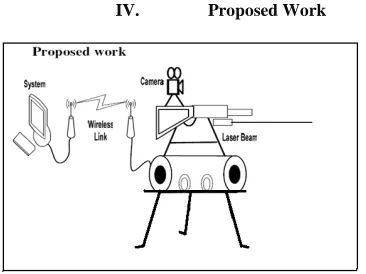
system will be a combination of the robotic controlled tank and remote operated machine gun. It uses the design of TRAP system.
Border Security System
Karthikeyan. A & Sarath Kumar.V(2012)
In this system sensor uses the concept of Black Body Radiation. If anyone tries to cross the border sensor detects and it sends a signal to The microcontroller switch on the camera which captures the image of the human and it transmit the signals to the near security station. In the receiver circuit which displays the image captured on the monitor. After sensing the image, the official can send control signal, in the border side the micro controller activate the relay driver which drives the load such as automatic function guns.
Problem Statement:
Today we use manual method for protection. i.e. by, soldiers continuously observing terror movement on actual Line Of Control which is not safe for the soldiers life, there may be human errors also which is dangerous hence to overcome these issues we have proposed a system which provides an easy solution for this by providing remote accessibility using wireless technology
III. BLOCK DIAGRAM
Block diagram of proposed system
There are two blocks, the transmitter side and the receiver side. At the transmitter side continuously monitoring from location of the machine gun will be done. And at the receiver side, the gun actions will be performed under the decisions taken by the user at control room. There is the interconnection between the transmitting and receiving ends which are properly synchronized with each other. The resonance helps in perfect matching two ends.
Transmitter Section:
Fig 1: Block diagram of the transmitter side (control
room).
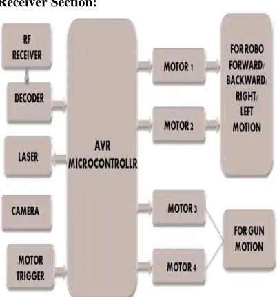
Receiver Section:
Fig 2: Block diagram of the proposed system at the
receiver side (remote unit).
Fig 6. Wireless camera
C. MACHINE GUN:
Another main unit in the system is remote controlled and auto triggered machine gun. It is situated on the basement. User can send signal to operate the gun remotely using remote input device
MACHINE GUN ROTATION:
The rotation of Gun is done by two motors. One in horizontal direction & other in vertical direction, so that user can target or see at any direction by rotating gun using remote input device.
D. JOYSTICK SWITCH
FEATURES:
- Easy to use & handling.
- Simplification of the command control station - Easy mounting due to the slots in the panel - Small space requirement
- Long service life
- Robust and lasting construction.
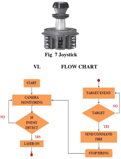
Fig 7 Joystick
VI. FLOW CHART
VII. RESULT
Fig 8: Simulated results of RF module.
This is the simulated result for the radio frequency module, which shows the wireless transmission of the data. It uses encoder and decoder which is used to convert the parallel data to serial and serial to parallel data respectively.
Fig 9: Remote unit at the receiver section.
The given image shows the assembly which is to be placed at the receiver side that is the assembly of the gun along with the laser, the camera and the vehicle used for the movement of the gun and the camera.
VIII. SUMMARY
REFERENCES
[I] Tejashree M. Hedaoo, Dr.N.G.Bawne, “A
wireless portable self defensive manchine gun”Dept. Of Computer Science & Engineering G.H Raisoni College Of Engineering, Nagpur
[II] KARTHIKEYAN.A & SARATH KUMAR.V.
“Border security system”International Journal of Engineering Research& Technology (IJERT) ISSN: 2278-0181 Vol. 1 Issue 5, July-2012.
[III] Morrie son G.D. “A camera based input device
for large interactive displays” Computer Graphics and Applications, IEEE July-Aug. 2005
[IV] “Antenna and wave propagation”,
Sathyaprakashan, K. D. Prasad, 1996.
[V]“Communication system and networks”, Lewis McKenzie, McGraw hill publication,1998
[VI Hemangi N. Patil and Sharada N. Ohotkar“Design and simulation of software defined radio using MATLAB Simulink”, IEEE
11th International conference on wireless and optical communication networks 2014,Vijaywada, 11th to 13th 2014, ISBN no. 978-1-4799-3155-2]