Design and Implementation of a GSM Based
Remote Home Security System Using Arduino
UNO Micro-Controller (ATMEGA 328)
E. Elbakush1, K. Aziz2
College of Engineering and Computing, Al Ghurair University, Dubai Academic City, Dubai, UAE1,2
ABSTRACT:This paper discusses the design and implementation process of a security system that is microcontroller
based and that is applicable at residential homes or small commercial buildings such as offices. The system is GSM based a wireless technology that consumes very small amount of power. A microcontroller has been used to save the instructions (the program code) that will be sent to the home owner in case there is a breach of security at the premises where the system is installed. Other peripherals working in conjunction with the microcontroller are LEDs, power supply unit, a PIR motion detection sensor and a Global System for Mobile Communication (GSM) Module. The microcontroller is placed on an Arduino board from which the other peripherals are connected. The PIR sensor detects motion and its output becomes high, detectable by the microcontroller which in turn sends a signal to the GSM module. The module then places a call to the premise owner to alert about a possible intrusion. This report details the design procedure and implementation of the system by analyzing similar systems under literature review. The system is first simulated through Proteus software and the results discussed. The design and implementation of the hardware and software have then been discussed.
KEYWORDS:Security Systems; Arduino UNO; GSM Module; Wireless Technology.
I.INTRODUCTION
Given that security has become a worldwide concern, the number of security firms has been on the increase. These firms have come up with innovative ways of securing homes and offices. The system designed here is an innovative way of detecting an intrusion and alerting the concerned parties, that is, the owner and/or the security firm, about the intrusion. The system is microcontroller based and is a wireless, GSM based communication approach with very low power consumption. The system secures the entry points into the house or office through magnetic relays connected to sensors that are used to relay signals through a public telecom network [1]. The system does not deter the intruder but alerts the concerned persons about the intrusion and the persons will take action based on the information sent to them [2].
The paper is divided into two main parts integrated to function as one. The first part detects when there is motion detected at the point of entrance into the premise where the system has been installed. The second part revolves around the GSM Module. This part is used to relay information to a handheld communication device, that is, a mobile phone or a tablet, to the home owner or the security firm. The receiver of the message is then supposed to initiate the next course of action, such as, deploy security personnel to the location [3], [4].
phased out with smart systems. These systems are able to detect unauthorized entry and alert the property owner in real time. This is a much bigger and preferred improvement over the traditional big padlocks that cannot deter intruders. Thus, this paper seeks to contribute to this growing sector of automated home security systems.
The main aim of this paper is to come up with a home security system that can alert the home owner in real time in case there is an intrusion at the house. For this main objective to be achieved, three specific objectives were developed and cumulatively contribute to the overall achievement of the main objective. These specific objectives include;
1. To analyze and evaluate existing home security systems in terms of their cost and efficiency and come up with an accurate, low cost alternative
2. To evaluate how a mobile based system, GSM, can be integrated into a security system to create a real-time awareness to a home owner
3. To design , to build and to test a prototype of the solution proposed in the first subjective.
While similar systems may exist in the market at the moment, they are quite costly and are not simplified to be very user friendly. This research aims to redesign such a system usinglocally available materials and simplified programming that makes it low cost and user friendly. The merits can be summed up as follows;
• Easy to Use The use of LED to display the status of the door (either locked or unlocked) is a very simple and low cost means of checking the door status. The use of GSM, and thank to technological advancement, is a simple yet reliable means of relaying information and covered all part of the globe thus the home owner is not limited to access alerts by his location away from the house.
• Portable The design developed is a small size and light weight prototype. This makes it easy to carry about and install anywhere the home owner may feel is necessary to secure.
• Low Cost / Affordable The prototype is made up of simple electronic components that are readily available and the microcontroller used is low cost. The impact is that the overall project cost is reduced and made fairly low thus the prototype becomes affordable to many households.
II.LITERATURE REVIEW
Automation of security systems can be traced way back with the development of electronic circuits in the early 20th century. Some of the systems were restricted to the military and were not accessible by the public. But with the advancement in technology, access to electronic components used to design the systems were made easily accessible and private security firms, mostly started by those who served in the military, started cropping up and selling these solutions mostly to the rich in the society. This section will review the development of automated security systems and how, of late, they have now been integrated with mobile communication gadgets [3]. Home automation can be taken to be the use of computers to control some functions at home, and this could be done either within the proximity of the home or remotely when one is far away from home [5]. Some of these functions include switching ON and OFF of the lights, operating a water sprinkler for lawn, heating and cooling the house, closing and opening the window curtains among many others. Such a home where these activities are automated is called a smart home [6]. A home automation system basically consist of a computer which is the central command station and other peripherals such as stepper motors and relay switches connected either by wires or wirelessly through a high speed internet connection [7], [8]. Such systems usually have a power backup of their own to ensure continuity when there is a power interruption.
A. History of Home Automation and Home Security Systems
complex security systems whichwere encrypted with passwords that made them more reliable. However, the cost of developing these systems and maintaining them was relatively high and thus the systems were limited to the wealthy in the society. However, with advancement in development of integrated circuits (ICs), their mass production has really reduced the cost per unit and they have been made readily available to the population masses [10], [11].
B.GSM Based Technology
GSM, a French word for Groupe Spciale Mobile is a standard Global system for mobile communication. GSM was developed by the European Telecommunications Standards Institute (ETSI) to describe protocols for second-generation (2G) digital cellular networks used by mobile phones [6]. GSM was first deployed in July 1991 in Finland and since then, it has been improved in stages (or generations) and currently, the fifth generation (5G) is being introduced in some parts of the world [12].
1) Advantages of GSM: There are several benefits that come with the GSM mode of telecommunication as given by [13] These include;
It has an improved spectrum efficiency.
International roaming; It is global and this means one can roam with one phone to any part of the world.
It is low cost in terms of the mobile sets used and setting up the base stations (BSs).
It allows for several services to be integrated other than just speech, for example text messaging and internet services (data services).
2) GSM and Home Security: There are several systems that have been developed that are capable of communicating
re- motely through mobile phones when certain pre-set parameters are violated. This kind of technology finds application in many fields, and one of them is home security [14]. A system can be set up to notify a home owner when there is a breach into their home. This project is based on such a system. The level of complexity ranges depending on the level of security needed. In this case, the project aims to come up with a very simple, low cost and efficient option that is easy to use and can be applied to any home [15].
III.SYSTEM COMPONENTS
The aims of the paper to create a low cost yet effective GSM based intruder alert for homes. It is composed of 3 basic modules, namely;
1) The micro controller 2) The GSM module 3) The PIR sensor
A. System Block Diagram
want it or not, that is, the buzzer can be a deterrent to the intruder as the noise can alert the persons in the house or it can be done away with such that the intruder will not know their activity is being detected.
Fig. 1 System Block Diagram
B. System Components
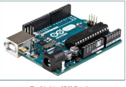
1) Arduino UNO Board: Arduino is an open-source platform for prototyping used by students for fairly low level programming because of its ease to use and simplicity. The Arduino Uno board is programmed through the Arduino IDE. This offers a flexible means of writing and uploading codes to the board through a PC. A microcontroller, ATMEGA 328, is mounted on the board and it is where the codes are uploaded. The controller is the logic unit of the system. It monitors the PIR input and instructs the GSM module to place the call to the predefined mobile number.
Fig. 2Arduino UNO Board
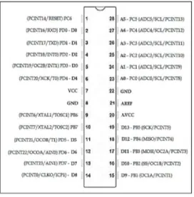
2) Arduino Uno Microcontroller (ATMEGA 328): This is a 28-pin microcontroller as depicted in figure 3 below. The
pin configuration of the microcontroller is explained below;
Input and Output There are fourteen digital pins and five analog pins. The digital pins are labelled D0 to D13 while the analog pins are labeled A0 to A4. These pins can be configured to act as either inputs or outputs depending on the programmer’s design. These pins operate on a 5V dc and maximum current of 40 mA with their resistance values ranging from 20 KΩ to 50 KΩ. The analog pins have 10 bits (210) resolution, meaning
Transmitter and Receiver Pin 0 (RX) is the receiver pin while Pin 1 (TX) is the transmitter pin. These two are used to carry TTL serial data.
Interrupt and Trigger Pins 2 and 3 are the interrupt pins. They are used to trigger an interrupt when they are on a low value .
Pulse Width Modulation, PWM There are six PWM pins, which include pins number 3, 5, 6, 9, 10, and 11. These pins provide an 8-bit PWM output.
RESET The reset button is used to bring down the entire board (the pins of the microcontroller) to a LOW.
3) The PIR Sensor: PIR is an acronym for passive infrared.
The sensor is used to detect any motion in front of it. The working principle is based on the fact that all living beings with a positive body temperature emit radiations. These are the radiations that the PIR sensor picks up. The sensor has a digital output which is HIGH in the presence of an intruder. This digital output is connected to one of the digital inputs of the micro controller.
Fig. 4. The PIR Motion Detection Sensor
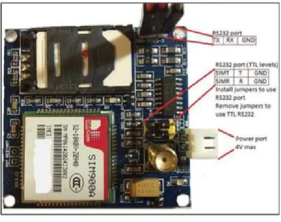
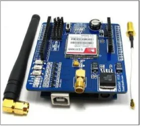
4) The GSM Module - SIM 900A: This paper uses the SIM 900A as the GSM Module. The Sim900A is a second generation (2G), two-band device operating on a frequency range of 900 to 1800MHz. this module has 2 built in RS232 serial ports. One port is used for common communications mostly between a PC and the module itself. The other port is also an RS232 serial port and is considered as a ”service port”, meaning that it is primarily used to debug the module and to upgrade the firmware. The purpose of this module is to achieve communication with the preset handset. The user defines a mobile number to which intrusion messages are sent to. AT commands are applied here to achieve this link once the controller instructs the GSM module to do so.
Fig. 5. GSM Module
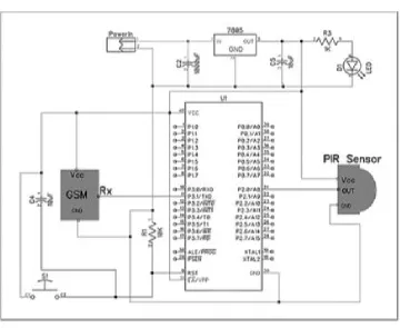
C. Circuit Diagram
rather than 6V. The LM7805 is a voltage regulator IOC which ensures the voltage at its output terminal is always 5V despite the variation on the battery. Capacitors C2 and C5 are used to smoothen the output and ensure steady DC. R3 is a limiting resistor for the LED (D1). The GSM module takes power directly from the output of the voltage regulator (VCC and GND) and so does the microcontroller. The operation of the module is controlled by the RX pin (receiver pin) which is powered by the microcontroller. The PIR sensor is equally powered by the voltage regulator but controlled through the receiver pin (OUT) connected to the microcontroller. Switch S1 is used to reset the microcontroller. Capacitor C4 ensures that there is steady voltage for the GSM module while resistor R1 is a limiting resistor for the microcontroller
Fig. 6. GSM Module
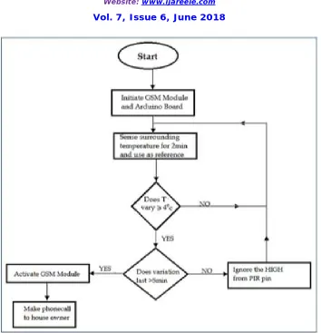
D. System Flow Chart
Fig. 7. The Circuit Diagram of the System
IV. DESIGN IMPLEMENTATION, TESTING AND RESULTS
This part of the paper discusses the components making up the different sections of the prototype as illustrated in the system block diagram. These are the electronic components that make up the hardware of the prototype.
A. Operation
Fig. 8. System Flow Chart
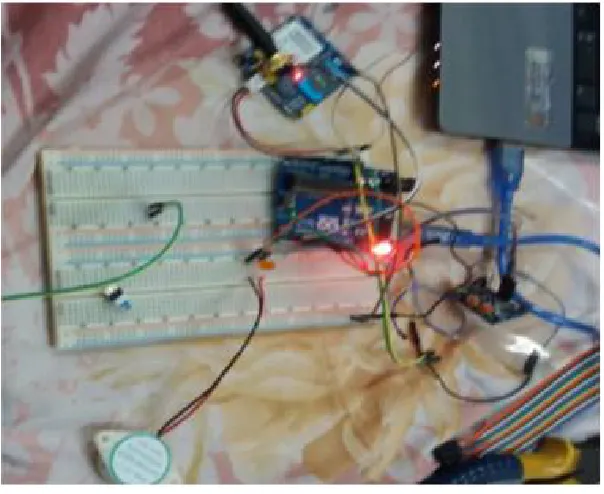
B. Implementation
The connection of the components, that is, wiring, is as shown in Figure (9) below while Figure (10) shown the proto- type which has been implemented in this paper.
Fig. 10. Final Prototype Circuit Implemented
C. Testing Results
There were three points of tests for this project, and these were;
1) The practicality of the temperatures set for actuation of the output pins. 2) The practicality of the times that are set in the program for heat detection
3) The overall performance of the prototype - that is, if it could make the call to the set number
It was observed that the response time increased with increase in temperature of the atmosphere. The possible explanation for this is that when the atmospheric temperature is low, then the PIR sensor is able to detect easily the body temperature and will send the signal for the call faster. When the atmospheric temperature is high, the PIR sensor will have difficulty detecting the temperature difference between the body and the surrounding. Also, the wind factor can be considered as a contributing factor. At high speeds, the wind cools off the body surface thus the PIR sensor cannot easily detect a body radiating heat.
From the test results, it is clear that the prototype is not a one- off solution as it is. Its performance is affected by some external factors, such as atmospheric temperature and wind. It would be recommended that the prototype, and more so PIR sensor itself, be installed in an enclosed area with no wind blowing. Also, if the system is being used to secure a door, the sensor should be placed as close as possible to where the intruder is likely to spend more time so that the sensor can get a constant reading to trigger the GSM module. The time recorded at 1pm (12 minutes) may be more than enough for some intruder to break in before the sensor can pick the motion.
VI.CONCLUSION
This paper has described how a microcontroller and a PIR sensor can be used with a GSM module to alert a home owner of an intrusion into their property. The materials used and the design itself are fairly simple and this has made the project easy to implement and low cost to obtain. The objectives set out in this paper have been achieved and the it can be termed as a success. The design, as it is, does not secure the premise of the owner. It only serves to alert the owner. The system can be improved further by introducing a buzzer or siren to also alert the neighbors. Also, a relay can be used to trigger a magnetic lock mechanism that can be used to reinforce the door lock if an intrusion is detected. That is, a part from just sending the signal and calling the owner, a siren can alert the neighbors if the owner is not near the house at the time and a magnetic lock can be triggered to reinforce the door lock. The recommendations on possible ways the system performance can be improved to make it more robust and practical.
REFERENCES
[1] H. Elkamchouchi and A.ElShafee,“Design and prototype implementation of SMS based home automation system,” in Electronics Design, Systems and Applications (ICEDSA), 2012 IEEE International Conference on, pp. 162–167, IEEE, 2012.
[2] S.KumarandS.I.Azid,“Performanceofalowcostbasedhomesecurity system,” International Journal of Smart Home, The University of South Pacific, Fiji, 2011.
[3] Y. Zhao and Z. Ye, “A low cost GSM/GPRS based wireless home security system,” IEEE Transactions on Consumer Electronics, vol. 54, no. 2, 2008.
[4] R. Hasan, M. M. Khan, A. Ashek, and I. J. Rumpa, “Microcontroller based home security system with GSM technology,” Open Journal of Safety Science and Technology, vol. 5, no. 02, p. 55, 2015.
[5] R. Anandan, “Wireless home and industrial automation security system using GSM,” Journal of Global Research in Computer Science, vol. 4, no. 4, pp. 126–132, 2013.
[6] N. Agarwal and S. G. Nayak, “Microcontroller based home security system with remote monitoring,” Special Issue of International Journal of Computer Applications, pp. 38–41, 2012.
[7] M.A.HossainandM.N. Hasan “Modernhomeautomationsystembased on AVR microcontroller,” International Journal of Scientific & Engineering Research, vol. 5, no. 1, pp. 1864–1868, 2014.
[8] G. S. M. Rana, A. A. M. Khan, M. N. Hoque, and A. F. Mitul, “Design and implementation of a GSM based remote home security and appliance control system,” in Advances in Electrical Engineering (ICAEE), 2013 International Conference on, pp. 291–295, IEEE, 2013.
[9] M. Van Der Werff, X. Gui, and W. Xu, A mobile-based home automation system. IET, 2005.
[10] I. S. Krishna and J. Ravindra, “Design and implementation of home security system based on WSNS and GSM technology,” International Journal of Engineering Science and Technology, vol. 2, pp. 139–142.
[11] H.Huang,S.Xiao,X.Meng,andY.Xiong,“Aremotehomesecurity system based on wireless sensor network and GSM technology,” in Networks Security Wireless Communications and Trusted Computing (NSWCTC), 2010 Second International Conference on, vol. 1, pp. 535–538, IEEE, 2010.
[12] A.KhanandR. Mishra “GPS–GSMbasedtracking system”International Journal of Engineering Trends and Technology, vol. 3, no. 2, pp. 161–164, 2012.
[13] J. Bangali and A. Shaligram, “Design and implementation of security systems for smart home based on GSM technology,” International Journal of Smart Home, vol. 7, no. 6, pp. 201–208, 2013.
[14] A. W. Ahmad, N. Jan, S. Iqbal, and C. Lee, “Implementation of zigbeegsm based home security monitoring and remote control system,” in Circuits and Systems (MWSCAS), 2011 IEEE 54th International Midwest Symposium on, pp. 1–4, IEEE, 2011.