Design of Compact Microstrip Patch Antenna
for Multiband Operations
Pradeep A S1, Laxman Kurnal2, Arpitha G P3, Mahamed Ashik M4
Assistant Professor, Dept. of ECE, Government Engineering College, Huvina Hadagali, Karnataka, India1
UG Student, Dept. of ECE, Mar Baselios Institute of Technology and Science, Nellimattom, Kerala, India2
UG Student, Dept. of ECE, Mar Baselios Institute of Technology and Science, Nellimattom, Kerala, India3
UG Student, Dept. of ECE, Mar Baselios Institute of Technology and Science, Nellimattom, Kerala, India4
ABSTRACT: This paper a probe fed microstrip patch antenna etched on FR4 epoxy substrate with thickness 1.6mm and dielectric constant 4.4 is designed using HFSS tool for multiband operation over the frequency range 2 to 5GHz wireless applications. The shape of the patch is modified to obtain the multiband operation. Parametric analysis is presented to observe the effects on antenna resonant frequency.
KEYWORDS: Frequency reconfigurable microstrip; S-slot antenna
I. INTRODUCTION
As wireless communication systems develop rapidly, reconfigurable antennas have received much attention. This is because they can after a diversity of performance related to operating frequency, polarization and radiation pattern to improve the communication quality and capacity. Nowadays, multifunctional applications are becoming increasingly popular, and such applications are integrating more and more services [1].One possible solution to this demand is to use reconfigurable antenna that tune to different frequency bands. Such an antenna would not cover all bands simultaneously, but provides narrow instantaneous bandwidths that are dynamically selectable at higher efficiency than conventional antennas [2].
Reconfigurability, when used in the context of antennas, is the capacity to change an individual radiator’s fundamental operating characteristics through electrical, mechanical, or other means. Thus, under this definition, the traditional phasing of signals between elements in an array to achieve beam forming and beam steering does not make the antenna “reconfigurable” because the antenna’s basic operating characteristics remain unchanged in this case. Ideally, reconfigurable antennas should be able to alter their operating frequencies, impedance bandwidths, polarizations, and radiation patterns independently to accommodate changing operating requirements. However, the development of these antennas poses significant challenges to both antenna and system designers. These challenges lie not only in obtaining the desired levels of antenna functionality but also in integrating this functionality into complete systems to
II. ANTENNA DESIGN AND SIMULATION RESULTS
A. Conventional Patch Antenna Design
The length and width of the conventional patch antenna can be calculated from the equations (1)-(4) [1]
Where W is the width of the patch, L is the length of the patch, is the effective dielectric constant of the material, c is the speed of light in a vaccum, is the target frequency, is the dielectric constant of the substrate, h is the thickness of the substrate and ΔL
represents the extension in length called by fringing effect and by considering the dimension of the patch it can be conformably be ignored.
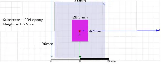
The geometry of the conventional microstrip patch antenna etched on FR4 epoxy substrate with thickness 1.6mm and dielectric constant of 4.4 shown in figure1 (a). The patch dimension is 28.3mm x 36.9mm. The substrate dimension is 86mm x 96mm.
Fig. 1(a) Conventional Microstrip Patch Antenna designed using HFSS for 2.4GHz application
From Fig. 1(b) We see that the dip is obtained at 2.4GHz which indicates the resonant frequency of the conventional patch antenna. The return loss at this frequency is -19dB. Lower value of return loss indicates maximum input energy is absorbed by the antenna (minimum reflection).
Fig. 1(c) 3D gain plot of MPA simulated using HFSS
From Fig. 1(c) we see that the gain for MPA simulated using HFSS is 3.0dB. This meets the industry standard requirement for Microstrip Patch antenna.
B. Proposed Microstrip Patch antenna with modified Patch
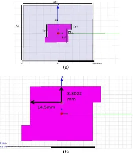
The 3D model of the proposed MPA with modified patch is as shown in Fig. 2
(a)
(b)
Two slots on the edges are introduced on the patch to obtain multiband operation. The width of both the slots are 2mm and the depth of the slots are varied to observe its dependence on resonant frequency.
Fig. 2 (c) Simulated return loss plot of modified MPA
As seen in Fig. 2(c) two resonant frequency bands are obtained at 2.45GHz and 4.6GHz with return loss equal to -15dB and -18dB respectively. Any frequency band with return loss less than -10dB is considered as resonant band.
Fig. 2(d) 3D gain plot of MPA with slots
As seen in Fig. 3(d), the gain of the modified MPA is 4.6dB. There is a 1dB increment in the gain compared to conventional patch antenna.
C. Parametric Analysis of modified structure MPA
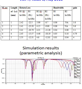
Later, the length of the slots towards the patch was varied to observe its dependance on the frequency. The results are tabulated as shown in table 1 and the corresponding graph is plotted in Fig. 2(e)
1.00 1.50 2.00 2.50 3.00 3.50 4.00 4.50 5.00 Freq [GHz] -20.00 -17.50 -15.00 -12.50 -10.00 -7.50 -5.00 -2.50 0.00 d B (S (2 ,2 )) HFSSDesign1
XY Plot 17 ANSOFT
m1
m2 Curve Info
dB(S(2,2)) Setup1 : Sweep Name X Y
Fig. 2(e) Parametric analysis of modified MPA
It can be seen from Fig. 2(e) that as we vary the length Lx1 from 1mm to 6mm, the resonant frequency in 4Ghz shifts towards 5GHz. This technique can be adopted by antenna designers to design an antenna for 2 to 5GHz applications.
III.CONCLUSIONS
In this paper, a modified MPA etched on FR4 epoxy substrate with thickness 1.6mm and dielectric constant 4.4 was designed for 2 to 5 GHz multiband operation. To obtain the multiband operation two slots were introduced to modify the shape of the patch. Parametric analysis of the depth of the slots was performed and observed to change the resonant frequency in the second band. The modified structure showed a 1dB improvement in gain over the conventional MPA.
In future, the designed antennas can be fabricated and tested in real time environment to validate the results.
REFERENCES
[1] S.-J.Shi and W.-P.Ding, “Radiation Pattern Reconfigurable Micro strip antenna for WiMAX Application”, Electronics Letters, 30th April 2015 vol.51 No.9 pp. 662-664.
[2] Junying Liu, Jinping Zhang, Weidong Wang, Dongjin Wang, “Compact Reconfigurable Micro strip Antenna for Multi-band Wireless Application”, IEEE 2007 International Syposium on Microwave, Antenna, Propogation, and EMC Technologies for wireless communication.
[3] Sriram Kumara, Harshitha Golib, Priya Baskarand, P.P.Angelae “Novel Reconfigurable Micro strip Antenna”, 2008 IEEE Region 10 Colloquium and the Third International Conference on Industrial and Information Systems, Kharagpur, INDIA December 8 -10, 2008.
[4] D.-H.Hyun, J.-W.Baik, S.H.Lee & Y.-S.Kim, “Reconfigurable Micro strip Antenna with Polarization Diversity”, ELECTRONICS LETTERS (10th April 2008). [5] Manoj S Parihar, Student Member, IEEE 1, A.Basu, Member IEEE 2, and S. K. Koul, Senior Member, “Polarization reconfigurable Micro strip antenna”, IEEE 3
Centre for Applied Research in Electronics, Indian Institute of Technology Delhi, New Delhi-110016, INDIA (2009). [6] Jung. Kim and C. G. Christodoulou, “Simple reconfigurable micro strip antenna for wideband applications”, 2010 IEEE.
![Fig. 2 (c) Simulated return loss plot of modified MPA Freq [GHz]](https://thumb-us.123doks.com/thumbv2/123dok_us/7764050.1275722/4.595.197.403.217.363/fig-simulated-return-loss-plot-modified-mpa-freq.webp)