ISSN (Print) : 2320 – 3765
ISSN (Online): 2278 – 8875
I
nternational
J
ournal of
A
dvanced
R
esearch in
E
lectrical,
E
lectronics and
I
nstrumentation
E
ngineering
(A High Impact Factor, Monthly, Peer Reviewed Journal)
Website: www.ijareeie.com
Vol. 8, Issue 4, April 2019
Microfluidic Syringe Pump Using Arduino
Dr.Azha Periyasamy1, R. Jeya Kumar2, T. Karuppiah3
Assistant Professor, Dept. of E&I, Bharathiar University, Coimbatore, Tamil Nadu, India1 PG Student, Dept. of E&I, Bharathiar University, Coimbatore, Tamil Nadu, India2 Ph.D., Research Scholar, Dept. of E&I, Bharathiar University, Coimbatore, Tamil Nadu, India3
ABSTRACT: Syringe pumps are used to deliver precise amounts of fluid at specific time intervals. It delivers measured amounts of fluids or medications into the bloodstream. In this project syringe pump control with Arduino microcontroller. So we have flexible platform for one or more syringe pump control with same time. Easily operate, programmable and also add sensors reconfigurable device easily depend upon our needs. This project is to made “inexpensive and compact”.
KEYWORDS: Arduino Uno; syringe pump; stepper motor; LCD keypad shield;
I.INTRODUCTION
Microfluidics is widely used in research ranging from bioengineering and biomedical disciplines to chemistry and nanotechnology. Infusion pumps delivering fluids in large or small amounts, and may be used to deliver nutrients or medications , such as insulin or other hormones, antibiotics, chemotherapy drugs, and pain relievers etc.
Commercially available syringe pumps are probably high cost and have inherent limitations due to their flow profiles. so we develop low cost, flexible platform for add some future depend on our needs and no limitations.
Here, we present a low-cost syringe pump that uses to regulate the pressure into microfluidic chips. Using an open-source microcontroller board (Arduino), we demonstrate an easily operated and reconfigurable program syringe pump, stepper motor control of the pressure at the inlets of microfluidic geometries.
II.EXPERIMENTALDESCRIPTION
AN OBJECTIVE OF THE PROJECT: The main work of this project is control using stepper motor to push the slider precisely. The infusion pump is depend on the movement of the slider (Fig 1). So we can give accurate low or high flow rate of liquid to the infusion pump. The flow rate speed is depending on the requirements of our needs. The timing of liquid flow rate is given by the control setup and it can be seen by LCD screen.
Fig. 1 Mechanical setup
(Red mark slider only movable)
III.HARDWAREDESCRIPTION
Fig. 2 Block Diagram of Syringe Pump
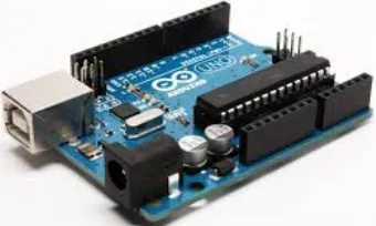
ARDUINO UNO: The Arduino UNO is a smaller scale microcontroller board dependent on the Atmega328. It has 14 computerized information/yield pins (which 6 can be utilized as PWM outputs), ICSP header, and a reset button. It contains everything expected to help the miniaturized scale controller, simply associated it to a PC with a USB link or power it with a connector or battery to begin. Thud the program code is written and uploaded in Arduino board.
ISSN (Print) : 2320 – 3765
ISSN (Online): 2278 – 8875
I
nternational
J
ournal of
A
dvanced
R
esearch in
E
lectrical,
E
lectronics and
I
nstrumentation
E
ngineering
(A High Impact Factor, Monthly, Peer Reviewed Journal)
Website: www.ijareeie.com
Vol. 8, Issue 4, April 2019
Input voltage – 5v to 12v.Most micro controller systems are limited to windows.simple clear programming environment-the Arduino software easy to use.yet flexible enough for advanced to make this blind navigation project. 16 MHz crystal oscillator and USB connection, it is suitable to be used as a microcontroller. Based on ATmega328, this microcontroller board can simply connect to computer using USB cable or using adapter to connect with battery to get started. In this project, Arduino UNO was powered with 9V battery which is in the range of recommended voltage.
STEPPER MOTOR: A stepper motor is an electromechanical device which converts electrical pulses into discrete mechanical movements. The shaft or spindle of a stepper motor rotates in discrete step increments when electrical command pulses are applied to it in the proper sequence. The motors rotation has several direct relationships to these applied input pulses. The sequence of the applied pulses is directly related to the direction of motor shafts rotation. The speed of the motor shafts rotation is directly related to the frequency of the input pulses and the length of rotation is directly related to the number of input pulses applied.
Fig. 4 Stepper motor
Angular accuracy in micro stepper motors is around ±1.8° or 200 steps per revolution, however, when higher resolution is necessary micro-stepping arise as an excellent solution. Micro-stepping is a way of controlling the current to the stepper motor windings (or stator) through pulse-width modulated voltage, which means that the current flowing to the windings have a sin waveform. This control method allows dividing every 1.8 degrees step up to 64 times, generating 0.028° angle step or 12,800 micro-steps per revolution, which provides smoother and precise operation.
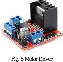
L298N MOTOR DRIVER: Motor drivers acts as an interface between the motors and the control circuits. Motor require high amount of current whereas the controller circuit works on low current signals.
So the function of motor drivers is to take a low-current control signal and then turn it into a higher-current signal that can drive a motor.
Fig. 5 Motor Driver
Fig. 6 LCD Display
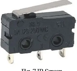
LIMIT SWITCHES: It automatically monitor and indicate whether the movement limits of a particular device have been exceeded. A standard industrial limit switch is an electromechanical device that contains an actuator linked to a series of contacts. When an object meets the actuator, the limit switch triggers the contacts to either form or break an electrical connection. Limit switches are commonly employed in a wide range of applications and under a variety of operating conditions due to their ease of installation, relatively straightforward design, ruggedness, and reliability.
Fig. 7 IR Sensor
SYRINGE PUMP: Syringe pump is designed to deliver drug at a predetermined rate and speed. In recent years, pharmaceutical companies have developed more and more concentrated and effective medicine. Hence, these medicines are required to be injected very slowly as well as continuously. Syringe pumps are particularly helpful under such circumstances as they are programmed to do deliver drug through the vein at a determined rate. Syringe pump generally consist of a drum that is attached to a piston. The piston is operated by a motor through a drive screw or worm gear which helps in pushing the plunger of syringe in or out resulting in a smooth flow. The syringe is engaged on a clamp on the frame and the plunger of the syringe is displaced by movement of drum. Most of the syringe pump can work with different syringes of different diameters, but the diameter has to be entered in beginning to make sure correct volume is dispensed.
ISSN (Print) : 2320 – 3765
ISSN (Online): 2278 – 8875
I
nternational
J
ournal of
A
dvanced
R
esearch in
E
lectrical,
E
lectronics and
I
nstrumentation
E
ngineering
(A High Impact Factor, Monthly, Peer Reviewed Journal)
Website: www.ijareeie.com
Vol. 8, Issue 4, April 2019
IV.SOFTWAREDESCRIPTION
ARDUINO IDE: The program developed in Arduino IDE V.1.8.5 software by using set of C/C++ languages. Arduino is an open source tool software for the development of embedded application and it is an integrated development toolset for programming the Arduino.
V.RESULTANDDISCUSSION
TABLE – 1 Standard Flow rate syringe pump details
This flow rate values are depend on syringe pump manufacturing company. All size of syringe pump has different diameters. So it has different flow rate.
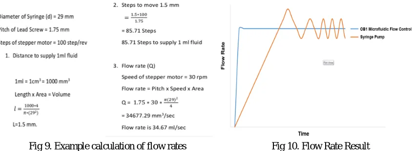
A syringe pump, like other injection systems, can be mainly characterized by its settling time and its stability. The settling time of a syringe pump depends not only on the quality of its mechanics, but also, and more importantly, on the fluidic resistance and the fluidic compliance of the experimental setup. The elasticity and high fluidic resistance of syringes, tubing and chips are important parameters to obtain a stable flow rate in most microfluidic systems.
Fig 9. Example calculation of flow rates Fig 10. Flow Rate Result
V. CONCLUSION
This paper demonstrates programmable syringe pump and control by stepper motor. Stepper motor shaft rotate step by step. It control by continuous pulse from microcontroller.It regulate pressure to controlled flow. So we can have customize platform. Easily change program and add sensor depend upon our needs and No limitations. It has low cost compared commercial syringe pump. In this application used to biomedical application such as infusion pump inject to human vein, it precisely delivered medicine and liquid food etc.
REFERENCES
[1] P. Barbosa,R.Ruge, J. Alves, I. Silva, M. A. Marques – Developing the control system of a syringe infusion pump (2014)
[2] V.E. Garcia, J. Liu, J.L. DeRisi - Low-Cost Touchscreen Driven Programmable Dual Syringe Pump for Life Science (2018)
[3] T.J. Hinton, A.W. Feinberg - Lorge volume of syringe pump extruder for desktop 3D printers (2018)
[4] V. Lien, F. Vollmer, Microfluidic flow rate detection based on Integrated optical fiber cantilever, Lab Chip (2007)
[5] Martin Oellers, Frank Bunge, Poornanchandra Papireddy Vinayaka,Sander van den Driesche, Michael J. Vellekoop– Optofluidic
flow-ratio sensor system for microchannels
[6] A.T Cohen - A computer-controlled syringe driver for us During anaesthesi
[7] Seok Hwan Lee, Woong Kang, Sejong Chun - Dynamic behaviour analysis of drug delivery devicesusing a dynamic gravimetric Method