Intelligent Control for Shunt Compensation
Sayali Ashok Kulkarni1, Ashwini Pawar2
Student, Department of Electrical Engineering, GHRIET Wagholi Pune, India.1 Guide, Department of Electrical Engineering, GHRIET Wagholi Pune, India2
ABSTRACT: The paper intends to develop the artificial neural network control algorithm for the control of DSTATCOM for the improvement of power quality. The presence of nonlinear loads makes the voltage to be deviated and current to be distorted from its sinusoidal waveform quality. Thus harmonics elimination, load balancing and voltage regulation is the heavy task that has to be accomplished to maintain the quality of the power. The performance of any device depends on the control algorithm used for the reference current estimation and gating pulse generation scheme. Thus the artificial neural network based Back Propagation (BP) algorithm has been proposed to generate the triggering pulses for the three phase H bridge inverter (DSTATCOM).The fundamental weighted value of active and reactive power components of load currents which are required for the estimation of reference source current is calculated by using BP-based control algorithm. Based on the difference of the target voltage and the generated voltage, the triggering pulse for the inverter is obtained by the BP algorithm. Then the voltage is injected at the point of common coupling to compensate the reactive power. Thus by regulating the voltage and compensation of reactive power, the power quality can be improved. The simulation modelling of the Back propagation algorithm controlled DSTATCOM and the PWM controlled DSTATCOM and the comparative analysis of the algorithms is presented in this paper.
KEYWORDS: DSTATCOM, Artificial Neural Network, Back propagation (BP) control algorithm, Reference current
Estimation, Power quality.
I. INTRODUCTION
shunt connected compensating device known as DSTATCOM for the extraction of active power and reactive power components of three-phase distorted load currents. Proposed control algorithm is used for PFC and ZVR modes of operation to maintain a balanced and sinusoidal supply current with a self-supporting dc bus of VSC of DSTATCOM, for this purpose Kohonen learning method has been used. Kohonen learning is used to extract the fundamental components of load current in terms of conductance and susceptance.
II.MOTIVATION
Power quality in distribution systems affects all the electrical and electronics equipment that are connected. This measures the deviation in the measurement of frequency, current and Voltage of the system. The use of power converters in power supplies, adjustable speed drives, is continuously increasing in recent years. This equipment draws harmonics currents from AC mains and increases the supply demands. The classification of loads includes linear (lagging power factor loads), nonlinear (current or voltage source type of harmonic generating loads), unbalanced and mixed types of loads. The power quality problems associated with these loads include, load unbalancing, harmonics, high reactive power burden, voltage variation. The power quality problems are compensated in a distribution system by the Custom Power devices. These custom power devices are classified as the DSTATCOM (Distribution Static Compensator), DVR (Dynamic Voltage Restorer) and UPQC (Unified Power Quality Conditioner). The power quality at the Point of common coupling is governed by standards such as IECSC77A, IEEE519-1992, IEEE-1531-2003 and IEC- 61000.
III.DSTATCOM MECHANISM
The D-STATCOM is a three phase shunt connected reactive power compensation equipment, whose output can be varied so as to maintain control of specific parameters of the electric power system by the generation and /or absorption of the reactive power. The DSTATCOM consists of three phase GTO/IGBT voltage source inverter (VSI), a coupling transformer with a leakage reactance and DC capacitor. The DSTATCOM topologies can be classified based on of switching devices, use of transformers for isolation, use of transformers for neutral current compensation. The ac voltage difference across the leakage reactance power exchange between the Power system and the DSTATCOM at the bus bar can be regulated to improve the voltage profile of the power system. This constitutes the primary duty of the DSTATCOM. However, a secondary damping function is added in to the DSTATCOM for enhancing power system oscillation stability. The D-STATCOM employs solid state power switching devices and provides rapid controllability of magnitude and the phase angle of the phase voltages. The DSTATCOM provides operating characteristics that of the rotating Synchronous compensator without the mechanical inertia.
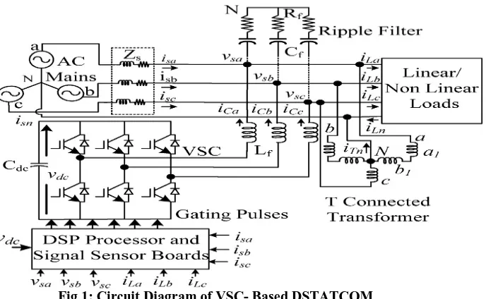
A three phase DSTATCOM based on Voltage Source Converter (VSC) is shown in Fig, where an ac mains with grid impedance is feeding three phase consumer loads.
Required components of DSTATCOM are VSC, interfacing inductors, series connected resistance and capacitance as a ripple filter for suppression of high frequency switching noise at Point of Common Coupling (PCC) voltage.
IV.LITERATURE SURVEY
1. Artificial Neural Network Controlled DSTATCOM for Power Quality Improvement
A three phase VSC based DSTATCOM has been implemented for compensation of nonlinear loads using BPT control algorithm to verify its effectiveness. The proposed algorithm has been used for extraction of reference source currents to generate the switching pulses for IGBTs of VSC of DSTATCOM. Various functions of DSTATCOM such as, load balancing and harmonic elimination have been demonstrated in PFC mode with DC voltage regulation of DSTATCOM. From simulation and implementation results, it is concluded that DSTATCOM and its control algorithm have been found suitable for compensation of nonlinear loads. These results show satisfactory performance of the BP control algorithm for harmonics elimination according to IEEE-519 guidelines in order of less than 5%. The DC bus voltage of the DSTATCOM has also been regulated to rated value without any overshoot or undershoots during load variation. Large training time in the application of complex system, selection of number of hidden layer in system is the disadvantage of this algorithm.
2. Control Algorithm for Conductance Estimation Using Neural Network Controller for a DSTATCOM
A control algorithm based on load conductance estimation using neural network for control of DSTATCOM has been implemented in a three phase four wire distribution system. The main factors for deciding the performance of DSTATCOM has been observed for detection of power quality problems in real-time and its accuracy. Test results have proved the effectiveness of proposed neural network algorithm for reactive power compensation, harmonics elimination, load balancing, neutral current compensation and increases efficiency under linear/nonlinear loads.
3. Power Quality Enhancement in Distribution System using ANN based DSTATCOM
VSC based DSTATCOM has been accepted as the most preferred solution for power quality improvement and to maintain rated PCC voltage. A three phase DSTATCOM has been implemented for compensation of nonlinear loads using BPT control algorithm to verify its effectiveness. The proposed BPT control algorithm has been used for extraction of reference source currents to generate the switching pulses for IGBTs of VSC of DSTATCOM. Various functions of DSTATCOM such as, harmonic elimination, load balancing and DC voltage regulation of DSTATCOM have been demonstrated. From simulation and implementation results, it is concluded that DSTATCOM and its control algorithm have been found suitable for compensation of nonlinear loads. The DC bus voltage of the DSTATCOM has also been regulated to rated value without any overshoot or undershoots during load variation. Large training time in the application of complex system, selection of number of hidden layer in system is the disadvantage of this algorithm.
4. Power Quality Improvement by Back Propagation Control Algorithm
load variation. Large training times in the application of complex system, selection of number of hidden layer in system are the disadvantage of this algorithm.
V.SCHEMATIC DIAGRAM OF DSTATCOM
The Distribution Static Compensator (DSTATCOM) is a voltage source inverter based static compensator that is used for the correction of line currents. Connection (shunt) to the distribution network is via a standard power distribution transformer. The DSTATCOM is capable of generating continuously variable inductive or capacitive shunt compensation at a level up its maximum MVA rating. The DSTATCOM continuously checks the line waveform with respect to a reference ac signal, and therefore, it can provide the correct amount of leading or lagging reactive current compensation to reduce the amount of voltage fluctuations.
1. Limiting voltage swells caused by capacitor switching. 2. Reduction of voltage sags due to common feeder faults.
3. Controlling the voltage fluctuations caused by customer load variations. It was found 2.5% to 0.2% with DSTATCOM. This reduces voltage flicker substantially.
4. Based on the control algorithm, the frequency of mechanical switching operations (involving load tap changing (LTC) transformers and mechanically switched capacitors) is reduced that is beneficial for maintenance. 5. Increase in the maximum load ability of the system (in particular, increase in the induction motor load that can
remain stable through a major disturbance, such as a loss of primary in feed). The controller of DSTATCOM suggested in has three levels given below:
6. Fast voltage regulator.
7. Fast current limiter and overload management control. 8. Slow reset control.
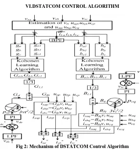
VI.DSTATCOM CONTROL ALGORITHM
Fig 2: Mechanism of DSTATCOM Control Algorithm
reference supply currents (Isa*, Isb*, Isc*) . In case of distorted voltages of AC mains, three phase PCC voltages are fed through band pass filters (BPFs) to filter noise and harmonics. To take care of unbalanced in PCC voltages, amplitude of each of these three phase voltages are estimated through squaring them and then fed through low pass filters (LPFs) as
Where Vsa = Vsa sin ωt , Vsb = Vsb sin(ωt − 2π⁄3) , and Vsc = Vsc sin(ωt − 4π⁄3)
Constant amplitudes of three phase PCC voltage are represented as, Vta,Vtb and Vtc . These are obtained after processing through low pass filters. In phase unit template with phase voltages (Vap, Vbp, Vcp) are estimated as
Amplitude of phase voltage (Vtp) at the PCC (Vsa, Vsb , and Vsc) is computed as
This amplitude Vtp may have ripples in it because of fundamental negative sequence voltage present in PCC voltages. This Vtp is processed through LPF to achieve amplitude of fundamental positive sequence PCC voltages and it is represented as Vt. Generally, power drawn (s) by nonlinear loads consists of total active power (Pt), reactive power (qt)
including harmonic components and others. Consider that phase “a” VA power drawn from ac mains is as
The instantaneous value of conductance (ga) of phase “a” is estimated in distorted load current as
Similarly, instantaneous value of phases “b” and “c” conductance’s (gb, gc) are estimated as
Where Vta, Vtb, Vtc and Pta, Ptb, Ptc are the amplitude of individual phase (a ,b and c ) voltages and active power of connected loads. The value of Pta, Ptb, Ptc are considered as multiplication of (VtVapiLa), (VtVbpiLb), and (VtVcpiLc),
respectively. The instantaneous approximate fundamental value of three load conductance’s (ga1, gb1, gc1) are calculated
using band pass filter (BPF) in load currents and respective constant PCC phase voltages. Its accuracy depends upon the cut off frequency of BPF. Updated value of fundamental active components of three phase load conductance (Ga1,
.
Where (ga-ga1), (gb-gb1), and (gc-gc1) are considered as conductance due to nonfundamental quantity. These are
presented as gah, gbh and gch, respectively. Performance of algorithm depends upon learning rate (Ʈ). Its best value is
found 0.11 for this application and varies between zero to one. After iterations, unique value of Ga1, Gb1 and Gc1are
obtained. Details of used Kohonen learning algorithm is given in Appendix B. Average conductance is responsible to maintain balanced supply currents even at unbalanced loads. It is also applicable in unbalanced PCC voltages. Average conductance due to active power of the three phase load is presented as GL1 and it is calculated as
Reference dc bus voltage Vdc* and sensed dc bus voltage of a VSC used as DSTATCOM are compared and error in dc
bus voltage at rthsampling instant is expressed as
The dc link voltage of VSC is regulated using a proportional-integral (PI) controller. The dc link voltage error (Vde) is
processed through a PI controller. The output of dc link voltage PI controller for maintaining dc link voltage of the DSTATCOM of the rth sampling instant is expressed as
Where Pcp(r) considered as the active power component drawn from ac mains and kdp and kdi are the proportional and
integral gain constants of the dc link PI voltage controller. It is denoted by Pcp for calculation purpose. Active power
losses of VSC is compensated using this component. The conductance (Gd) corresponding to output of dc link voltage
controller Pcp is calculated as
The total conductance corresponding to active power of the supply is calculated as
In-phase components of reference supply currents are estimated as
The instantaneous value of susceptance (ba) of phase “a” is estimated as
Similarly, instantaneous value of phase “b” and phase “c” susceptances (bb,bc) are estimated as
Where ba, bb,bc are the susceptances corresponding to reactive power (qta, qtb, qtc) for linear and nonlinear part of
connected loads. The value of qta, qtb, qtc are considered as multiplication of (VtVaqiLa), (VtVbqiLb) , and (VtVcqiLc) for
respective phases. Approximate instantaneous fundamental value of three load Susceptances (ba1, bb1, bc1,) is calculated
using band pass filter in load currents and respective constant PCC phase voltages. Updated value of fundamental reactive power components of three phase load susceptances (Ba1, Bb1, Bc1) atrth sampling instant are written as
Where (ba-ba1), (bc-bc1), and (bc-bc1) are considered as susceptances due to non-fundamental quantity. These are
represented as bah, bbh , and bch , respectively.
Average susceptance due to reactive power components of the loads is presented as BL1 and it is calculated as
The PCC voltage is regulated using a PI voltage controller. The terminal voltage error Vte is difference of the reference
and sensed amplitude of load terminal voltage at the rth sampling instant as
Where Vt*(r) is the amplitude of the reference PCC voltage and Vt(r) is the amplitude of the sensed and filtered
three-phase ac voltages at rth instant. The output of the PI voltage controller, Pcq(Ʈ) formaintaining the PCC voltage at a
Where ktp and kti are the proportional and integral gain constants of the PCC PI voltage controller, Vte(r) and Vte(r-1)
are the voltage errors in the rth and (r-1)th instants and pcq(r-1) is the required reactive power at the(r-1)th instant. Term
pcq(r) is represented as pcq. It is extra leading reactive power components which is required to compensate PCC voltage
drop. In this case, nature of supply current is leading with respect to PCC voltage and amplitude depends upon the required voltage compensation. The susceptance (Bq) corresponding to pcq is calculated as
The susceptance of reactive power components of supply is calculated as
The quadrature components of reference supply currents are estimated as
The total reference supply currents (isa*, isb*, and isc* ) are calculated as sum of in phase and quadrature component
reference supply currents of individual phases as given in form of equations
These reference supply currents (isa*, isb*, and isc* ) and sensed supply currents (isa, isb, and isc ) are compared and their
current errors are amplified through PI current controllers. The output of PI current controller is fed to the PWM current controller to generate the gating pulses of the IGBTs (Insulated Gate Bipolar Transistors) of the VSC. Control of DSTATCOM using above procedure is defined as indirect extraction of current error components between supply current and extracted reference supply current. Only in phase components of reference supply currents are used in PFC mode for generation of switching pulses.
VII. FLOW OF THE SYSTEM
Fig 3: Flow chart of Kohonen learning algorithm for training of phase “a” conductance
VIII. SIMULATION RESULT
A Distribution Static Synchronous Compensator (DSTATCOM) is used to regulate voltage on a 25-kV distribution network. Two feeders (21 km and 2 km) transmit power to loads connected at buses B2 and B3. A shunt capacitor is used for power factor correction at bus B2. The 600-V load connected to bus B3 through a 25kV/600V transformer represents a plant absorbing continuously changing currents, similar to an arc furnace, thus producing voltage flicker. The variable load current magnitude is modulated at a frequency of 5 Hz so that its apparent power varies approximately between 1 MVA and 5.2 MVA, while keeping a 0.9 lagging power factor. This load variation will allow you to observe the ability of the DSTATCOM to mitigate voltage flicker.
When the secondary voltage is higher than the bus voltage, the DSTATCOM acts like a capacitor generating reactive power.
and Vq voltages are converted into phase voltages Va, Vb, Vc which are used to synthesize the PWM voltages. The Iq reference comes from the outer voltage regulation loop (in automatic mode) or from a reference imposed by Qref (in manual mode). The Id reference comes from the DC-link voltage regulator.
IX. DSTATCOM DYNAMIC RESPONSE
During this test, the variable load will be kept constant and you will observe the dynamic response of a DSTATCOM to step changes in source voltage. Check that the modulation of the Variable Load is not in service (Modulation Timing [Ton Toff]= [0.15 1]*100 > Simulation Stop time). The Programmable Voltage Source block is used to modulate the
internal voltage of the 25-kV equivalent. The voltage is first programmed at 1.077 pu in order to keep the DSTATCOM initially floating (B3 voltage=1 pu and reference voltage Vref=1 pu). Three steps are programmed at 0.2 s, 0.3 s, and 0.4
s to successively increase the source voltage by 6%, decrease it by 6% and bring it back to its initial value (1.077 pu). Start the simulation. Observe on Scope1 the phase A voltage and current waveforms of the DSTATCOM as well as controller signals on Scope2. After a transient lasting approximately 0.15 sec., the steady state is reached. Initially, the source voltage is such that the DSTATCOM is inactive. It does not absorb nor provide reactive power to the network. At t = 0.2 s, the source voltage is increased by 6%. The DSTATCOM compensates for this voltage increase by absorbing reactive power from the network (on trace 2 of Scope2). At t = 0.3 s, the source voltage is decreased by 6% from the value corresponding to Q = 0. The DSTATCOM must generate reactive power to maintain a 1 pu voltage. Note that when the DSTATCOM changes from inductive to capacitive operation.
Active-Reactive Power and Inverter DC Voltage (Fig4) (Scope1)
DSTATCOM Output (Fig6) (Scope3)
X. MITIGATION OF VOLTAGE FLICKER
During this test, voltage of the Programmable Voltage Source will be kept constant and you will enable modulation of the Variable Load so that you can observe how the DSTATCOM can mitigate voltage flicker. In the Programmable Voltage Source block menu, change the "Time Variation of" parameter to "None". In the Variable Load block menu, set the Modulation Timing parameter to [TonToff]= [0.15 1] (remove the 100 multiplication factor). Finally, in the
DSTATCOM Controller, change the "Mode of operation" parameter to "Q regulation" and make sure that the reactive power reference value Qref (2nd line of parameters) is set to zero. In this mode, the DSTATCOM is floating and
performs no voltage correction.
Run the simulation and observe on Scope3 variations of P and Q at bus B3 (1st trace) as well as voltages at buses B1 and B3 (trace 2). Without DSTATCOM, B3 voltage varies between 0.96 pu and 1.04 pu (+/- 4% variation). Now, in the DSTATCOM Controller, change the "Mode of operation" parameter back to "Voltage regulation" and restart simulation. Observe on Scope 3 that voltage fluctuation at bus B3 is now reduced to +/- 0.7 %. The DSTATCOM compensates voltage by injecting a reactive current modulated at 5 Hz (trace 3 of Scope3) and varying between 0.6 pu capacitive when voltage is low and 0.6 pu inductive when voltage is high.
All the systems with these controller configurations are verified by performing simulation in MATLAB and Simulink. Performance evaluation of all these controller configuration is carried out.
Three-phase source is connected to the three-phase series RL Load. The parameter of load are as follows.
1.Nominal phase to Phase voltage(Vrms)=Vabcl=138KV 2.Nominal Frequency Fn=(FF)=60HZ
3.Active Power(AP)=50*106Watt 4.Reactive Power(RP)=30*106Var
The parameter of source are as follows. 1.Phase to Phase rms voltage(Vabc)=138KV 2.Frequency(FF)=60HZ
Fault is given on load side at time (FLT)=[0.0167,0.0833]sec
STATCOM is connected at PCC through Transformer and Three Phase LC Filter. Value, L(LC-LF)=0.2MH
C(LC-LF)=0.2MF Control Blocks are as follows.
Reference signal for operation of STATCOM generated using control block. This block consists of
2.abc to dq transformation block Discrete PI controller block
The Proportional gain Kp and integral gain Ki is calculated using Neural Network. The values obtained for neural network are
Kp= 0.1 Ki= 2
The reference signal generated is given to PWM generation block. The output of PWM pulse of Frequency 2KHZ
The PWM pulse are given to the three-phase bridge inverter for STATCOM operation. The STATCOM operation is observed under
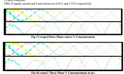
1.Normal condition 2.Faulty condition
THD of supply current and Load current are 0.01% and 2.53% respectively.
Fig (7) scope2Three Phase source V-I measurement
Fig (8) scope3 Three Phase V-I measurement at pcc
As current increases harmonics increases and after using Dstatcom operation harmonics disturbances reduces.
Fig (9)Scope 4 PWM Generator
Fig (11) scope 6 Three Phase Reference and Source Voltage
Uref generate minimum six pulses. carrier frequency is 2Khz
Fig (12) bode plot without NN
Fig (13)bode plot with NN
Fig(14) THD for Source
Fig (15) THD for Load
XI. FUTURE SCOPE
Possible extensions to our work include: 1. Realization of intelligent DSTATCOM
2. Study and control of power quality issues for deregulated power system.
XII. CONCLUSION
A DSTATCOM has been implemented in a three phase four wire distribution system. Three leg VSCwith a T connected non-isolated transformer has been used as DSTATCOM the main factors for deciding the performance ofDSTATCOM has been observed for detection of power qualityproblems in real-time and its accuracy. Test results have provedthe effectiveness for reactive power compensation, harmonics elimination, load balancingand neutral current compensation under linear/nonlinear loads.
REFERENCES
[1] H. Akagi, “Active harmonic filters,” Proc. IEEE, vol. 93, no. 12, pp. 2128–2141, Dec. 2005.
[2] A. Ghosh and G. Ledwich, Power Quality Enhancement Using Custom Power Devices. Delhi, India: Springer International, 2009.
[3] IEEE Recommended Practices and Requirement for Harmonic Control on Electric Power System, IEEE Std. 519, 1992.
[4] IEEE Guide for Application and Specification of Harmonic Filters, IEEE Std. 1531, 2003. [5] Limits for Harmonic Current Emissions,
International Electrotechnical Commission, IEC61000-3-2, 2000.
[6] A. Terciyanli, T. Avci, I. Yilmaz, C. Ermis, N. Kose, A. Acik,A. Kalaycioglu, Y. Akkaya, I. Cadirci, and M. Ermis, “A current source converte
based active power filter for mitigation of harmonics at the interface of distribution and transmission systems,” IEEE Trans. Ind. Appl., vol. 48, no. 4, pp. 1364–1386, Jul./Aug. 2012.
[7] G. G. Pozzebon, A. F. Q. Gonçalves, G. G. Pena, N. E. M. Moçambique, and R. Q. Machado, “Operation of a three-phase power converter
connected to a distribution system,” IEEE Trans. Ind. Electron., vol. 60, no. 5, pp. 1810–1818, Apr. 2013.
[8] Z. Yao and L. Xiao, “Control of single-phase grid-connected inverters with nonlinear loads,” IEEE Trans. Ind. Electron., vol. 60, no. 4, pp.
1384–1389, Apr. 2013.
[9] J. M. Espi, J. Castello, R. Garcia-Gil, G. Garcera, and E. Figueres, “An adaptive robust predictive current control for three-phase grid connected
inverters,” IEEE Trans. Ind. Electron., vol. 58, no. 8, pp. 3537–3546, August 2011.
[10] G. Benysek and M. Pasko, Power Theories for Improved Power Quality. London, U.K.: Springer-Verlag, 2012.
[11] P. Tenti, P. Mattavelli, and E. Tedeschi, “Compensation techniques based on reactive power conservation,” J. Elect. Power Quality Utilization,
vol. 8, no. 1, pp. 17–24, 2007.
[12] INSLEAY,A,ZARGARI,N.R,and JOOS,G,”A neural network controlled unity power factor three phase PWM rectifier”.Conference record of
IEEE-PESC,1994(1),pp.577-582.
[13] A. Bhattacharya and C. Chakraborty, “A shunt active power filter with enhanced performance using ANN-based predictive and adaptive
controllers,” IEEE Trans. Ind. Electron., vol. 58, no. 2, pp. 421–428, Feb. 2011.
[14] Y. Pan and J. Wang, “Model predictive control of unknown nonlinear dynamical systems based on recurrent neural networks,” IEEE Trans. Ind.
Electron., vol. 59, no. 8, pp. 3089–3101, Aug. 2012.
[15] J. V. Wijayakulasooriya, G. A. Putrus, and C. H. Ng, “Fast nonrecursive extraction of individual harmonics using artificial neural networks,”
IEE Proc. Gener. Transm. Distrib., vol. 152, no. 4, pp. 539–534, July 2005.
[16] L. Fausett, Fundamentals of Neural Networks: Architectures, Algorithms and Applications. Delhi, India: Person Education Asia, 2005.
[17] J. S. R. Jang, C. T. Sun, and E. Mizutani, Neuro Fuzzy and Soft Computing: A Computational Approach to Learning and Machine Intelligence.
Delhi, India: Person Education Asia, 2008.