International Journal of Research (IJR)
e-ISSN: 2348-6848, p- ISSN: 2348-795X Volume 2, Issue 10, October 2015Available at http://internationaljournalofresearch.org
An adaptive randomized DSTC scheme for two-hop cooperative
wireless networks
1
Dr.K.Sri Hari Rao
M.E, PHD, Professor and Head of the Dept of ECE, NRIIT, GUNTUR, Andhra
Pradesh,Email: [email protected]
2
katakamsetti Santhi
M.tech Student, Digital Electronics And Communication Systems, NRIIT, GUNTUR, Andhra
Pradesh, Email: [email protected]
ABSTRACT
An adaptive randomized distributed space-time
coding (DSTC) scheme is proposed for two-hop
cooperative MIMO networks. Linear minimum
mean square error (MMSE) receiver filters and
randomized matrices subject to a power
constraint are considered with an
amplify-and-forward (AF) cooperation strategy. In the
proposed DSTC scheme, a randomized matrix
obtained by a feedback channel is employed to
transform the space-time coded matrix at the
relay node. The effect of the limited feedback and
feedback errors are considered. Linear MMSE
expressions are devised to compute the
parameters of the adaptive randomized matrix
and the linear receive filters. A stochastic
gradient algorithm is also developed with
reduced
computational
complexity.
The
simulation results show that the proposed
algorithms obtain significant performance gains
as compared to existing DSTC schemes.
Keywords:-
MIMO; DSTC; AF and MMSE
INTRODUCTION
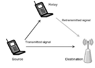
Relaying has become a widely accepted
means of cooperation in wireless networks. In
this paper, we focus on networks composed of
one source, one destination and one relay that
operates under the half-duplex constraint
i.e.,
the
relay can either receive or transmit, but not both
at the same time. The relay thus listens to the
source signal during a certain amount of time
(the first slot) and is allowed to transmit towards
the destination during the rest of the time (the
second slot).
International Journal of Research (IJR)
e-ISSN: 2348-6848, p- ISSN: 2348-795X Volume 2, Issue 10, October 2015Available at http://internationaljournalofresearch.org
signal from the source node and to forward it to
the destination station.
In cooperative wireless communication,
we are concerned with a wireless network, of the
cellular or ad hoc variety, where the wireless
agents, which we call users, may increase their
effective quality of service (measured at the
physical layer by bit error rates, block error rates,
or outage probability) via cooperation.
In a cooperative communication system,
each wireless user is assumed to transmit data as
well as act as a cooperative agent for another
user (Fig. 1). Cooperation leads to interesting
trade-offs in code rates and transmit power. In
the case of power, one may argue on one hand
that more power is needed because each user,
when in cooperative mode, is transmitting for
both users. On the other hand, the baseline
transmits power for both users will be reduced
because of diversity. In the face of this trade-off,
one hopes for a net reduction of transmit power,
given everything else being constant.
Fig 1
.
cooperative communication.
1.1
BENEFITS
OF
COOPERATIVE
TECHNOLOGY MIMO VIEW)
The benefits of MIMO technology that
help achieve such significant performance gains
are array gain, spatial diversity gain, spatial
multiplexing gain and interference reduction.
These gains are described in brief below.
Array gain
Array gain is the increase in receive SNR that
results from a coherent combining effect of the
wireless signals at a receiver. The coherent
combining may be realized through spatial
processing at the receive antenna array and/or
spatial pre-processing at the transmit antenna
array. Array gain improves resistance to noise,
thereby improving the coverage and the range of
a wireless network.
Spatial diversity gain
As mentioned earlier, the signal level at a
receiver in a wireless system fluctuates or fades.
Spatial diversity gain mitigates fading and is
realized by providing the receiver with multiple
(ideally independent) copies of the transmitted
signal in space, frequency or time. With an
increasing number of independent copies (the
number of copies is often referred to as the
diversity order), the probability that at least one
of the copies is not experiencing a deep fade
increases, thereby improving the quality and
reliability of reception. A MIMO channel with
M
Ttransmit antennas and M
Rreceive antennas
potentially offers M
TM
Rindependently fading
links, and hence a spatial diversity order of M
TM
RSpatial multiplexing gain
MIMO systems offer a linear increase in data
rate
through
spatial
multiplexing,
i.e.,
transmitting multiple, independent data streams
within the bandwidth of operation. Under
suitable channel conditions, such as rich
scattering in the environment, the receiver can
separate the data streams. Furthermore, each data
stream experiences at least the same channel
quality that would be experienced by a
single-input single-output system, effectively enhancing
the capacity by a multiplicative factor equal to
the number of streams. In general, the number of
data streams that can be reliably supported by a
MIMO channel equals the minimum of the
number of transmit antennas and the number of
receive antennas, i.e., min [M
TM
R]. The spatial
International Journal of Research (IJR)
e-ISSN: 2348-6848, p- ISSN: 2348-795X Volume 2, Issue 10, October 2015Available at http://internationaljournalofresearch.org
Interference reduction and avoidance
Interference in wireless networks results from
multiple users sharing time and frequency
resources. Interference may be mitigated in
MIMO systems by exploiting the spatial
dimension to increase the separation between
users. For instance, in the presence of
interference, array gain increases the tolerance to
noise as well as the interference power, hence
improving the signal-to-noise-plus-interference
ratio (SINR). Additionally, the spatial dimension
may be leveraged for the purposes of interference
avoidance, i.e., directing signal energy towards
the intended user and minimizing interference to
other users. Interference reduction and avoidance
improve the coverage and range of a wireless
network. In general, it may not be possible to
exploit simultaneously all the benefits described
above due to conflicting demands on the spatial
degrees of freedom. However, using some
combination of the benefits across a wireless
network will result in improved capacity,
coverage and reliability.
However, with rich scattering and L ≥ PM, we
can expect that the spatial signatures of the users
are well separated to allow reliable detection.
Using a multi-user ZF receiver will allow perfect
separation of all the data streams at the
base-station, yielding a multi-user multiplexing gain
of PM. The use of more complex receivers for
multi-user
detection
and
the
associated
performance trade-offs. A similar thought
experiment can be applied for the downlink,
where the base-station exploits the spatial
dimension to beam information intended for a
particular user towards that user and steers nulls
in the directions of the other users, thus
completely eliminating interference.
2.MODULES
2.1 PROPOSED OPPORTUNISTIC DISTRIBUTED SPACE-TIME CODING (O-DSTC) SCHEMES
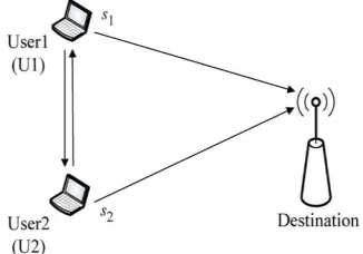
Fig 2. A decode-and-forward cooperation system with two cooperative users transmitting data to a common destination.
In this section, we first present the system
model used throughout this paper. Next, we
propose the O-DSTC schemes with full-duplex
and half-duplex considerations, which are
referred to as the full-duplex and
half-duplex-based O-DSTC, respectively. For the comparison
purpose, we also present the conventional S-DF.
As shown in Fig. 1, we consider a
cooperative diversity system consisting of two
cooperative users (as denoted by U1 and U2),
which assist each other using a DF protocol in
transmitting their information (i.e., and) to a
common destination, where the subscripts 1 and
2 represent U1 and U2, respectively. Although
only two cooperative users are considered in this
paper, this is an essential scenario to be
addressed, since a more generic scenario with
multiple source users can be typically converted
to the two-user cooperation by designing an
additional grouping and partner selection
protocol. In addition, each node as shown in Fig.
1 is assumed to have a single antenna, for which
two duplex modes (i.e., full-duplex and
half-duplex) are considered in the paper. It is pointed
out that full-duplex and half-duplex refer to the
antenna with and without the capability of
transmitting
and
receiving
a
signal
simultaneously
over
the
same
channel,
International Journal of Research (IJR)
e-ISSN: 2348-6848, p- ISSN: 2348-795X Volume 2, Issue 10, October 2015Available at http://internationaljournalofresearch.org
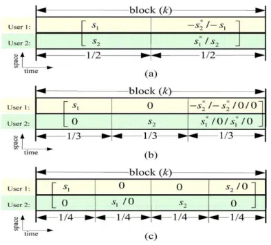
Fig. 2(a) illustrates that the proposed full-duplex-based O-DSTC scheme divides a total block into two time frames which are shared between U1 and U2. In the first time frame, both U1 and U2 exchange and transmit their own information and to the destination. At the same time, by considering the full-duplex regime, U1 and U2 can receive and decode each other’s information over the channels between the two users, called inter-user channels. In the subsequent time frame, U1 and U2 transmit and in an opportunistic encoding manner depending on whether U1 and U2 decode each other’s information successfully or not, One can observe from Fig. 2(a) that the full-duplex-based O-DSTC utilizes two time frames for transmitting two symbols (i.e., and), implying that full multiplexing gain (also known as full rate) is achieved. We will prove in following section that such an O-DSTC scheme also achieves the full diversity gain and, in contrast, the traditional fixed DSTC (F-DSTC) is unable to achieve full diversity due to the bottleneck effect caused by inter-user channels. Notice that, in the traditional F-DSTC scheme, either U1 or U2 failing to decoding its partner’s information will result in interferenceat the destination in decoding both the two users’ information.
In Fig. 2(b), we depict the half-duplex-based O-DSTC, where a total block is divided into three time frames. The difference between the full-duplex and half-duplex-based O-DSTC is that the former scheme utilizes one time frame to exchange the
information between U1 and U2, however the half-duplex-based O-DSTC requires two frames to complete the exchange process. From Fig. 2(b), one can see that, in the first two time frames, U1 and U2, respectively, broadcast and to each other and the destination. During the third time frame, U1 and U2 encode and transmit and using an opportunistic encoding approach, for which a detailed explanation will be presented in Section II-C. As shown in Fig. 2(b), the half-duplex-based O-DSTC uses three time frames for the transmission of and , thus a maximum multiplexing gain of two-third is achieved. This is very attractive as compared with the conventional S-DF cooperation and previous DSTC researches where a maximum multiplexing gain of only one-half is obtained.
Fig. 2(c) shows the conventional S-DF cooperation scheme as proposed in [4], where U1 and U2 are assisting each other’s data transmissions (i.e., and ) using four time frames. Specifically, in the first time frame of block, U1 broadcasts its own information to the destination and U2 that attempts to decode its received signal. Then, in the second time frame, U2 forwards its decoded outcome in a selective manner depending on whether it succeeds in decoding or not. If U2 decodesU1’s transmission successfully, it will forward to the destination. Otherwise, U2 just keeps silent in the second time frame. The process of transmitting during the remaining two time frames of block is essentially same as the procedure of transmitting in the first two frames. One can see from Fig. 2(c) that four time frames are used to complete the transmissions of and, implying that a maximum multiplexing gain of one-half only is achieved by the conventional S-DF cooperation.
2.2 FULL DUPLEX DISTRIBUTED SPACE-TIME CODING (H-DSTC) SCHEMES
International Journal of Research (IJR)
e-ISSN: 2348-6848, p- ISSN: 2348-795X Volume 2, Issue 10, October 2015Available at http://internationaljournalofresearch.org
accessing the time frames to transmit their own data with power at data rates and in bits per frame, respectively. One can see from Fig. 2(a) that, in the full-duplex- based O-DSTC, two independent symbols and are transmitted by using two time frames, which means that no extra channel resource is wasted by retransmission. Thus, when U1 and U2, respectively, transmit at data rates and in the full-duplex-based O-DSTC scheme, it is guaranteed to transmit the same amount information (during one block) as the non-cooperative scheme. However, the proposed full-duplex-based O-DSTC scheme requires both U1 and U2 always transmitting in two frames during one block, differing from non-cooperative scheme where U1 and U2 take turns in the time block to transmit their information. Hence, for a fair comparison with the non-cooperative transmission in terms of power consumption, we consider one-half power ES/2 for each user during one time frame in the full-duplex-based O-DSTC scheme. Accordingly, the received signal at the destination in the first time frame of block k is expressed as
1 2 2 2 1 1 2 1
d n s d h s E s d h s E
d
y
Where the superscript 1 represents the first time frame of block k, h1d and h2d are fading
coefficients of the channel from U1 to destination and that from U2 to destination, respectively, and
𝑛𝑑1represents AWGN with zero mean and variance N0. Note that the fading coefficients are modeled as
constant during one block (including two frames for full-duplex-based O-DSTC) and vary independently in next time block. Meanwhile, the full-duplex enables U1 and U2 to receive and decode each other’s information over the inter-user channels at the same time. Hence, the received signals at U1 and U2 are, respectively, given by
1 2 21 2
1 h s n
s E
y
Where h21 represents the channel from U2 to U1 and n1 is AWGN with zero mean and variance N0, and
2 1 12 2
2 h s n
s E
y
Where h12 represents the channel from U1 to U2 and n2 is AWGN with zero mean and variance N0. Then, U1 and U2 decode each other’s information using their received signals as given by (2) and (3), respectively. For the full-duplex-based O-DSTC scheme, we consider that U1 and U2 will acknowledge each other and the destination if they succeed in decoding or not using feedback channels. It is assumed that both U1 and U2 always decode the
acknowledgement information successfully,
considering the fact that an acknowledgment consists of only one-bit information. In the second time frame of block , U1 and U2 encode and transmit s1 and s2 in an opportunistic manner depending on their decoded outcomes in the first frame. To be specific, if both U1 and U2 decode each other’s information successfully, the Alamouti space-time coding [13] will be utilized, i.e.,-S*2 and S*1 are transmitted by U1 and U2, respectively. Otherwise, U1 and U2, respectively, transmit –S1 and S2 to the destination, instead of the Alamouti coding. This is due to the fact that, when either U1 or U2 fails to decode, the use of Alamouti space-time code will introduce interference at the destination in decoding S1 and S2. Meanwhile, the destination cannot rely on its received signal in the first frame to decode S1 and S2, since two unknowns (S1 and S2) are in one equation, as shown in (1). In order to recover S1 and S2 at the destination in this case, U1 and U2 are allowed to transmit –S1 and S2 , respectively, to the destination in the second time frame, which guarantees the full multiplexing gain achieved and has the advantage of simple implementation for decoding S1 and S2 at the destination. The mutual information from U2 to U1 as denoted by can be calculated from (2) as
2 1 log 21
2 21 2
h I
(1)
(2)
(3)
International Journal of Research (IJR)
e-ISSN: 2348-6848, p- ISSN: 2348-795X Volume 2, Issue 10, October 2015Available at http://internationaljournalofresearch.org
2 1 log 12 2 12 2 h I
In an information-theoretic sense, when the channel capacity falls below a predefined data rate, it is regarded as an outage event and the receiver is doomed to fail to decode the original data no matter what decoding algorithm is used. Hence, considering data rates R1 and R2 (for U1 and U2, respectively), the event that both U1 and U2 succeed in decoding can be described as I12>R1 and I21>R2, which is denoted by for notation convenience. Similarly, we use to represent the other case that either U1 or U2 or both fail to decode, i.e., I12<R1 and/or I21<R2. In the case of , the Alamouti space-time coding will be utilized, and –S*1 and S*2 are transmitted by U1 and U2 in the second time frame of block k. Thus, the received signal at the destination is written as
22 2 1 2 1 2 * 1 *
2 h ds nd
s E s d h s E d
y
Where the superscript 2 represents the second time
frame and
2
d
n
is the AWGN received at destination. Combining (1) and (6), we can obtain from Alamouti decoding algorithm as
2*
1 1 * 2 * 2 2 1 * 1 2 1 2 2 2 1 2 2 2 1 * 2 1 1 * 2 2 * 1 ) ( ) ( 0 0 2
1 d d d d
d d d d d d d d s d d d d d d n h n h n h n h s s h h h h E y y h h h h
The mutual information from U1 and U2 to the destination is calculated from (7)
2 1 log 1 1 2 2 2 1 2 2 1 d d d d h h I I
U1 or U2 or both fail to decode each other’s information, U1 and U2, respectively, transmit –s1 and s2 to the destination. The received signal at the destination in the second time frame is given by
2
2 2 1 2 2 2 2
1 hds nd
s E s d h s E θ d
y
By solving (1) and (9), the destination can easily decode s1 and s2 as follows
* 2 1 * 2 2 1 * 1 2 2 2 1 2 1 2 1 2 1 * 2 * 1 ) ( ) ( 2 2 1 2 0 0 d d d d d d d s d s d d d d d d n n h n n h s h E s h E y y y y h h
From which s1 and s2 are estimated as
21 2
1 *
1 2 2
min arg 2 s E h y y
hd d d d s
s
s
and
22 2
1 *
2 2 2
min arg 2 s E h y y
hd d d d s
s
s
by using the
maximum likelihood (ML) detection.
2
1 2
1d 2 log 1 hd
I
and
2
2 2
2d 2 log 1 hd
I
In addition, it is pointed out that, by considering that both U1 and U2 notify the destination whether or not they succeed in decoding each other’s information through feedback channels, the destination is able to determine which detection algorithm should be selected between (7) and (10) and used for decoding s1 and s2.
2.3 HALF DUPLEX DISTRIBUTED SPACE-TIME CODING (H-DSTC) SCHEMES
This subsection discusses the half-duplex-based O-DSTC scheme. One can see from Fig. 2(b) that in the half-duplex- based O-DSTC scheme, three time frames within one block are required to transmit two symbols s1 and s2. In order to send the same amount information as the non-cooperative scheme during one block, the half-duplex-based O-DSTC scheme shall transmit at 1.5 times data rate of the non-cooperative transmission. Thus, we consider U1
International Journal of Research (IJR)
e-ISSN: 2348-6848, p- ISSN: 2348-795X Volume 2, Issue 10, October 2015Available at http://internationaljournalofresearch.org
and U2 with data rates
2
3
R
1and
2
3
R
2in bits per
frame, respectively, for the half-duplex-based O-DSTC. In addition, as shown in Fig. 2(b), the half-duplex-based O-DSTC scheme divides one block into three time frames and requires both U1 and U2 to transmit in either one or two frames per block. Assuming the worst case of the two users transmitting in two frames per block, we consider the power of
4
3
E
sfor each user during one time frame in the
half-duplex-based O-DSTC scheme for a fair comparison with the non-cooperative scheme in terms of power consumption.
In the first time frame of block k, U1
broadcasts its signal with power
4
3
E
sand rate
4
3
R
1to U2 and destination. Thus, the received signals at the destination and U2 are expressed as
1 1 1 4 3 1
d n s d h s E
d
y
and
2 1 12 4 3
2 h s n
s E
y
Similarly, in the second time frame, U2 transmits to
U1 and destination with power
4
3
E
sand rate
4
3
R
2.
Hence, the received signals at the destination and U1 are given by
2 2 2 4 3 2
d n s d h s E
d
y
and
1 2 21 4 3
1 h s n
s E
y
Then, U1 and U2 attempt to decode their received signals based on (14) and (16), respectively. In the third time frame of block, the transmit symbols
sent by U1 and U2 depend on their local decoded outcome without any acknowledgment (feedback) between each other. Specifically, if U1 succeeds in decoding U2’s information, it will transmit; otherwise, it just keeps quiet to avoid interference. Similarly, if U2 succeeds in decoding, it will transmit to the destination; otherwise, no signal is transmitted. Hence, there are four possible outcomes at the destination which requires respective decoding algorithms. As shown in Fig. 3,we can implement four decoding branches in parallel at the destination and, in general, only one branch output will pass the forward error detection (e.g., CRC checking). This means that the destination can decode and locally without any feedback information from U1 and U2 about whether the two users decode each other’s information successfully or not. This advantage comes at the cost of implementation complexity due to the parallel decoding architecture. It is pointed out that, if feedback channels are available for U1 and U2 to notify the destination whether they succeed in decoding or not, the multiple parallel decoding branches as illustrated in Fig. 3 can be reduced to a single branch structure.
With the coherent detection, the mutual information from U2 to U1 and that fromU1 to U2 are calculated from (14) and (16) as
4 3 1 log
2
1 2
1
d d
h I
and
4 3 1 log
2
21 2
21
h I
As discussed above, there are four possible outcomes with regard to whether U1 and U2 succeed in decoding each other. For simplicity, let
=1, 2, 3, and 4, respectively, denote U1 and U2 decode successfully, U1 succeeds and U2 fails, U1 fails and U2 succeeds, and both fail. Hence, in an information-theoretic sense, events
= 1, 2, 3, and 4 are described as(13)
(14)
(15)
(16)
(17)
International Journal of Research (IJR)
e-ISSN: 2348-6848, p- ISSN: 2348-795X Volume 2, Issue 10, October 2015Available at http://internationaljournalofresearch.org
2 3 2
3 :
1 2
21 1
12
R I and R
I
2
3
2
3
:
2
221 1
12
R
I
and
R
I
2 3 2
3 :
3 2
21 1 12
R I and R
I
2 3 2
3 :
4 2
21 1
12
R I and R
I
In the case of
1
, -S2 *and S1 *
are transmitted by U1 and U2 in the third time frame of block Thus, the received signal at the destination in this case is written as
a
d n s d h s E s d h s E
d
y 3
2 4 3 1 4 3 1
3 *
1 *
2
Where is AWGN with zero mean and variance N0. By
using (13), (15) and (20), S1 and S2 are demodulated
at the destination as follows
where
n
d'
n
1d
n
d2. Note that the motivation ofusing
y
d1
y
d2 jointly with is to employ the Alamouti decoding algorithm to decode the desired signals S1 and S2. One can see that the first matrix in (21) is the exact Alamouti decoding matrix which is also used in (7) for the full-duplex-based O-DSTC scheme. It is pointed out that the decoding strategy adopted in (21) has low computational complexity and preserves the full diversity, as will be shown later in (66). Hence, given
1
, the mutual information from U1 and U2 to the destination calculated from (21) asGiven
2
occurred, i.e., U1 succeeds in decoding S2 from (16) and U2 fails to decode S1 from (14), U1 transmits -S2* and U2 keeps quiet during the third time frame of block. Therefore, in the case of2
, the received signal at the destination is given by 3
1 4 3 2
3 *
2 nd s d h s E
d
y
Using (13), (15) and (24), the destination will decode and S1 as S2 follows
Hence, given
2
, the mutual information from U1 to the destination and that from U2 to the destination are given by
4 3 1 log ) 2 (
2 1 2 1
d
d
h I
Note that case
2
occurs when the channel from U1 to U2 is in outage. Thus, the destination will fail to decode S1 only when both the channels from U1 toU2 and that from U1 to destination are in outage. This implies that a diversity gain of two is still achieved by the U1’s transmissions given
2
, which will be proven in Section IV. In the case of2
, i.e., U1 fails to decode S2 from (16) and U2succeeds in decoding S1 from (14), U1 keeps quiet
and U2 transmits S*1 in the third time frame of block .
Hence, given
2
, the received signal at the destination can be given by(19)
(20)
(21)
(22)
(23)
(24)
(25)
(26)
(27)
International Journal of Research (IJR)
e-ISSN: 2348-6848, p- ISSN: 2348-795X Volume 2, Issue 10, October 2015Available at http://internationaljournalofresearch.org
Combining (13), (15), and (28), the destination can decode S1 and S2 as given by
from which the mutual information from U1 and U2 to the destination can be calculated as
The last case
4
indicates that both U1 and U2 fail to decode each other’s information. In this case, the destination can only rely on (13) and (15) to decode S1 and S2, respectively. Thus, thecorresponding mutual information from U1 and U2 to destination are given by
2.4 OUTAGE PROBABILITY ANALYSIS OVER RAYLEIGH FADING CHANNELS
In this section, we examine the outage probability for full-duplex O-DSTC schemes as well as the conventional S-DF and F-DSTC. We only focus on the performance analysis of the transmission of s1 from U1 to destination throughout this paper, and similar performance results can be obtained for the transmission of s2 from U2 to destination. Let us first consider the traditional non-cooperative scenario in a Rayleigh fading environment, where the outage probability of U1’s transmissions with power ES and rate R1 is given by
2 1 1 1 2 1 2 1 2 exp 1 1 log Pr d R dnon h R
Pout
Outage Analysis of Full-Duplex Based O-DSTC Scheme: the full-duplex-based O-DSTC scheme utilizes an opportunistic encoding approach depending on whether U1 and U2 succeed in decoding each other’s information. Following (8) and (11), an outage probability of the U1’s transmission can be expressed as
) 2 | Pr( ) 2 Pr( ) 1 | Pr( ) 1
Pr(
outage outage
Poutfill ODSTC
1 Pr( , )Pr( 2 ) ) 1 Pr( ) , Pr( 1 1 2 21 1 12 1 1 2 21 1 12 R I R I R I R I R I R I d d
Where I21, I12,
1
1d
I , and I1d
2
are, respectively, given by (4),(5),(8) and (11). Thefollowing closed form solutions to term
) ,
Pr(I12R1 I21R2 is given by
2 12 2 12 2 21 1 12 1 2 2 exp 1 2 2 exp ) , Pr( 2 1 R R R I R IUsing (8), we can calculate Pr( 1 )
1
1 R
Id as
1 ) Pr 22 1
Pr( 1 2 2 2 1 1 1 R d d
d R h h
I
otherwise X d R d d d d R d d d d d d R d R , 1 2 2 exp 1 2 2 exp 1 , 1 2 2 exp 1 2 2 1 1 2 1 2 1 2 2 2 2 2 1 2 2 2 1 2 1 2 2 2 1 2 1 2 1 1 1 1 1 Similarly, substituting (11) into termPr( 2 )
1
1 R
Id ,
we easily obtain
2 1 1 1 1 2 2 exp 1 2 Pr 1 d R d R I
Now, we complete the closed-form outage probability analysis for the full-duplex-based O-DSTC scheme.
Outage Analysis of Full-Duplex Based
F-DSTC Scheme: Distributed Alamouti space-time
coding to achieve the cooperative diversity, no matter whether U1 and U2 decode each other’s information successfully or not. To be specific, in the first time
International Journal of Research (IJR)
e-ISSN: 2348-6848, p- ISSN: 2348-795X Volume 2, Issue 10, October 2015Available at http://internationaljournalofresearch.org
frame of block , both U1 and U2 transmit their own information s1 and s2 to the destination with power ES/2. Considering the full-duplex regime, U1 and U2 can receive and decode each other’s information, where the decoded outcomes at U1 andU2 are denoted by 𝑠 2and 𝑠 1, respectively. Then, in the subsequent time frame, U1 and U2 transmit their decoded outcomes according to the Alamouti
space-time coding, i.e.,
s
ˆ
2* and
s
ˆ
1*are forwarded to the destination.which can be further rewritten as
By applying the Alamouti decoding to (40),
The destination attempts to decode s1 and s2 as shown in (18) at the bottom of the page. One can observe from the second term in the right-hand side (RHS) of (18) that either U1 or U2 or both failing to decode will lead to 𝑠 1≠ 𝑠1 and/or 𝑠 2≠ 𝑠2, which results in interference at the destination in decoding both s1 and s2, and severely degrades the transmission performance. This also implies that the inter-user channels between U1 and U2 are the bottleneck of the traditional F-DSTC scheme.
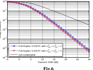
Numerical Results: We present the outage probability comparison of the proposed full-duplex-based
O-DSTC scheme with the traditional non-cooperative and the full-duplex-based F-DSTC schemes. In Fig. 4, we show the outage probability performance versus transmit SNR of the non-cooperative, the full-duplex-based F-DSTC and O-DSTC schemes with R1 = R2 = 1 bits/s/Hz. As shown in Fig. 4, the proposed O-DSTC scheme strictly outperforms both the non-cooperative and the F-DSTC schemes in terms of the outage probability across the whole SNR region. One can also see from Fig. 4 that, in the low SNR region, the outage probability of the F-DSTC scheme is even worse than that of the non-cooperative transmission. On the other hand, in high SNR region, as the transmit SNR increases, the outage probability of the F-DSTC scheme decreases at the same speed as the non-cooperative transmission. However, the outage probability decrease of the proposed O-DSTC scheme is at higher speed than both the F-DSTC and non-cooperative schemes. This implies that the proposed O-DSTC achieves higher diversity order (also known as diversity gain).
Outage Analysis of Half-Duplex Based O-DSTC: In this subsection, we study the outage probability performance of the proposed half-duplex-based O-DSTC scheme. An outage probability of the U1’s transmission with the half-duplex-based O-DSTC scheme is calculated as
In the following, we examine closed-form solutions to these terms as given in the RHS of the above equation.
(40)
(41)
(39)
International Journal of Research (IJR)
e-ISSN: 2348-6848, p- ISSN: 2348-795X Volume 2, Issue 10, October 2015Available at http://internationaljournalofresearch.org
This completes a closed-form outage probability analysis for the proposed half-duplex-based O-DSTC scheme. In what follows, we present an outage analysis of the traditional F-DSTC scheme with the duplex relaying, referred to as the half-duplex based F-DSTC.
DIVERSITY-MULTIPLEXING TRADEOFF
ANALYSIS
In this section, we conduct the DMT analysis for the proposed full-duplex and half-duplex-based O-DSTC schemes. The diversity gain of a wireless transmission system can be defined as
log
log lim Pout
d
Where
Pout
represents an outage probability ofthe wireless transmission system and
is thetransmit SNR. Meanwhile, given multiplexing gains r1 and r2, the date rates of U1 and U2 (i.e., R1 and R2) are given by
1log
21
1
r
R
and
2log2 12 r
R
FULL-DUPLEX-BASED O-DSTC SCHEME
Considering
and following (35), wecalculate an outage probability limit of the full-duplex-based O-DSTC scheme as
ODSTC full
Pout
lim
12 1, 21 2
limPr
1
1
1
Pr
lim I R I R I d R
( 2)
. Prlim
, Pr
lim 1
1 1
2 21 1 21
R I
x
R I R I
d
The DMT of the full-duplex-based O-DSTC scheme is obtained as
Which shows that a maximum diversity gain of two is obtained as (r1,r2) 0. One can observe from (64) that the diversity gain of U1 not only depends on its own multiplexing gain r1, but also relates to its partner’s multiplexing gain r2. This reason is that, either U1 or U2 increases the multiplexing gain (i.e., higher data rate), it decreases the probability of occurrence of case
1
and increases the occurrence probability of the other case
2
. Moreover, under cases
1
and 2, different diversity gains are achieved by U1 as implied from (8) and (11), which finally leads to the fact that the diversity gain of U1 depends on both r1 and r2. From (50), given a U1’s multiplexing gain r1, the diversity gain of the U1’s transmissions can be maximized when r2 <. r1 Also, one can imagine that given r2 , the diversity gain of theU2’s transmissions is given by 2-r2-max(r1,r2), which is maximized with r1<r2. Therefore, by jointly considering U1 and U2, an optimal DMT of the proposed full-duplex-based O-DSTC scheme is achieved when r1= r2.HALF-DUPLEX-BASED O-DSTC SCHEME
We investigate the DMT performance of the
half-duplex- based O-DSTC scheme. Letting
and following, we can obtain.3 / 2 0
, 2
31 1
r r
dhalf ODSTC
This shows that a maximum diversity gain of two is obtained as the multiplexing gain approaches zero. One can also observe from (50) that the diversity gain achieved by U1 only depends on its own multiplexing
(43)
(44)
(45)
(46)
(49)
(50)
(47)
(48)
International Journal of Research (IJR)
e-ISSN: 2348-6848, p- ISSN: 2348-795X Volume 2, Issue 10, October 2015Available at http://internationaljournalofresearch.org
gain and has nothing to do with its partner’s multiplexing gain. This is because that the U2’s multiplexing gain only affects U1 in decoding U2’s information. However, no matter whether U1 succeeds in decoding U2’s information or not, the diversity gain of U1 keeps unchanged
1 ) , max(1 2 2
3
r r
dhalf FDSTC
Where 0 2/3
1
r and 0 2/3
2
r . As shown in (52), a maximum diversity gain of only one is achieved. Moreover, mutual dependence between U1 and U2 exists in terms of DMT performance, which arises from the fact that either U1 or U2 failing to decode would result in interference at the destination in decoding both users’ information. As shown in (51).
3.SIMULATION RESULTS
We present the outage probability
comparison of the proposed full-duplex-based O-DSTC scheme with the traditional non-cooperative and the full-duplex-based F-DSTC schemes. In Fig. 11, we show the outage probability performance versus transmit SNR of the non-cooperative, the full-duplex-based F-DSTC and O-DSTC schemes with R1 = R2 = 1 bit/s/Hz.
Fig. 11. Outage probability versus transmit SNR of the non-cooperative, the half-duplex-based O-DSTC
schemes with R1=R2=1 bit/s/Hz and
1
2 2 2
1d
d
Fig.3 Outage probability of O-DSTC and non-cooperative network
Fig 4 Outage probability versus transmit SNR of the non-cooperative and the half-duplex-based O-DSTC schemes for different multiplexing gains of U1 and U2 (and) with
1
2 2 2
21 2
1 2
12
d
d
Fg.5. Outage probability of O-DSTC for different multiplexing gain
The outage probability of the O-DSTC scheme decreases at the same speed as the non-cooperative in high SNR region, which shows that no diversity gain is achieved by U1’s transmissions given the U2’s multiplexing gain r2 = 1 . As decreases from r2 = 1 to 0.4,
the speed of the outage probability decrease in high SNR region improves.
We present the outage probability comparison of the proposed full-duplex-based O-DSTC scheme with the traditional non-cooperative and the full-duplex-based F-DSTC schemes. In Fig. 4, we show the outage probability performance versus transmit SNR of the non-cooperative, the full-duplex-based F-DSTC and O-DSTC schemes with
R1 = R2 = 1 bit/s/Hz.
Fig.6
-5 0 5 10 15 20 25 30 10-6
10-5
10-4
10-3 10-2 10-1
100 HALF DUPLEX O-DSTC
Transmit SNR (dB)
O
ut
ag
e
pr
ob
ab
ili
ty
Half-Duplex O-DSTC with 12 2 =
12 2 = 1
Half-Duplex O-DSTC with 12 2 =
21 2 = 2
non-cooperative
0 5 10 15 20 25 30 35 40 45 50 10-6
10-5 10-4 10-3 10-2 10-1 100
Transmit SNR(dB)
O
u
ta
g
e
p
ro
b
a
b
ili
ty
Half-Duplex O-DSTC with (r
1,r2) =(0.4,2/3)
Half-Duplex O-DSTC with (r
1,r2) =(0.4,0)
Half-Duplex O-DSTC with (r
1,r2) =(0.3,2/3)
Half-Duplex O-DSTC with (r
1,r2) =(0.3,0)
non-cooperative with r
1=0.4
-5 0 5 10 15 20 25 30 10-6
10-5 10-4 10-3 10-2 10-1 100
Transmit SNR (dB)
O
u
ta
g
e
p
ro
b
a
b
ili
ty
Full-Duplex O-DSTC with 122 = 122 = 1 Full-Duplex O-DSTC with 12
2
= 21 2
= 2 non-cooperative
International Journal of Research (IJR)
e-ISSN: 2348-6848, p- ISSN: 2348-795X Volume 2, Issue 10, October 2015Available at http://internationaljournalofresearch.org
Fig.7
The outage probability of the O-DSTC scheme decreases at the same speed as the non-cooperative in high SNR region, which shows that no diversity gain is achieved by U1’s transmissions given the U2’s multiplexing gain r2 = 1 . As
decreases from r2 = 1 to 0.4, the speed of the outage
probability decrease in high SNR region improves. Outage probability versus transmit SNR of the non-cooperative, the half-duplex-based F-DSTC and O-DSTC schemes with
R1=R2=1 bit/s/Hz and
1
2 2 2
1d
d
Fig.8.
Outage probability versus transmit SNR of the non-cooperative, the half-duplex-based F-DSTC and O-DSTC schemes with R1=R2=2 bit/s/Hz and
1
2 2 2
1d
d
Fig.9.
Above figure shows a DMT comparison among the half-duplex-based O-DSTC, and the full-duplex-based O-DSTC schemes with r1 = r2. Notice that the DMT curve of the non-cooperative scheme is identical to that of the full-duplex- based F-DSTC scheme. It was shown that, no matter which duplex mode (i.e., full-duplex and half-duplex) is considered, the proposed O-DSTC scheme strictly outperforms the conventional S-DF and F-DSTC schemes.
CONCLUSION
In this paper, we explored O-DSTC for DF cooperation systems. We proposed the full-duplex
and half-duplex-based O-DSTC schemes and
evaluated their outage probability performance over Rayleigh fading channels. For the comparison purpose, we conducted an outage analysis for the non-cooperative, the conventional S-DF cooperation, and the full-duplex and half-duplex-based fixed DSTC (F-DSTC) schemes. Numerical results showed that the proposed O-DSTC scheme outperforms the conventional S-DF and F-DSTC schemes in terms of the outage probability considering both the full-duplex and half-full-duplex modes. In addition, we examined the DMT of the full-duplex and half-duplex-based O-DSTC and F-DSTC schemes as well as the conventional S-DF cooperation. It was shown that, no matter which duplex mode (i.e., full-duplex and half-duplex) is considered, the proposed O-DSTC scheme strictly outperforms the conventional S-DF and F-DSTC schemes. We also illustrated that, in the
full-duplex-based O-DSTC scheme, mutual
dependence exits between two cooperative users in terms of DMT. However, for the half-duplex- based O-DSTC scheme, the DMT performance of the two users are independent of each other, i.e., the diversity
0 5 10 15 20 25 30 35 40 45 50 10-12
10-10 10-8 10-6 10-4 10-2 100
Transmit SNR (dB)
O
ut
ag
e
pr
ob
ab
ili
ty
Non-cooperative
Full-Duplex O-DSTC with r2=1 Full-Duplex O-DSTC with r2=0.8 Full-Duplex O-DSTC with r2=0,6 Full-Duplex O-DSTC with r2=0.4 Full-Duplex O-DSTC with r2=0
-5 0 5 10 15 20 25 30 10-5
10-4 10-3 10-2 10-1 100
Transmit SNR (dB)
O
u
ta
g
e
p
ro
b
a
b
ili
ty
outage prob. with R1=R2=2 bit/sec
Half-Duplex O-DSTC with 12 2 =
12 2 = 1
Full-Duplex O-DSTC with 122 = 12 2 = 1
non-cooperative
0 0.1 0.2 0.3 0.4 0.5 0.6 0.7 0.8 0.9 1 0
0.2 0.4 0.6 0.8 1 1.2 1.4 1.6 1.8 2
multiplexing gain (r1=r2)
di
ve
rs
ty
g
ai
n
Diversity multiplexing Tradeoffs
International Journal of Research (IJR)
e-ISSN: 2348-6848, p- ISSN: 2348-795X Volume 2, Issue 10, October 2015Available at http://internationaljournalofresearch.org
gain of a user only relates to its own multiplexing gain.
REFERENCES
[1] R. T. Derryberry, S. D. Gray, D. M. Lonescu, G. Mandyam, and B. Raghothaman, ―Transmit
diversity in 3G CDMA systems,‖ IEEE
Commun. Mag., vol. 40, no. 4, pp. 68–75, Apr. 2002.
[2] A. Nosratinia and T. E. Hunter, ―Cooperative communication in wireless networks,‖ IEEE Commun. Mag., vol. 42, no. 10, pp. 74–80, 2004.
[3] A. Sendonaris, E. Erkip, and B. Aazhang, ―User
cooperation diversity— Part I: System
description,‖ IEEE Trans. Commun., vol. 51, no. 11, pp. 1927–1938, 2003.
[4] J. N. Laneman, D. N. C. Tse, andG.W.Wornell, ―Cooperative diversity in wireless networks: Efficient protocols and outage behavior,‖ IEEE Trans. Inf. Theory, vol. 50, pp. 3062–3080, Dec. 2004.
[5] T. E. Hunter, S. Sanayei, and A. Nosratinia, ―Outage analysis of coded cooperation,‖ IEEE Trans. Inf. Theory, vol. 52, no. 2, pp. 375–391, Feb. 2006.
[6] K. Azarian, H. E. Gamal, and P. Schniter, ―On the achievable diversity- multiplexing tradeoff in half-duplex cooperative channels,‖ IEEE Trans. Inf. Theory, vol. 51, pp. 4152–4172, Nov. 2005.
[7] E. G. Larsson and B. R. Vojcic, ―Cooperative transmit diversity based on superposition modulation,‖ IEEE Commun. Lett., vol. 9, pp. 778–780, Sep. 2005.
[8] Z. Ding, T. Ratnarajah, and C. C. F. Cowan, ―On the diversity-multiplexing tradeoff for wireless cooperative multiple access systems,‖ IEEE Trans. Signal Process., vol. 55, no. 9, pp. 4627– 4638, Sep. 2007.
[9] S. Wei, ―Diversity-multiplexing tradeoff of asynchronous cooperative diversity in wireless
networks,‖ IEEE Trans. Inf. Theory, vol. 53, no. 11, pp. 4150–4172, Nov. 2007.