International Journal of Research (IJR)
e-ISSN: 2348-6848, p- ISSN: 2348-795X Volume 2, Issue 10, October 2015Available at http://internationaljournalofresearch.org
Robust license-plate recognition System using Vertical edge
detection algorithm
1
Dr.K.SRI HARI RAO
M.E, PHD, Professor and Head of the Dept of ECE, NRIIT, GUNTUR, Andhra Pradesh, Email: [email protected]
2
bodipudi Greeshma
M.tech Student, Digital Electronics And Communication Systems, NRIIT, GUNTUR, Andhra Pradesh, Email:[email protected]
ABSTRACT:
The car-license-plate (CLP) recognition system is an image processing technology issued to identify vehicles by capturing their CLPs .The CLP recognition technology is known as automatic number-plate recognition, automatic vehicle identification CLP for cars. In the
previous work on” Robust license-plate
recognition method for passing vehicles under outside environment”, numerous vehicle tracking and pursue systems use outstanding cameras.
The scheme has three contributions: The Vertical edge detection algorithm (VEDA) is proposed and used for detecting vertical edges. The color input image is converted to a grayscale image and then, adaptive threshold (AT) is applied on the image to constitute the binaries image. After that, the Unwanted-line elimination algorithm is applied to remove noise and to enhance the binaries image. Then the vertical edges are extracted by using the VEDA. The next process is to detect the LP; the plate details are highlighted based on the pixel value with the help of the VEDA output. Then, some statistical and logical operations are used to detect candidate regions and to search for the true candidate region. Finally, the true plate region is detected in the original image.
1.Introduction
Recent improvements in technology like infrared imaging and high resolution cameras, and
utilization of high reflective backgrounds in license plate manufacturing have improved the accuracy of LPR systems. Sensors and other hardware peripherals are used to improve the image acquisition and remove irrelevant details. New video frame grabbers enable fast digitization of acquired images and new computers with proper LPR software render the system operable in real-time with high precision and accuracy. After the recognition process, the extracted information can be further verified through local or remote databases and stored for future referencing.
A typical LPR system is composed of several hardware and software components.
A typical LPR system operates as follows. When the vehicle approaches the secured area or gate, it starts the cycle by stepping over a magnetic loop detector (which is the most popular vehicle sensor). The loop detector senses the car and sends signals to the LPR unit. The LPR unit activates the illumination (invisible Infra-red in most cases) and takes pictures of the front or rear plates from the LPR camera. The images of the vehicle include the plate and the pixel information is read by the LPR unit's image processing hardware (the frame grabber). The LPR unit analyzes the image with different image processing software algorithms, enhances the image, detects the plate position, extracts the plate string, and identifies the fonts using special
artificial intelligence methods (such as
International Journal of Research (IJR)
e-ISSN: 2348-6848, p- ISSN: 2348-795X Volume 2, Issue 10, October 2015Available at http://internationaljournalofresearch.org
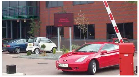
The extracted license plate information can be logged, stored along with the captured image or used for authentication depending on the LPR
application. The LPR unit activates the
illumination (invisible Infra-red in most cases) and takes pictures of the front or rear plates from the LPR camera (shown at the left side of the gate). The images of the vehicle include the plate and the pixel information is read by the LPR unit's image processing hardware (the frame grabber). The vehicle approached the secured area, and starts the cycle by stepping over a magnetic loop detector (which is the most popular vehicle sensor). The loop detector senses the car and its presence is signaled to the LPR unit.
Fig 1 Car Recognition.
The Fig 1 shows that recognition is not absolute and may contain errors due to problems in any of the LPR stages. Applications need to employ proper verification and control methods in order to compensate for the potential problems. If the application is sensitive to errors (e.g. toll collection), license plates that are not correctly identified are processed manually.
This technology is gaining popularity
in security and traffic installations. The
technology concept assumes that all vehicles already have the identity displayed (the plate!) so no additional transmitter or responder is required to be installed on the car. The system uses illumination (such as Infra-red) and a camera to take the image of the front or rear of the vehicle, then an image-processing software analyzes the images and extracts the plate information. This data is used for enforcement, data collection, and
(as in the access-control system featured above) can be used to open a gate if the car is authorized or keep a time record on the entry or exit for automatic payment calculations.
The LPR system significant advantage is that the system can keep an image record of the vehicle which is useful in order to fight crime and fraud ("an image is worth a thousand words"). An additional camera can focus on the driver face and save the image for security reasons. Additionally, this technology does not need any installation per car (such as in all the other technologies that require a transmitter added on each car or carried by the driver).Early LPR systems sufferred from a low recognition rate, lower than required by practical systems.
The external effects (sun and headlights, bad plates, wide number of plates types) and the limited level of the recognition software and vision hardware yielded low quality systems. Early LPR systems sufferred from a low recognition rate, lower than required by practical systems. The external effects (sun and headlights, bad plates, wide number of plates types) and the limited level of the recognition software and vision hardware yielded low quality systems.
However, recent improvements in the software and hardware have made the LPR systems much more reliable and wide spread. You can now find these systems in numerous installations and the number of systems are growing exponentially, efficiently automating more and more tasks in different market segments. In many cases the LPR unit is added as retrofit in addition to existing solutions, such as a magnetic card reader or ticket dispenser/reader, in order to add more functionality to the existing facility.
International Journal of Research (IJR)
e-ISSN: 2348-6848, p- ISSN: 2348-795X Volume 2, Issue 10, October 2015Available at http://internationaljournalofresearch.org
exit time in order to establish the parking time, the match (of entry verses exit) can allow some small degree of error without making a mistake. This intelligent integration can overcome some of the LPR flaws and yield dependable and fully automatic systems
2.Methodology
2.1VERTICAL EDGE DETECTION
ALGORITHM
This paper has three contributions: VEDA is proposed and used for detecting vertical edges, the proposed CLPD method processes low quality images produced which has a resolution of 352×288 with 30 fps, and the computation time of the CLPD method is less than several methods. In this project, the color input image is converted to gray-scale image and then, adaptive thresholding is applied on the image in order to constitute the binarized image. After that, ULEA is applied in order to remove noise and enhance the binarized image. Next, the vertical edges are extracted by using VEDA. The next process is to detect the license plate; the plate details are highlighted based on the pixel value with help of VEDA output. Then, some statistical and logical operations are used in order to detect candidate regions and search for the true candidate region. Finally, the true plate region is detected in the original image.
We can see that vertical edge detector is better than horizontal edge detector in suppressing horizontal noise. Before vertical edge detection, a linear filter is used to smooth the Image apply the illuminance normalization to reduce the influence of light. In this type of a mask, it is divided into three submasks:
The first submask is the left mask “2 × 2,” the
second submask is the center “2 × 1,” and the
third submask is the right mask “2 × 1,” as
marked in . Simply, after each two pixels are checked at once, the first submask is applied so that a 2 pixel width “because two column are processed” can be considered for detecting. This
process is specified to detect the vertical edges at
the intersections of black–white regions.
Similarly, the third submask is applied on the intersections of white–black regions. Thus, the detected vertical edge has the property of a 1 pixel width.
The number “2” points out the number of rows that are checked at once. The consumed time in this case can be less twice in case each row is individually checked. To select the column at locations (0, 1) and (1, 1) to be the center of the proposed mask, two pixels and one pixel inthe case of black–white and white–black regions are retained, respectively. This process is performed for both of the edges at the left and right sides of the object-of-interest. The first edge can have a black-pixel width of 2, and the second edge can have ablack-pixel width of 1.
The 21 × 4 mask starts moving from top to
bottom and from left to right. If the four pixels at locations(0, 1), (0, 2), (1, 1), and (1, 2) are black, then the other mask values are tested if whether they are black or not.
If the whole values are black, then the two locations at (0, 1) and (1, 1) will be converted to white.The whole tested images are 664, and they are classified into three groups
based on the images quality, background complexity, and lighting effects. The first group (G1) includes the ideal, blurry, and defected plates. The second group (G2) contains double-rowLPs, trees, similarity of LP and car body, and more than one LP or a car in a single image. The third group (G3) contains excessive light, rainy, shady, and low-contrast images. Table IIIshows the number of images per each classified group. To show the increment percentage of the detection rate, shows the detection rate of each group before and after
applying .
International Journal of Research (IJR)
e-ISSN: 2348-6848, p- ISSN: 2348-795X Volume 2, Issue 10, October 2015Available at http://internationaljournalofresearch.org
lower than G1 due to the complexity existing in the image. This shows the percentage of success and failure for each group. This shows the average processing times for all test images. Most of the processed images take 47 ms. The computation time for each of the seven stages in the proposed method .
A lot of the time is consumed on the second stage, which is AT. The total time of
processing one 352 × 288 image is 47.7 ms,
which meets the real-time processing requirement. The stage that requires the longest time to compute is AT. The Combination of the ULEA and the VEDA still consumed less time than ATHere, the samples collection will be explained. Then, the CLPD method will be evaluated using the VEDA and Sobel for extracting vertical edges. The proposed CLPD methodwill be compared with the Malaysian CAR Plate Extraction Technology (CARPET) and several methods in terms of the computation time and the detection rate.
3.SIMULATION RESULTS
Fig 7.1 Basic Design.
Here this figure shows a basic design of the project
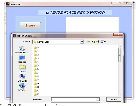
Fig 7.2 shows to select an image for license plate recognition.
Fig 7.2 Image selection.
Fig 7.3 shows Suppose we are clicking the browse without selecting an image then it shows user pressed control
Fig 7.3 Warning Image.
International Journal of Research (IJR)
e-ISSN: 2348-6848, p- ISSN: 2348-795X Volume 2, Issue 10, October 2015Available at http://internationaljournalofresearch.org
Fig 7.4 Browsing Image.
Fig 7.5 gives that Here in this block a segmentation represents the plate number or characters is divided into segments
Fig 7.5 Segmented Image.
Fig 7.6 shows that Recognition is for identifying the number plate
Fig 7.6 Recognition Image.
Fig 7.7 shows that a blur image
Fig 7.7 Blur Image.
Fig 7.8 produces segments for blur image
Fig 7.8 blur image 2
Fig 7.9 shows the clear license plate image
International Journal of Research (IJR)
e-ISSN: 2348-6848, p- ISSN: 2348-795X Volume 2, Issue 10, October 2015Available at http://internationaljournalofresearch.org
Conclusion:
A new and fast algorithm for vertical edge detection was proposed in this project. The performance of this project is faster than the performance of sobel by five to nine times. Here only one license plate is considered for the whole experiments. The rate of correctly detected license plates is 75%. The computation time of CLPD method is 47.7ms is faster than sobel operator which meets the real time requirements.
Here, theATprocesswill be
evaluated first.Then, the accuracy and the computation time of the VEDA are compared with that of the Sobel operator. Finally, the performance of the proposed CLPD method is evaluated. To carry out this evaluation and analysis, The VEDA and the Sobel algorithm are separately used to extract vertical edges. In the first evaluation, the CLPD method has been built
as follows:
ULEA→VEDA→HDD→CRE→PRS→PD. In
the second evaluation, the CLPD methodhas been
built as follows: LEA→Sobel→HDD→CRE→
PRS→PD.
Suppose we met with an accident in that case we are not able to find the person who done an accident . In such cases we recognize a person by using fast method for car-license plate detection. Here this is used for crime prevention. It is also having so many applications.
REFERENCES
[1] G. Adorni, F. Bergenti, and S. Cagnoni , “Vehicle license plate recognition by means of cellular automata,” in Proc. IEEE Int. Conf. Intelligent Vehicles,.
[2] M. H. T. Brugge, J. H. Stevens, J. A. G. Nijhuis, and L. Spaanenburg, “License plate recognition using DTCNNs,” in Proc. 5th IEEE Int.Workshop on Cellular Neural Networks and Their Applications,.
[3] P. Davies, N. Emmott, and N. Ayland, “License plate recognition technology for toll
violation enforcement,” Inst. Elect. Eng. Colloquium Image Analysis for Transport Applications.
[4] H. Bai and C. Liu, “A hybrid license plate extraction method based on edge statistics andmorphology,” in Proc. 17th Int. Conf. Pattern Recognit., Cambridge, U.K.,
[5] M. Fukumi, Y. Takeuchi, H. Fukumoto, Y. Mitsura, and M. Khalid “Neural network based threshold determination for Malaysia license plate character recognition,” in Proc. 9th Int. Conf. Mechatron. Technol.,
[6] E. R. Lee, K. K. Pyeoung, and J. K. Hang, “Automatic recognition of a car license plate using color image processing,” in Proc. IEEE Int. Conf.Image Process., .
[7] S. N. Huda, K. Marzuki, Y. Rubiyah, and O. Khairuddin, “Comparison of feature extractors in license plate recognition,” in Proc. 1st IEEE AMS,Phuket, Thailand.
[8] S. Thanongsak and C. Kosin, “The recognition of car license plate for automatic parking system,” in Proc. 5th Int. Symp. Signal Process. Appl.,Brisbane, QLD, Australia.
[9] F. Martin, O. Martin, M. García, and J. L. Alba, “New methods for automatic reading of VLP’s (Vehicle License Plates),” in Proc. IASTED Int. Conf. Signal Process. Pattern Recognit. Appl., Heraklion.
[10] S.-H. Le, Y.-S. Seok, and E.-J. Lee, “Multi-national integrated car-license plate recognition system using geometrical feature and hybrid pattern vector,” in Proc. Int. Tech. Conf. Circuits Syst. Comput. Commun., Phuket,Thailand.