Interface
Shantanu Telharkar1, Shreerang Dabade2, Tejas Karangale3, Shardul Telharkar4
UG Students, Dept. of Electronics Engineering, KJ Somaiya Autonomous College of Engineering, Vidyavihar,
Mumbai, India1,2&3
UG Student, Dept. of Electronics & Telecommunications Engineering, KJ Somaiya Autonomous College of
Engineering, Vidyavihar, Mumbai, India4
ABSTRACT: This project aims at developing a hardware design to control the motor drivers of a CNC controller. It is described in Verilog entirely and realised on Field Programmable Gate Array (FPGA). While this Motion Control Circuit is highly precise, it can be controlled by the user, using the Serial Peripheral Interface (SPI) protocol. Essentially, any Microcontroller/Microprocessor in the form of a Master can be used to control this Slave Motion Controller Circuit given that the Microcontroller/Microprocessor uses SPI communication protocol.Square wave pulses of varying frequency and number can be faithfully produced for fuelling the motor drivers of the CNC controllers. By aptly manipulating the internal registers of this Controller, desired frequency and number of pulses can be achieved by the user. Moreover, arrangement has also been made to set a direction bit (for the motor) in one of the internal registers of this Controller.Simultaneously, six motors (i.e. axes) can be conveniently controlled using this Motion Controller. The design being completely hardware based, minimal delay is introduced and also precision is optimal.
KEYWORDS:FPGA, Serial Peripheral Interface (SPI), Verilog, Hardware Design, CNC Controller, Motion Control.
I.INTRODUCTION
Need in the industry:
High amount of precision and speed is required to control the motors of the CNC machines, Lathe machines and jewellery cutting machines. We propose an application specific integrated circuit (ASIC) design, realised on FPGA (Field Programmable Gate Arrays) and embedded in a circuit which directly controls the motors of the CNC controller. The user may use any microcontroller/microprocessor which communicates over SPI protocol to control this circuit. This hardware design on FPGA, generates clock signals that are fed to the drivers of the stepper motors to be controlled.
Computer Numerical Control (CNC) Machines:
The technique that involves computers to control machine tools for vivid applications is known as CNC Machining. Each machine follows certain protocol to operate. Once the instructions for the movement of motors are decided by the computer, they are sent to the Motion Controller, which controls the motors using motor drivers. Lathes, mills, drilling machines, laser cutting tools are some of the tools which are conveniently controlled by CNC Machines.
Motion Controller:
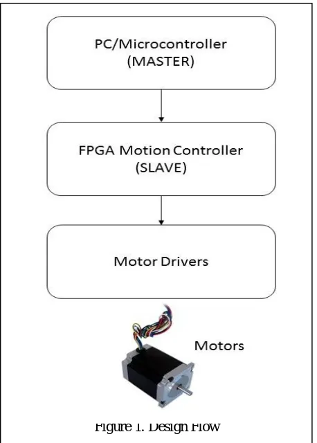
II.FLOW OF CNC CONTROL WITH OUR FPGA DESIGN
Our FPGA based Slave Motion Control Circuit takes inputs from the PC/Microcontroller with SPI Protocol and feeds output pulses to the Motor Drivers. Here, PC = Personal Computer (Host Controller).
III.SCOPE OF THE THESIS
The thesis engulfs a research aimed at optimizing the performance of Motion Controller Integrated Circuits using hardware design. Though it can successfully control 6 axes simultaneously, it would have absolutely no problem controlling 8 axes at a time with minor tweaks in the code. Incorporating the FPGA core in any embedded circuit and loaded with the design proposed in this thesis shall yield an excellent solution.
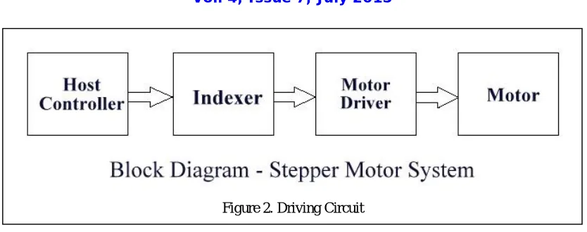
IV.STEPPER MOTOR AND DRIVING CIRCUIT
The typical Stepper motor system is shown in the diagram below, which consists of four components a Host Controller, Indexer, Motor Driver and finally a Stepper motor. In any system these components are present in one form or other. While understanding the motion control interface knowing the function of each block is important. The final block is a Stepper Motor that actually connects to the load. Motor driver consists of phase control logic and power amplifiers that will energize the phases of motor properly. Indexer is the device that will tell motor what to do. Finally, host controller is the machine that will essentially control the whole machine along with stepper motor.
Stepper Motor:
Stepper motor is a brushless motor which divides a full rotation into number of steps. Unlike brushless DC motors which run continuously once supplied with power, stepper motor moves with discrete step angles.
Stepper motor works on the principle of electromagnetism. There is a soft iron shaft surrounded by electromagnetic stator. Both rotor and stator have poles. When the stator is energized the rotor moves to align itself with stator or rotor moves to have minimum gap with the stator. Thus to run a stepper motor the stators are energized in a sequence. Hence we supply pulses to motor driver that will take care of this sequencing. Each pulse supplied to the driver corresponds to one step of stepper motor. Some commonly used terminologies with Stepper Motor are:
a. Step – Angle by which the motor moves.
b. Frequency – Speed of rotation in terms of rotations/pulses per second.
c. Micro stepping – Dividing motors natural full step into smaller increments. The motor micro stepped
at 16x with step angle 0.9° means that now 1 pulse is equivalent to 0.9⁄16 = 0.05625°. Hence motor moves 16 times slower in this case.
d. Torque – Measurement of rotational force.
Calculation of operating frequency:
Consider a 0.9° Stepper motor micro stepped at 64x with a required speed of 1rps. Operating frequency can be easily calculated in this case as,
Pulses/Second = (1 Revolutions)/Second x (400 Pulses)/Revolution x 64 Micro steps = 25600 Pulses/Sec.
Motor Driver:
The Driver converts the indexer command signals into the power necessary to energize the motor windings. In order to run the motor we need pulses and direction signal to determine whether the motor will move forward or reverse. Motor driver receives these signals from Indexer. Motor driver circuit consists of Phase control logic and power amplifier. The phase control logic takes input from Indexer and determines which phase of the motor should be energized. Phases in motor must be energized in a sequence, the phase control logic takes care of this sequencing. The inputs coming from indexer are generally 5V compatible so as to make interfacing with digital ICs easier.
The driver also consists of power supply and power amplifiers. The motor power supply is the supply voltage to power the motor. This voltage level is usually in the 24V DC range but can be much higher. The power amplifiers are used to supply current sufficient to energize the phases in motor.
To make the control accurate by using micro stepping many times micro step drivers are used. These drivers are highly customizable and can be used to micro step at various levels such as 8x, 16x, 64x, 128x and 256x. Also, these type of devices provide facility to limit the output current of the driver.
To adjust the micro stepping and maximum output current number of switches are provided on the micro step driver. Driver must be supplied with 24V DC supply externally. The driver also supports both Bipolar and Unipolar inputs for both Clock pulses and direction inputs.
Indexer (Motion Controller):
Indexer as discussed above tells motor what to do. It generates pulses depending on how many steps are to be taken. Also alters the frequency of output pulses according to the speed requirement of the motor. Indexer receives input from a host controller which determines the speed and extent of motion.
In this thesis we present the design of this part where the Slave (Indexer) receives the input from its master (Host controller) and generates output pulses and direction signals for multiple axes. The design and working of this slave will be explained in following sections.
Host Controller (Computer/Microcontroller):
Host controller is the brain behind the system which determines the course of motion. The host controller can be computer or a PLC or simple user interface. The host controller must communicate with Indexer to feed the information of the motion.
V.MOTION CONTROL INTERFACE
As seen from the previous section, Indexer is vital part of the Stepper motor system. The design of such system on FPGA is the objective of this project.
Serial Peripheral Interface:
The Master (Host controller) sends data to the (indexer). Thus, there must be a common set a rules of communication between a master and slave. There are various protocols available like Serial Peripheral Interface (SPI), I2C, and UART.
We have chosen SPI for the following reasons:
a. Full-Duplex Data transfer.
b. High Speed Data transfer.
c. Easy to Implement.
d. Flexibility – Not limited to 8 bits (Arbitrary choice of message size).
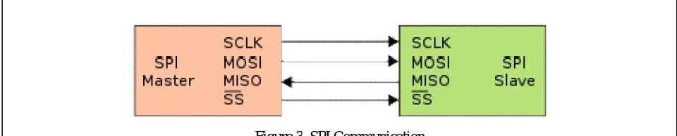
Serial Peripheral Interface is a 4 wire serial communication interface designed for IC controller and chip peripherals to communicate with each other. SPI Bus is full duplex bus and allows data transfer up to 10 MBPS. The SPI communication takes place in Master-Slave architecture where master initiates the frame for reading as well as writing. SPI uses following four signals:
SCLK – Serial Clock (Output from Master). MOSI – Master Out Slave In (Output from Master). MISO – Master In Slave Out (Output from Slave). SS – Active LOW Slave Select (Output from Master).
SPI can be used with a single master and multiple slaves. Each slave will have individual Slave select line.
Data Transfer:
To begin the communication, the master must first configure the clock. Then the master selects the slave by pulling down Slave select line. The data transfer occurs at each SPI clock cycle. The master puts data on MOSI line which is then read by slave and data put on MISO line by slave is read by master. This sequence is maintained even when data is to be transferred only in one direction.The communication generally takes place between two shift registers one from master and one from slave. They are connected in ring type topology. Generally, the data is shifted out in MSB first fashion. Once the registers have exchanged their values, they are filled with new values to continue communication. To indicate end of communication, the master must either stop toggling SCLK line or deselect the slave by pulling SS high. In case of multiple slaves, the ones that are not selected discard the value read on MOSI line.
VI.FPGA SLAVE
In the previous sections we have seen that Host Controller and Indexer (Master-Slave) communicate with each other using SPI protocol. Now, let’s see the concept behind the Motion Control Interface that will generate control signals for multiple motors.
Idea:
The slave generates output pulses according to number of steps to be taken and desired speed. Thus, it must be able to alter the number of pulses and the frequency of output pulses.
To control the motion of motor we need following data: 1. Desired Speed.
2. Extent of Motion. 3. Control Information.
These three factors will be discussed in detail with the block diagram of the design given below. Figure 4. Data Transfer in SPI
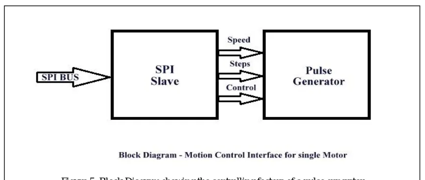
SPI Slave:
SPI slave is a slave designed on FPGA that communicates with Master to receive Desired Speed, Number of Steps and control signals. This module then sends this data to pulse generator where output pulses are generated.
Pulse Generator:
Controlling the output frequency:
Output frequency is an important factor in motion control. To control the output frequency the pulse generator block is supplied with a high-speed clock input. All of the desired frequencies are obtained by dividing this high-speed clock by appropriate number. Thus, for frequency control we need to provide Divisor to pulse generator block. While dividing the clock by desired number we must keep it in mind that the divisor only be integer and thus output frequency will be approximately equal to desired frequency if high-speed clock is not integer multiple of desired clock.
Controlling Number of pulses:
Once we get clock at desired frequency we must limit the number of output pulses. This can be achieved simply by counting the number of pulses and comparing it with desired pulse count. Once pulse count is reached output will be stopped. Thus, this module is simply a counter that operates on clock derived by dividing high-speed internal clock. Other Control:
Motion controller also needs some other controls like Pause/Resume the motion and changing the direction of motor. These controls must be sent to pulse generator.
Finally, the pulse generator will generate output that can be fed to motor driver depending on these inputs which will in turn control the motion of motor.
Example:
Suppose we want to move 1 steps at 50Hz. Assuming internal clock to be 100MHz. Divisor = (100 MHz)/(50 Hz) = 2000000. Count = 1.
Suppose we want to move 3 steps at 100Hz. Assuming internal clock to be 100MHz. Divisor = (100 MHz)/(100 Hz) = 1000000. Count = 3.
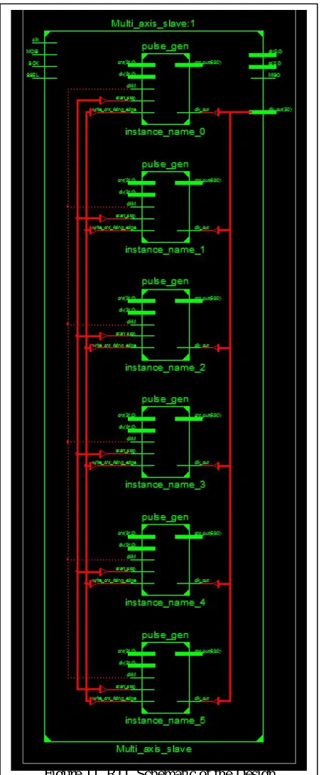
Control of Multiple Motors:
In practical applications, more than one motors are used simultaneously. Simultaneous movement of multiple motors is required in case of 3D printing machines where the position of tool is uniquely determined by 3 co-ordinates. In such cases control for multiple motors (axes) is required. For such cases we can further extend the idea from previous section to make controller for multiple axes. The block diagram for the same is given below:
The block diagram shows a SPI module connected to six pulse generators. Six pulse generators are used to generate signal for 6 different motors (axes). Inputs given to each pulse generator specifies the corresponding Divisor, Count and Control information. Thus, to hold the data for each axis 3 registers are required namely:
1.Divisor – Holds the divisor (to control output frequency).
2. Count – Holds the number of output pulses.
3. Control Word – Holds Control Data such as Pause/Resume and direction.
Need of Command Word:
Now, the data must be loaded into appropriate register of appropriate axis set. To enable proper routing of data one additional information must be transferred that will command the slave as to where to send data. This additional
information is called Command Word. Command word specifies following information:
Axis address – Tells slave which Pulse Generator Should Receive the data.
Axis address Axis Number
000 0
001 1
010 2
011 3
100 4
101 5
Figure 7. Table showing Axis Addresses
Register address – Tells slave which register of chosen pulse generator should load the data.
Register Address Register
00 Control Word
01 Divisor
10 Count
11 NA
Broadcast – Whether or not all of the pulse generators should receive the data.
Read/Write – Whether it’s a read operation or write operation.
The Command Word is 32-bit data that must be sent with each data (Divisor/Count/Control Word). The format of command word is as follow:
31-29 28-27 26 25-2 1 0
Axis Address Register Address Broadcast Reserved Read Write Figure 9. Format of Command Word
Other Registers:
Divisor – 32-bit Divisor (Supporting frequency range of 1Hz – 1MHz). Count – 32-bit Count Value.
Control Word – 32-bit control word.
31-2 1 0
Not Used Direction Run/Stop Figure 10. Format of Control Word
Direction – Sets the direction of the motor.
Run/Stop – If set to 1 then enables the output otherwise disables the output.
VII. RESULTS RTL Schematic (Outer View):
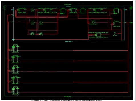
RTL Schematic (Pulse Generator in detail:
Figure 12 sheds light on the Pulse Generator in detail. One can observe the logic which works as described in Figure 6. While the Frequency Divider divides the clock as desired by the user (Master Device), the Pulse Counting logic keeps track of the number of clock pulses that are going out as output clock signal.
Count: 4.
Hence, the frequency of the output waveform = 300MHz/12 = 25MHz. Number of Pulses = 4.
The simulation results were as shown below:
Figure 13. Simulation results
VIII.CONCLUSION
With this design, we get the entire system running internally at 300MHz.This Motion Controller can control 6 axes simultaneously using a single FPGA board.It can attain extreme precision while controlling the motors which is very crucial in applications like Jewellery making machines, Lathe machines etc.It can be implemented for more axes depending on the need of the consumer by just increasing the number of bits in the Command Word Register.
SPI is universally accepted. Hence, this design can be used with almost any microcontroller.
REFERENCES
[1] NurQamarinabintiMohd Noor,AzilahSaparon, “FPGA Implementation of High Speed Serial Peripheral Interface for Motion Controller,” IEEE
Symposium on Industrial Electronics and Applications (ISIEA2012), September 23-26, 2012, Bandung, Indonesia, 2012.
[2] E. Monmasson and M. N. Cirstea, ‘‘FPGA design methodology for
industrial control systems----A review,’’ IEEE Trans. Ind. Electron., vol.
54, no. 4, pp. 1824--1842, Aug. 2007.
[3] Samir Palnitkar, Verilog HDL-A guide to Digital Design and Synthesis (Prentice-Hall, 1966).
[4] M.-W. Naouar, E. Monmasson, and A. A. Naassani, ‘‘FPGA-basedcurrent controllers for AC machine drives----A review,’’ IEEE
Trans.Ind.Electron., vol. 54, no. 4, pp. 1907--1925, Aug. 2007.