ISSN (Print) : 2320 – 3765 ISSN (Online): 2278 – 8875
I
nternational
J
ournal of
A
dvanced
R
esearch in
E
lectrical,
E
lectronics and
I
nstrumentation
E
ngineering
(An ISO 3297: 2007 Certified Organization)
Vol. 4, Issue 7, July 2015
MRAS and Adaptive Observer Techniques for
Speed Estimation in Sensorless Vector
Control Induction Motor Drive
M.AnkaRao1, M.Vijaya Kumar 2, M.Harika3
Assistant Professor, Dept. of EEE, JNTU, Anantapur, Andhra Pradesh, India1
Professor, Dept. of EEE, JNTU, Anantapur, Andhra Pradesh, India2
PG Student [PID], Dept. of EEE, JNTU, Anantapur, Andhra Pradesh, India3
ABSTRACT:Recently, several efforts are made to improve the overall performance of sensorless induction motor drives. Sensorless vector control can be used only for AC motor drives where rotor speed and position sensors are replaced by speed estimators and an observer, which reduces hardware complexity, cost and increases robustness of the drive. In most sensorless control algorithm is based on flux and speed estimation which are obtained from induction motor voltage and current equations [1]. There are many techniques to improve the high dynamic performance of the drive but it remains uncertain at low speed. This paper involves various speed estimation techniques to develop the high dynamic performance at low speed drives without using sensors. It contains the comparison between the Open-loop estimator, MRAS estimator and Adaptive observer by using PI controller of MATLAB/Simulink.
KEYWORDS: Induction motor, Direct vector control, Open-Loop, MRAS, Adaptive Observer.
I.INTRODUCTION
At present induction motor drives dominates the world market by its special features such as simplicity, ruggedness, efficiency, low cost etc., due to this induction motor is also known as “WORK HORSE” of the industry. Induction motor with squirrel cage is the most widely used because of its fixed speed and for lower power drives it is manufactured by die- casting. Sensorless vector control means vector control without rotor speed sensors. In an ideal, sensorless drives provides information about speed and control with an accuracy of 0.5% or better from zero speed to the maximum speed for all operating conditions which are independent of saturation levels and parameters variation. To gain economical control conventional speed sensors are replaced by sensorless speed estimators [5]. In industries an improvedmathematical model is developed to estimate the speed, by which the drives can even work at low or minimum speeds. This technique is used to improve the robust and to reduce the maintenance. The sensorless control algorithm most depends on flux and speed estimation which are obtained from state observer [4].The speed can estimates from the machine terminal voltages and currents by using digital signal processor. The estimation of speed is very difficult because it depends on machine parameters which vary. Although the sensorless vector controlled drives are commercially available now-a-days even it faces the parameters variation problem particularly at minimum speeds and it became a challenge to improve the response of speed estimation. Sensorless vector control uses the dynamic equations of the induction motor to estimate the rotor speed instead of rotational speed sensors. In this paper three sensorless methods are used to reduce the necessity of speed sensors [4].
II.VECTOR CONTROL OF INDUCTION MACHINE
ISSN (Print) : 2320 – 3765 ISSN (Online): 2278 – 8875
I
nternational
J
ournal of
A
dvanced
R
esearch in
E
lectrical,
E
lectronics and
I
nstrumentation
E
ngineering
(An ISO 3297: 2007 Certified Organization)
Vol. 4, Issue 7, July 2015
observed in fig 1. So speed signal is calculated by one of equations to obtain the instant values of current and flux. The speed and torque controlled of vector control is used in AC drives for high dynamic performance applications. The flux is estimated by two methods either by voltage method or current method. Voltage model is better at high speed ranges whereas current model can be used from very low speed range. Vector control can be applied to induction motor drive by using space vector pulse width modulation inverter [2].The pulse width modulation inverter is used to control the output voltages and also optimize the harmonics by performing multiple switching within the inverter with constant DC. The direct vector control Simulink diagram shown below in fig 1.
Stator currents can be converted from q and d-axis to stationary reference frame as
=
sin sin − sin +
cos cos − cos + …… (1)
Fig.1 Direct vector control simulink
Fig.2Current block model
In current block model the rotor flux can be synthesized more easily with the help of speed and current signals, which will be replaced by different techniques like MRAS, open-loop, adaptive observer.
From stator and rotor currents, the torque, flux linkages and field angle is
T = L i i −i i ..….…(2)
φ = L i + L i …… (3)
φ = L i + L i ……. (4)
ISSN (Print) : 2320 – 3765 ISSN (Online): 2278 – 8875
I
nternational
J
ournal of
A
dvanced
R
esearch in
E
lectrical,
E
lectronics and
I
nstrumentation
E
ngineering
(An ISO 3297: 2007 Certified Organization)
Vol. 4, Issue 7, July 2015
tan …….. (6)
III.SPEED ESTIMATION TECHNIQUES 3.1. OPEN LOOP ESTIMATOR:
Various techniques are used in high dynamic performance for estimation of slip, rotor speed and various machine flux linkages. Open loop estimator is one of the technique in which the rotor speed is estimated from voltage equations of induction motor [5]. The accuracy of open loop estimator is greatly depends on machine parameters such as stator resistance , rotor resistance ,rotor self-inductance . At low rotor speed the accuracy is reduced due to
parameters deviation from their actual values which have more influence on the steady state and transient performance of the drive which uses open loop estimator. These parameters vary due to temperature effect and saturation effect [2]. The robustness against parameters mismatch and noise in measured signals can be overcome by using closed loop observers for estimation of speed and flux-linkages can be observed in fig 3.
Fig.3 Open-loop estimator simulink
Rotor speed of open loop estimator is
ω =ω − ω ……. (7)
ω = − − + φ ……. (8)
= u −R i −L …... (9)
= u −R i −L ……(10)
3.2 MODEL REFERENCE ADAPTIVE SYSTEM
ISSN (Print) : 2320 – 3765 ISSN (Online): 2278 – 8875
I
nternational
J
ournal of
A
dvanced
R
esearch in
E
lectrical,
E
lectronics and
I
nstrumentation
E
ngineering
(An ISO 3297: 2007 Certified Organization)
Vol. 4, Issue 7, July 2015
which results in system stability and quick response, where the difference between the reference model and adaptive model are compare into a speed tuning signal( ) which will act as an input to the pi controller, which is used to estimate the rotor output can be observed in fig 4, block model.
Fig.4MRAS based rotor speed observer Reference model equations
= [∫( − ) − ] ….(11)
= [∫( − ) − ] …..(12)
Adaptive model equations
= ∫ − − …..(13)
= ∫ − − ……(14)
3.3ADAPATIVE OBSERVER:
A state observer is a model based state estimator which can be used for estimation of parameters of non-linear dynamic system in real time. In this model the parameters are used from mathematical model, but used parameters are checking continuously by using a feedback correction method. This method will contain actual measured values which will add to the previous values to estimate the output. To obtain full order speed observer stationary reference frame is considered and an error compensator term is added. The following equations are used to build the adaptive observer which can observer in fig 5. The induction machine in terms of state variable in stationary reference frame is
̅
= ̅ +
0 …… (15)
Output vector ̂ = ……(16)
̅= −[1⁄ + (1− )/ ] [ ⁄( )][ ⁄ − ]
ISSN (Print) : 2320 – 3765 ISSN (Online): 2278 – 8875
I
nternational
J
ournal of
A
dvanced
R
esearch in
E
lectrical,
E
lectronics and
I
nstrumentation
E
ngineering
(An ISO 3297: 2007 Certified Organization)
Vol. 4, Issue 7, July 2015
Fig. 5 Adaptive speed observer simulink
The stator current can be estimated by full order adaptive speed observer as
= + + ( − ̂ ) …...(18)
V.RESULT AND DISCUSSION
The three sensorless speed estimation techniques are developed and their related speed responses are observed by using Simulink/ MATLAB.
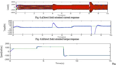
Fig. 6.aDirect field oriented current response
Fig. 6.bDirect field oriented torque response
ISSN (Print) : 2320 – 3765 ISSN (Online): 2278 – 8875
I
nternational
J
ournal of
A
dvanced
R
esearch in
E
lectrical,
E
lectronics and
I
nstrumentation
E
ngineering
(An ISO 3297: 2007 Certified Organization)
Vol. 4, Issue 7, July 2015
The above current, speed and torque waveforms form figs [6.a-6.c] are obtained from direct field oriented conventional method, which speed response will compare with sensorless speed estimation techniques of proposed model inorder to obtain the same response without using speed and position sensors.
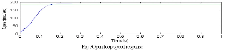
Fig.7Open loop speed response
In open loop estimator the speed response fig 7, contain high ripples which will depends on machine parameters and vary due to temperature effect this can reduce by using MRAS model.
Fig.8MRAS speed response
In model reference adaptive speed estimator the ripples can be reduced when we compare with open-loop estimator as fig 8, to overcome this finally adaptive speed observer technique is chosen.
Fig. 9.aAdaptive speed observer current response
ISSN (Print) : 2320 – 3765 ISSN (Online): 2278 – 8875
I
nternational
J
ournal of
A
dvanced
R
esearch in
E
lectrical,
E
lectronics and
I
nstrumentation
E
ngineering
(An ISO 3297: 2007 Certified Organization)
Vol. 4, Issue 7, July 2015
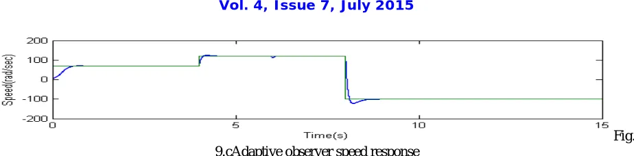
Fig. 9.cAdaptive observer speed response
The speed, current, and torque waveforms of adaptive speed observer can be observed from figs [9.a-9.c] which are similar to conventional direct field oriented techniques. This technique is best among other sensorless speed estimation techniques where the ripples are less compare with others.
Table: Comparison between speed estimation techniques
TECHNIQUES RISE TIME(sec) SETTLING TIME(sec)
Open-Loop Estimator 0.1 0.2
MRAS 0.09 0.18
Adaptive Observer 0.05 0.12
By using the speed response of sensorless speed estimation techniques the comparison is done between rise time and settling time to justify the adaptive speed observer is best among other techniques.
IV.APPENDIX
Nameplate specifications used in induction machine Magnetizing Inductance Lm 0.0403 mH Rotor Resistance Rr 0.25Ω Rotor leakage Inductance Llr 0.0412mH Rotor Resistance Rs 0.3Ω Stator Leakage Inductance Lls 0.0415mH
Rated frequency f 50HZ
Rated speed N 200rpm
V.CONCLUSION
In this paper, direct field oriented control and sensorless vector control for induction motor is dealt. Various speed estimation techniques are used to improve the accuracy of the drive. Adaptive speed observer is the best speed estimation technique which is used from low speed range. Compare to other techniques the adaptive speed observer as less rise time and settling time. The speed estimation techniques mainly depends on machine parameters which varies due to temperature effect, skin effect and saturation levels this can be reduced by using self-commissioning or by online tuning.
REFERENCES
[1] T. Raghu, J. SrinivasRao, and S. Chandra Sekhar, “Simulation of Sensorless Speed Control of Induction Motor Using APFO Technique”,International Journal of Computer and Electrical Engineering, Vol. 4, No. 4, August 2012.
[2] P. Vas, Sensorless vector and direct torque control. New York: Oxford University Press, 1998. [3] BimalK.Bose, Modern Power Electronics and AC Drives handbook: The University of Tennessee, 2002.