Western University Western University
Scholarship@Western
Scholarship@Western
Electronic Thesis and Dissertation Repository
9-5-2013 12:00 AM
Collaborative Policy-Based Autonomic Management in IaaS
Collaborative Policy-Based Autonomic Management in IaaS
Clouds
Clouds
Omid Mola
The University of Western Ontario
Supervisor Dr. Mike Bauer
The University of Western Ontario Graduate Program in Computer Science
A thesis submitted in partial fulfillment of the requirements for the degree in Doctor of Philosophy
© Omid Mola 2013
Follow this and additional works at: https://ir.lib.uwo.ca/etd
Part of the Computer and Systems Architecture Commons, Other Computer Engineering Commons,
Other Computer Sciences Commons, Software Engineering Commons, Systems Architecture Commons, and the Theory and Algorithms Commons
Recommended Citation Recommended Citation
Mola, Omid, "Collaborative Policy-Based Autonomic Management in IaaS Clouds" (2013). Electronic Thesis and Dissertation Repository. 1595.
https://ir.lib.uwo.ca/etd/1595
This Dissertation/Thesis is brought to you for free and open access by Scholarship@Western. It has been accepted for inclusion in Electronic Thesis and Dissertation Repository by an authorized administrator of
COLLABORATIVE POLICY-BASED AUTONOMIC MANAGEMENT IN IAAS CLOUDS
(Thesis format: Monograph)
by
Omid Mola
Graduate Program in Computer Science
A thesis submitted in partial fulfillment of the requirements for the degree of
Doctor of Philosophy
The School of Graduate and Postdoctoral Studies The University of Western Ontario
London, Ontario, Canada
c
Abstract
With the increasing number of “machines” (either virtual or phys-ical) in a computing environment, it is becoming harder to monitor and manage these resources. Relying on human administrators, even with tools, is expensive and the growing complexity makes manage-ment even harder. The alternative is to look for automated ap-proaches that can monitor and manage computing resources in real time with no human intervention. One of the approaches to this problem is policy-based autonomic management. However, in large systems having one single autonomic manager to manage everything is almost impossible. Therefore, multiple autonomic managers will be needed and these will need to cooperate in the overall manage-ment. We propose a management model using multiple autonomic managers organized in a hierarchical fashion to monitor and man-age the resources in a computing environment based on provided policies. We develop a communication protocol to facilitate collabo-ration between different autonomic managers, define the core opera-tions of these managers and introduce algorithms to deal with their deployment and operation. We also introduce an approach for the inference of the communication messages from policies and develop several algorithms for joining and maintaining the management hi-erarchy. We propose a deployment system that can discover relevant resources in a computing environment automatically to facilitate the deployment of autonomic managers at different levels of a physical system. We then test our approach by implementing it in a small private Infrastructure-as-a-Service (IaaS) cloud and show how this collaboration of autonomic managers in a hierarchical way can help to adopt to high stress situations automatically and reduce the SLA
violation rate without adding any new resources to the environment.
Keywords: Cloud Computing, Autonomic Management, Policy-Based Management, Collaborative Management.
Dedication
This dissertation is lovingly dedicated to:
My lovely father, who encouraged me to continue my studies, helped me migrate to Canada and taught me to never give up.
My beautiful mother, who prayed for me every day, missed me but hid her tears and believed in me more than what I deserved.
The love of my life, Zeinab, who left her job so I can continue my studies, stood by my side through difficult times and sup-ported me in this life journey.
My little son, Mahan, who should know that it is always possi-ble to learn and gain knowledge, even when you have a baby at home!
Acknowledgements
A big special thanks to the best supervisor I have ever had. Without his patience, mentorship and support this work was not possible. I wish I could thank him enough for being my supervisor. Thank you Dr. Mike Bauer, now and always.
I would like to acknowledge and thank Dr. Hanan Lutfiyya, my supervisory committee member, who were always more than gener-ous with her expertise and time and helped me with her constructive feedbacks to improve this work.
I wish to thank Dr. Mark Daley, my supervisory committee mem-ber, Dr. Miriam Capretz, Dr. Mike Katchabaw and Dr. Patrick Martin for being in the examining board. I appreciate your time, insights and valuable comments.
I am very grateful to the Computer Science department staff mem-bers, Ms. Cheryl McGrath, Ms. Janice Wiersma, Ms. Dianne Mc-Fadzean and Ms. Angie Muir who always helped me specially when I was teaching courses at Western. Thanks for making this experience wonderful.
I would like to thank all of my friends in our research group (DiGS) and Sharcnet administrators specially Mr. Nathaniel Sherry, who devoted their time to discuss and brainstorm different ideas re-lated to this thesis. Your constructive criticisms contributed in im-proving this work.
Last but not least, thanks to all of my family members specially my lovely smart brother, Amir, who was always kind, passionate and keen about me. I love you all and feel blessed to have you around me.
Contents
Abstract ii
Dedication iv
Acknowledgements v
List of Tables xi
List of Figures xii
List of Algorithms xiii List of Appendices xiv
1 Introduction 1
1.1 Motivation . . . 1
1.2 Towards Autonomic Cloud Management . . . 4
1.3 Contributions . . . 5
1.4 Roadmap . . . 7
2 Related work 9 2.1 Multiple Managers . . . 9
2.2 Coordination of Managers . . . 12
2.3 Policy-Based Interactions . . . 16
2.4 Cloud Management . . . 17
2.5 Summary . . . 20
3 Scope and Challenges 22
3.1 Autonomic Management . . . 23
3.1.1 Policy-Based Management . . . 25
3.2 Cloud Architecture . . . 27
3.3 Challenges . . . 30
4 Approach and Model 34 4.1 Assumptions . . . 35
4.2 Hierarchical Model . . . 36
4.3 Defining Elements of the Model . . . 42
4.3.1 Managed System . . . 42
4.3.2 Events . . . 46
4.3.3 Policies . . . 47
4.3.4 Structural Relationship of Autonomic Managers 50 4.4 Summary . . . 51
5 Autonomic Manager Behaviour 53 5.1 Naming Scheme . . . 53
5.2 Communication Protocol . . . 58
5.3 Start-up . . . 61
5.4 Processing . . . 65
5.5 Termination Detection . . . 68
5.6 Inferring Messages From Policies . . . 70
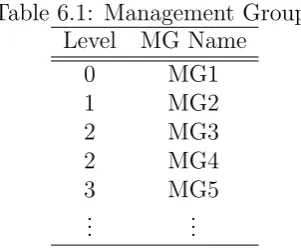
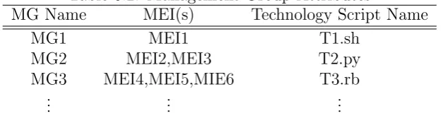
6 Autonomic Manager Deployment 77 6.1 Management Groups . . . 79
6.2 Management Group Attributes . . . 80
6.3 Management Group Members . . . 83
6.4 Discovery Algorithm . . . 85
6.5 Deployment Algorithms . . . 90
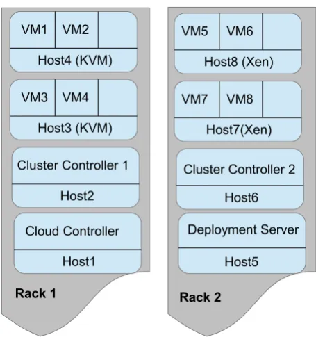
6.6 Deployment in IaaS Clouds . . . 93
6.6.1 Sample IaaS Layout . . . 94
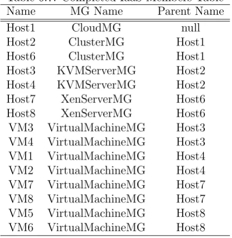
6.6.2 Deployment Tables . . . 95
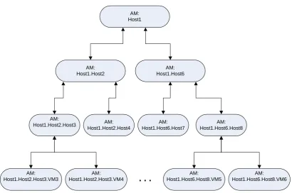
6.6.3 Deployed Managers . . . 98
7 Experiments and Evaluation 101 7.1 Evaluation: Performance Study . . . 102
7.1.1 Experimental Setup . . . 102
7.1.2 Policies . . . 106
7.1.3 Scenario 1: No Collaboration . . . 109
7.1.4 Scenario 2: One Level Collaboration . . . 111
7.1.5 Scenario 3: Two Level Collaboration . . . 113
7.1.6 Discussion . . . 116
7.2 Case Study: High Frequency Trading . . . 117
7.2.1 Management Architecture . . . 119
7.2.2 Implementation . . . 121
7.2.3 Policies . . . 125
7.2.4 Lessons Learned . . . 127
7.3 Summary and Discussion . . . 128
8 Conclusion 131 8.1 Summary . . . 131
8.2 Main Contributions . . . 133
8.3 Future Work . . . 135
Bibliography 137
Appendix A Managed Element Infos 146 Appendix B Technology Scripts 159
Curriculum Vitae 161
List of Tables
6.1 Management Groups . . . 80
6.2 Management Group Attributes . . . 83
6.3 Management Groups Members . . . 83
6.4 IaaS Cloud Management Groups . . . 96
6.5 IaaS Cloud MGAttributes . . . 97
6.6 Initial Iaas Members Table . . . 98
6.7 Completed IaaS Members Table . . . 99
6.8 Deployed AM Names . . . 100
7.1 Experiment’s Management Groups . . . 105
7.2 Experiment’s MGAttributes . . . 105
7.3 Results of three scenarios . . . 117
7.4 CTS Management Groups . . . 121
7.5 CTS MGAttributes . . . 121
List of Figures
3.1 Autonomic Manager Architecture (from [33]) . . . 24 3.2 Eucalyptus Hierarchical Architecture (from [34]) . . . . 29 4.1 AMs hierarchy based on the cloud architecture . . . . 37 4.2 IaaS Cloud Structure . . . 39 5.1 AMs hierarchy based on the cloud architecture . . . . 74 6.1 IaaS Cloud Layout . . . 95 6.2 AMs hierarchy after deployment on IaaS cloud . . . 100 7.1 Experiments Cloud Physical layout . . . 103 7.2 Hierarchy of managers based on physical layout . . . . 104 7.3 Apache response time with no manager collaborations 110 7.4 Apache response time with one level of collaboration . 112 7.5 Apache response time with two levels of collaboration . 114 7.6 Managers hierarchy after migration of VM2 to Server 2 115 7.7 Case Study Physical Layout . . . 120 7.8 Management’s Hierarchy - two levels . . . 121 7.9 Data flow for a host machine agent . . . 124
List of Algorithms
5.1 AM Startup . . . 62
5.2 Monitoring Loop . . . 66
5.3 Management Interval Loop . . . 66
5.4 Policy Evaluation . . . 67
5.5 AM Termination Detection and Removal . . . 69
5.6 ExecuteActions . . . 72
6.1 Member Discovery . . . 87
6.2 Members Addition: Autonomic Manager Deployment 91 6.3 Members Removal . . . 92
List of Appendices
Appendix A Managed Element Infos . . . 146 Appendix B Technology Scripts . . . 159
Chapter 1
Introduction
In recent years, there has been a lot of research into “Autonomic Computing” [17], especially about how to build autonomic elements and managers [19]. Autonomic managers (AMs) try to monitor and manage resources in real time to ensure that the components they manage are self-configuring, self-optimizing, self-healing and self-protecting (so called “self-*” properties [36]).
1.1
Motivation
The basic idea behind a self-management system is inspired from the autonomous nervous system of human body [39]. The need for hav-ing such systems is becomhav-ing more obvious as the number of com-puting machines (such as virtual or physical) is increasing. Data centers are becoming larger and more complex, particularly those focused on providing cloud services. The challenges of monitoring and managing these cloud computing environments in order to meet users’ expectations of highly available and responsive systems are increasingly more difficult. Therefore, as the number of cloud users
2 Chapter 1. Introduction
are growing, having self-managed systems seems to be inevitable in the future management of the computing infrastructures.
In the broader vision of autonomic computing, large complex data centers and systems will consist of numerous autonomic managers handling systems, applications and collections of services [20]. Some of the systems and applications will come bundled with their own autonomic managers, designed to ensure the self-properties of par-ticular components. Other managers will be part of the general man-agement of the computing environment. Therefore, the complexity of managing a large system will entail a number of different auto-nomic managers which must cooperate in order to achieve the overall objectives set for the computing environment and its constituents. However, the relationships between these managers and how they cooperate introduce new challenges that need to be addressed.
1.1. Motivation 3
managers start and others end in response to changes in the system? In order to ensure that service level agreements are met and that we use the infrastructure more efficiently, we have focused on the following problems:
• How to deploy autonomic managers dynamically in a scalable manner?
• How autonomic managers should collaborate with each other in a large computing environment to achieve global goals?
• How to automate the configuration of autonomic managers and the communication process itself, to minimize the administra-tive costs of managers’ setup and maintenance?
• What should happen when a new autonomic manager gets added or when an already running one stops working? How system re-act to these changes dynamically?
We consider the use of policy-based managers [6] in addressing these problems. The ultimate goal is to automatically monitor and manage a large system by a collective of collaborating local auto-nomic managers. In such an environment, we assume that each local autonomic manager has its own set of policies and is trying to optimize the behaviour of the elements that it manages by respond-ing to the changes in the behaviour of those elements. We assume some managers will also be expected to monitor multiple systems and directly or indirectly to monitor other local AMs.
4 Chapter 1. Introduction
the autonomic managers are organized into a hierarchy and inves-tigate how they can communicate at different levels of a hierarchy based on the active policies. Although there are other approaches to communications between managers, such as peer-to-peer, multi agent, etc. we have chosen a hierarchical approach since a) it is a good starting point and has advantages over flat structures and it is important to understand how it can be effectively utilized or where there may be limitations and b) it has a natural alignment with an IaaS cloud architecture - our particular system focus.
The core issues addressed are how these local managers should communicate with each other, how they should be deployed auto-matically across the computing environment and what information they have to exchange to achieve global performance goals. We will also focus on how to automate the collaboration process itself by inferring the communication messages from the active policies in a particular autonomic manager. In a hierarchical organization of au-tonomic managers, policies are used at different levels to help man-agers decide when and how to communicate with each other as well as using polices to provide operational requirements. We assume that one of the roles of a higher level manager is to aid other au-tonomic managers when their own actions are insufficient to meet operational requirements.
1.2
Towards Autonomic Cloud Management
1.3. Contributions 5
on virtualization technology where client applications can run on separate operating virtual machines (VMs). Such environments can consist of many different host machines each of which might run multiple VMs. As the number of hosts, virtual machines and client applications grow, management of the environment becomes much more complicated. The cloud provider must worry about ensuring that client service level agreements (SLA) are met, must be con-cerned about minimizing the hosts involved, and minimizing power consumption.
As part of this thesis, we focus on how our management model and approach can be applied to such environments (e.g. IaaS clouds) and implement these ideas in a small cloud. We also explain the ap-plication of our approach to a real world problem where we worked with a private company to evaluate these ideas in a high frequency trading cloud environment and tuned the general strategy based on practical experiences.
1.3
Contributions
The main contributions of this work and the novel ideas are as fol-lows:
• There has been generally a little work in the area of multi-ple autonomic managers and how to handle dynamic changes. Therefore, this work is to somewhat unique in this area.
6 Chapter 1. Introduction
as nodes. Our hierarchical approach in this thesis encompasses a focus on local and intermediate managers as well as including global cluster level managers which makes it unique in address-ing this problem.
• The design of a hierarchical autonomic management model for large computing environments with formal definition of different elements in that model (Chapter 4).
• The design of a communication protocol between autonomic managers that facilitates their collaboration in achieving global goals (Section 5.2). Some of these communication messages can be inferred from policies and therefore can help with automating the collaboration between managers.
• Introduction of multiple algorithms that define the behaviour of a specific autonomic manager and its relationship with other managers in that management model. These algorithms include the start-up, processing, termination detection and communi-cation message inference from policies (Chapter 5).
• Design of a deployment system based on the management model proposed to automate the deployment of different autonomic managers across the computing environment with minimum ad-ministrative efforts (Chapter 6).
1.4. Roadmap 7
complexity of members addition algorithm is O(log(n)) and the members removal is O(n) in the worst case.
We also evaluated these ideas in two different experimental set-tings. In one case, we implemented this approach in a small private cloud and measured the potential advantages of a hierarchical ap-proach. We also implemented some of our ideas and algorithms in a real world setting involving a high frequency trading cloud infras-tructure.
1.4
Roadmap
8 Chapter 1. Introduction
Chapter 2
Related work
There has been wide range of research dealing with the issues in-volving multiple autonomic managers for managing large systems. In this Chapter, we review some of the key works in this area and discuss the similarities and differences with our work. We focus in particular on previous work that looks at having multiple managers and examine how the interactions or collaboration are addressed. We also discuss some of the previous research that involves policy-based management with multiple autonomic managers, cloud management and general approaches towards coordination of multi-agent systems.
2.1
Multiple Managers
Some researchers have already begun to study how collaboration among local autonomic managers can be done in order to achieve a global goal. A hierarchical communication model for autonomic managers has also been used by some researchers. In this section, we describe some of the relevant research in this area and explain the differences with our work.
10 Chapter 2. Related work
Famaey, et al. [14] used a policy-based hierarchical model for network management. They showed how this model can be mapped to the physical infrastructure of an organization and how this hier-archy can dynamically change by splitting and/or combining nodes to preserve scalability. They also introduced the notion of “context” that needs to be accessible in the hierarchy. The “context” is the information that is made available from a child to its father. Their work focused on the network layer and studied the transmissions be-tween autonomic elements by looking at the number of bytes trans-mitted during communication. In this work, “context” is basically the monitoring information that can be retrieved from standard pro-tocols such as the Simple Network Management Protocol (SNMP). The limitation of these protocols is that they only provide network management information at the macro levels and they do not deal with detailed organized information that is required for manage-ment at higher levels. It is also difficult to perform request/response type of communication due to protocol constraints. We have also adopted the hierarchical approach used in this work, but we develop a new protocol to exchange communication messages between auto-nomic managers. We also use a mechanism to infer communication messages from policies automatically and show when and how this communication should happen.
2.1. Multiple Managers 11
12 Chapter 2. Related work
2.2
Coordination of Managers
Mukherjee, et al. [32] used coordination of three managers work-ing on three different parts of a system (Power Management, Job Management, Cooling Management) in a flat structure to prevent a data center from going to a critical state. The critical state is when there is a possibility of the ambient temperature to reach the redline temperatures. They showed how the three managers can cooperate with each other to keep the data center temperature within a cer-tain limit that is suitable for serving the current workload and at the same time not using more power than required. They showed how these three managers can be configured to work based on different business policies. Their approach used three different strategies to combine the three management tiers and preconfigured the system to work based on these three strategies. The three management tiers are fixed and adding new managers to this system will be challenging both in terms of collaboration and scalability, particularly because the coordination between management tiers depends on their con-figuration and can not change dynamically.
2.2. Coordination of Managers 13
not fixed and can be changed based on the active policies. The poli-cies themselves can also change on the fly based on new demands rising from time to time.
14 Chapter 2. Related work
policy distribution and how policies are derived from higher level objectives is not the focus of our work. If we assume the SON coor-dinator as a higher level manager then this system can be considered as part of the hierarchical system proposed in our work.
pro-2.2. Coordination of Managers 15
vide algorithms to handle these cases.
Multi-agent approaches toward autonomic manager collaboration have been explored by some researchers. In these systems, each autonomic manager is represented as an agent and multi-agent com-munication techniques are used for their interactions. We explain some of the most relevant ones to our work.
The “Unity” architecture [50] uses performance utility functions that need to be calculated by each agent with the result being sent to a central coordinator (“Arbiter”) for computing the globally op-timal resource allocation. The same kind of approach is used in [12] by having a coordinating agent that tries to coordinate power and performance agents. This approach could be used as part of the hi-erarchical approach that will be presented in this thesis, but it does not seem to be scalable to a larger system just by itself, because adding a new agent to this system will introduce challenges in agent interactions and configurations. This can be considered as a special case of the hierarchical approach proposed later in the thesis, but with only one level of hierarchy.
16 Chapter 2. Related work
other agents in the system. The agents do not request information on demand. This approach can lead to a major overhead in large sys-tems and turn into a bottleneck itself. In our model, each manager does not need to have information about all other managers mostly because of the layered hierarchical architecture. It is also possible to get updated information on demand if it is needed.
2.3
Policy-Based Interactions
Salehi and Tahvildari [41] published a survey article on self-adaptive systems and the main research challenges. They proposed [40] a policy-based orchestration approach for resource allocation to dif-ferent autonomic elements. They suggested the use of a global or-chestrator to coordinate the resource provisioning at a global level between multiple autonomic elements. They used crisp action poli-cies for non-competitive states where there is no conflict on resource requests and fuzzy utility policies to resolve conflicts in competitive states. In this work, the interactions between autonomic managers and the orchestrator is limited to resource requests, the managers are fixed and the communications are tightly coupled. This system can be considered as one level of hierarchy that will be explained in this thesis. However, we developed a new communications protocol which includes different types of messages and considered the dy-namic joining and leaving of managers from the system.
2.4. Cloud Management 17
with a “Mission” that needs to be accomplished during an interac-tion. This mission is based on predefined customized interfaces for each role. This approach is similar to interactions in ad-hoc net-works and SMCs need to discover each other and try to accomplish missions based on their defined role in the system. There are cer-tain policies for each role which facilitate the interactions. In our work, we deal with a hierarchy of managers and therefore each man-ager needs to communicate with either its children or its parent and there is no need to define “role” for each manager to make the in-teractions possible. Although, this SMC role based approach might also be applicable in a hierarchical fashion, the overhead in defining unnecessary interfaces introduces a challenge. Another major differ-ence is that we try to infer communication messages from policies dynamically to the extent that is possible but in the SMC system all interactions have to be specified beforehand through missions.
2.4
Cloud Management
18 Chapter 2. Related work
could monitor the changes inside a virtual machine. In the applica-tion of our model to a cloud environment, it is possible to have at least one autonomic manager inside virtual machines which can join and leave the management hierarchy dynamically. Another differ-ence is that they use a polling mechanism with multiple time-scales to do the monitoring at different levels. For example, they monitor virtual machines in seconds, the “pods” in minutes and the “pod sets” in hours or days. In our work, we proposed the use of notifi-cation messages for communinotifi-cation between managers and therefore managers can communicate based on demand rather than polling which reduces the overall overhead. We also focus on policies and how they affect the relationship between managers in a dynamic structure where multiple autonomic managers can join and leave the management system, but the number of controllers in their system is limited to three with hard-wired connections between them which limits the scalability of their approach.
2.4. Cloud Management 19
total demands are more than available resources at the node level. The global controller (GC) monitors all nodes in the cloud and uses a statistical machine learning technique to rearrange virtual machines among nodes. These migrations help to optimize virtual machine placements and meet the SLOs. Basically they use different models at each level to estimate the demands and adjust the environment and as a result it is more complex to change the model dynami-cally. In our work, we use the same Monitor-Analyse-Plan-Execute (MAPE) loop/model at all levels of the hierarchy but policies can change on the fly. In their work, the interactions between controllers are tightly coupled. For example, the VMC sends resource requests to NC and the NC responds to that request by using a resource actuator to change the VM parameters. This also shows the tightly-coupled relationship between controllers and can become an issue for scalability of the approach when the number of virtual machines and nodes increase. In our work, we develop algorithms to handle dynamic joining and departure of managers to the hierarchy and the message based communication protocol is loosely-coupled.
20 Chapter 2. Related work
required information from the virtual machines and made decisions based on that information. This approach is limited in terms of scalability and single point of failure. In our management model, we consider multiple autonomic managers deployed at different levels of the system. We consider dynamic joining and leaving of these man-agers so that the system can still operate if one or some of them are terminated. We also focus on a range of managed elements in the data center, such as applications, virtual machines, physical servers and so on but in these works the main focus is only on virtual ma-chines. Overall, the algorithms developed in these works can be used as part of our management model and inside some of the managers that are responsible for managing virtual machines. These could be embedded in to the policy sets defined for those managers.
2.5
Summary
We explored some of the work most relevant to this thesis and dis-cussed some of their limitations and constraints. We also explained how our work is different from each. In general, understanding of the collaboration between policy-based autonomic managers is still a relatively new area of research with a lot of research challenges yet to be answered. It is still a work in progress in the autonomic computing area; some areas where the previous work has not yet studied include:
communica-2.5. Summary 21
tion.
2. An organizational model that can handle the dynamic joining and leaving of managers and adapt to the changes in the infras-tructure.
3. Methods that address scalability concerns as the number of el-ements increase in the computing environment and automation of communication between managers to the extent that is pos-sible.
4. Means of deploying multiple managers to the right position and keep them up to date and running with the least human admin-istrative efforts.
Chapter 3
Scope and Challenges
In this Chapter, we cover some of the background information for our work before describing our approach in more detail. This Chap-ter is meant to give readers a clear view of the scope and challenges addressed in this thesis.
We first explain the basic concepts of autonomic management and associated techniques used in this thesis. We then describe the IaaS (Infrastructure-as-a-Service) cloud architecture since it is the envi-ronment we focus on to explore our approach and test our ideas. This Chapter also provides some of the background behind why we have initially chosen to focus on the hierarchical structure for orga-nization of autonomic managers. Moreover, the cloud architecture will be used in the evaluation of our approach and discussed fur-ther in the description of our experiments. We also discuss the main questions we have addressed in this thesis.
3.1. Autonomic Management 23
3.1
Autonomic Management
Autonomic Management has been a very active field of research in the past decade [20, 36, 17] and a variety of research challenges have been raised in this area [19]. It is used for service level guarantees [28], aggregated information monitoring [26, 25] and many other applications [27]. However, the main idea behind autonomic man-agement is to build systems that are self-configuring, self-healing, self-optimizing and self-protecting and it is inspired from the human body’s Autonomous Nervous System (ANS) [39].
The ANS gives our bodies the ability to adapt to dynamic changes in the environment around us automatically by sensing these changes, deciding what actions the body should take and enforcing those ac-tions. Similarly, an autonomic manager which is responsible for mon-itoring and management of one or more elements of a computing system (i.e. Managed Elements - MEs) should be able to sense the changes in those elements, decide what actions need to be taken and enforce those actions, to adapt the whole system automatically.
24 Chapter 3. Scope and Challenges
called Monitor-Analyze-Plan-Execute (MAPE) loop.
There are various ways a manager can choose the best actions, but we use policy-based management in this thesis. Policy-based agement assumes that the knowledge base in the autonomic man-ager includes defined policies and therefore it can look into those provided policies to pick the appropriate actions that need to be enforced. Policy-based management is explained in more detail in section 3.1.1. The autonomic manager combined with one or more managed elements is called Autonomic Element (AE). Therefore, in order to be able to manage an AE itself, the AE can provide sen-sors and effectors to the outside world. This will help forming multi layers of autonomic management in a system.
Figure 3.1: Autonomic Manager Architecture (from [33])
3.1. Autonomic Management 25
different management intervals. That is, one manager can run its MAPE loop every 100 millisecond whereas another manager can run the loop every 10 minutes. This is useful for enforcing management at different levels of the hierarchy while trying to minimize over-head. At the lowest levels, monitoring is required more often as the changes are very dynamic and happen more frequently, while man-agers at higher levels need less frequent monitoring and therefore can in principle operate at higher management intervals. This will result in less traffic and processing overhead in the management system.
3.1.1 Policy-Based Management
Policy-based management is a well-known technique in the auto-nomic management area. An overview of policy-based management along with relevant standards and implementation techniques can be found in [3, 6]. Many languages have been developed to express policies however only some of them support Event-Condition-Action paradigm [16]. Ponder [11] is one of the most famous policy lan-guages that supports this paradigm.
26 Chapter 3. Scope and Challenges
In this work, we use policies expressed as event, condition, action (ECA) policies. In general, all of our policies are of the form:
OnEvent: E
if Set of Conditions then
Set of ordered actions
end if
Upon raising an event inside the autonomic manager, then any policy which matches the event will get evaluated. If the conditions in the policy are met, then the policy actions get triggered. We pro-vide examples of policies in the following sections.
At AM start-up there are configuration policies that set up the autonomic manager environment, identify the appropriate managed elements and configure them. It is however possible to automatically perform policy mapping [35] at start-up time and configure elements based on other types of policies. A sample configuration policy ex-plicitly defined in the policy set of an autonomic manager would look like:
OnEvent: VMConfigurationEvent
if true then
VirtualMachineMEI.setRefreshInterval(4000ms)
end if
3.2. Cloud Architecture 27
checking the CPU utilization, then the intent of this policy is that the AM will check the utilization every 4000 milliseconds and exe-cute policies after each refresh.
These policies represent how the management system should react to dynamic changes in the environment and might change from time to time based on a strategy-tree approach [46, 47] or administrative needs. However, the focus of our work is not on how the policies get distributed between different managers (though for completeness we describe an approach in our work), we assume that multiple auto-nomic managers can retrieve their policy sets from a repository and that these policies can change over time if required.
3.2
Cloud Architecture
The focus of this thesis is on autonomic management and commu-nication among multiple autonomic managers. However, while the focus is on autonomic management, we want to explore our ideas in an environment that has some structure. Given the importance of cloud computing environments, we choose to focus on this environ-ment and, more specifically, we choose IaaS clouds to test our ideas.
28 Chapter 3. Scope and Challenges
different customers with different service level requirements (via Ser-vice Level Agreement (SLA) parameters).
To have a better understanding of a cloud provider environment and architecture, we take a closer look at Eucalyptus [34] (an open source software for building private and hybrid clouds). There are three main distinct components that form the Eucalyptus architec-ture in a hierarchical fashion and each of the components have a different role in the system. These separate components can be physically located on one single machine to form a cloud or can be distributed over several machines. An overview of the Eucalyptus architectural model is illustrated in Figure 3.2.
The main three components of the Eucalyptus architecture are briefly described below:
• Cloud Controller (CLC): The CLC is the top level component for interacting with users and getting the requests. It handles all incoming requests and performs high level resource scheduling and system accounting. The CLC makes the top level choices for allocating new instances of virtual machines, authentication, reporting and quote management. Only one CLC can exist in each cloud.
3.2. Cloud Architecture 29
Figure 3.2: Eucalyptus Hierarchical Architecture (from [34])
virtual network overlay, and gather/report information about a set of nodes.
30 Chapter 3. Scope and Challenges
This architecture shows a hierarchical relationship between dif-ferent components of a typical IaaS cloud. A deeper look at the cloud architecture and the management needs suggest that provid-ing management capabilities in real time through a sprovid-ingle centralized manager is almost impossible, because of the hierarchical layers in the architecture with different responsibilities at each layer. Also, the dynamics of load changes and the need to react to these changes in real time with increasing number of virtual machines and physi-cal nodes makes it much more difficult to achieve these goals with a traditional centralized manager.
We adopt the same hierarchical approach towards the autonomic management of this infrastructure. We organize policy-based auto-nomic managers in a hierarchical fashion which corresponds roughly to the underlying infrastructure components. Hence, the overall management of the system is then possible by having a set of collabo-rating autonomic managers organized in this hierarchy. At the same time, each manager in the hierarchy acts autonomously to manage part of the cloud on its own, based on given policies.
3.3
Challenges
3.3. Challenges 31
problem of server/VM consolidation [9, 22, 54]. However, the main challenges in monitoring and managing the cloud environment occur after the virtual machines are placed and start working and receiving loads. After a virtual machine is placed with some specific service level agreements and starts working, the clients can connect to it for servicing. The number of clients and their interactions with the ap-plications on the virtual machine will vary and create a dynamically changing workload. There may be times that the traffic is too high and the virtual machine gets overloaded or there may be some other times that the traffic is too low so that the virtual machine is un-derutilized. In the first case, SLA violations might occur whereas in the second case the energy and allocated resources might be wasted. One of the approaches to this problem is dynamic consolidation of VMs which usually is a heuristic based approach and does not allow explicit specification of QoS metrics [5].
In the context of an IaaS cloud, these problems are compounded with multiple virtual machines, multiple different applications and different service requirements. There are also many related man-agement challenges that need to be addressed [56], including, how to initially configure and deploy autonomic managers, how multiple managers located at different parts of the system should communi-cate, etc. In this thesis, we focus on the following problems:
ma-32 Chapter 3. Scope and Challenges
chine (or an application inside it) according to the agreed SLA while minimizing the resource usage. We should also know if there is any way to get help from another manager while one manager has reached its local limits (e.g. communication and collaboration).
• How can we achieve autonomic elasticity in the cloud? Auto-nomic elasticity happens when a virtual machine can grow and use more resources if needed, and shrink back again and re-lease resources if there is no demand for them. The answer to this problem would show what autonomic managers are needed, where they should be deployed and what kind of policies are re-quired on each one.
• How to automate the collaboration of managers in the system? In order to deal with a dynamic environment where applications can start and stop and where virtual machines may come an go, there is a need to ensure that managers can communicate and collaborate. However, the interaction between managers must be dynamic too. How can communication between managers be defined in a changing environment as managers come and go? How is the communication structured and what informa-tion is exchanged (e.g. communicainforma-tion protocol). We look at a means of inferring the communication messages needed between different autonomic managers from their active policies.
3.3. Challenges 33
the managers will change dynamically as applications and vir-tual machines come and go. What is a good strategy for de-ploying these managers so that it requires minimal manual ad-ministrative efforts?
• How can autonomic managers detect the addition or removal of different elements and automatically restructure their orga-nization (e.g. hierarchy) without human intervention? In a real cloud, applications, virtual machines and physical nodes can join or leave the system at any time and thus their related autonomic managers can also join or leave the management sys-tem at any time. So, how does the organization of managers (e.g. hierarchy) restructure on the fly to reflect these changes?
• How to automate the manager configuration and minimize the administrative costs to setup autonomic managers? Each auto-nomic manager needs to be configured before or upon start-up. However, in a large system configuring all managers one by one can become a challenging and error prone job for administra-tors. How can this process be automated to help administrators and reduce the costs associated with it?
Chapter 4
Approach and Model
In this Chapter, we explain our approach and assumptions towards autonomic management of a large system (e.g. IaaS cloud) with a particular focus on the challenges outlined in Section 3.3. We propose a hierarchical model and provide definitions of different el-ements in this model.
Based on the previous discussions, we propose to use a number of different autonomic managers at different parts of the system. By doing this, the problem of managing a large system entails a num-ber of autonomic managers where each one is dealing with smaller or more localized elements. Then each manager’s job is to focus on managing that element (or small set of elements) efficiently based on certain policies. For example, an autonomic manager for an Apache web server should only focus on the behaviour of the web server itself and not the performance of the machine that this server is running on or, the autonomic manager for a Node Controller (NC) should only focus on the performance and behaviour of that specific node.
4.1. Assumptions 35
4.1
Assumptions
In this Section we describe the general assumptions we have for a management system that consists of multiple autonomic managers working collaboratively to achieve certain goals.
We assume that inside each autonomic manager there is an event handling mechanism for processing and generating events and no-tifying the interested parties inside that manager. For example, there could be an event bus and different components within the autonomic manager (AM) subscribe to certain events and upon rais-ing any of those events, the subscriber would get notified. This event handling mechanism is useful for handling event-condition-action policies and also for communication between managers.
36 Chapter 4. Approach and Model
shows the usage of this policy engine.
We assume that there is a central registry and that each AM will contact this registry during its start-up process. This registry will be used by each manager to find the contact information (e.g. ID in Definition 6) of its parent in the management hierarchy and is used to facilitate the process of adding new managers to the system dynamically.
In order to remove the single point of failure for registry and pol-icy repository and also to increase the availability of the system, one can have backups (e.g. registry, repository) running at the same time which can be replaced upon a failure. This is beyond the cur-rent focus of this thesis.
We also assume that each manager should provide an interface for receiving messages from other managers. This interface should be able to receive different message types, parse them and do the proper actions according to the specification of that message. The message format and types are explained in more detail in Section 5.2.
4.2
Hierarchical Model
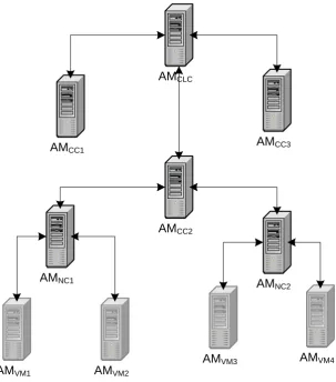
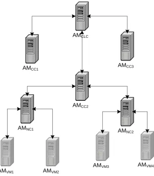
4.2. Hierarchical Model 37
AMCLC
AMCC2
AMNC1 AMNC2
AMCC3 AMCC1
AMVM1 AMVM2
AMVM4 AMVM3
38 Chapter 4. Approach and Model
We choose the hierarchical approach because it is straightforward and a good starting point to explore collaboration between auto-nomic managers. A hierarchy provides a simple, yet useful, struc-ture and has several advantages over a flat strucstruc-ture (e.g. improved scalability by reducing communication overhead that only happens between parent and child). This hierarchical model is also in natu-ral alignment with the architecture of a typical Infrastructure-as-a-Service (IaaS) cloud which is our particular system focus.
The physical structure of a typical IaaS cloud would look like Fig-ure 4.2. In this layout, every host machine is shared among multiple virtual machines and there could be many applications running in-side each virtual machine. The host machines are grouped together to form a cluster and a combination of these clusters will form the cloud.
4.2. Hierarchical Model 39 VM3 VM1 VM2 Host1 VM9 VM7 VM8 Host3 VM6 VM4 VM5 Host2 Cluster1 . . . VM12 VM10 VM11 Host4 VM18 VM16 VM17 Host6 VM15 VM13 VM14 Host5 Cluster2 . . . . . .
IaaS Cloud 1
Figure 4.2: IaaS Cloud Structure
40 Chapter 4. Approach and Model
Then the AMs at the cluster controller (CC) level are responsible for monitoring a cluster with all physical nodes inside it. These AMs have a global view of the whole cluster and know which nodes are overloaded with traffic and which nodes are underutilized. In case of a virtual machine migration, these AMs can decide where should be the destination of the candidate VM for migration and inform the appropriate child AM to perform the migration to the selected destination.
Similarly, the AM at cloud controller (CLC) level monitors and manages all of the clusters. The overall monitoring of the whole cloud can happen at this level. This AM is the main entry point for defining business policies for the cloud. In case one cluster is overloaded and there is an underutilized cluster, this AM can choose that cluster and ask the overloaded child (Autonomic Manager) to offset some of the load to the underutilized cluster by migrating a few virtual machines to that cluster.
This is a logical organization of autonomic managers and does not necessarily reflect the physical allocation of the AMs, i.e., they do not necessarily need to be located on different physical machines. In a large cloud they could be located on separate machines or some may be located on the same machines. These AMs should then collec-tively work together to ensure that policies are met, e.g. policies for optimizing performance, minimizing resource usage, avoiding SLA violations, etc.
4.2. Hierarchical Model 41
more complex tasks should be divided into smaller tasks and deliv-ered to different responsible managers at lower levels. For example, the AM at the Cloud Controller (CLC) level should take care of bal-ancing the load between different clusters and the AM at the Cluster Controller (CC) level should look after balancing the load between different nodes inside that cluster. Similarly, the AM at the node level should optimize the resource usage of that physical machine among different VMs and while the autonomic manager inside a VM should work on optimizing the applications performance. Assuming that the management “tasks” are specified in terms of policies, this means that we need policies with different granularity deployed at different levels of the infrastructure and we need to ensure that AMs can communicate properly with each other to enforce those policies.
These autonomic managers can be added or removed from this hi-erarchy based on demands of the computing infrastructure. There-fore, any particular hierarchy of AMs is not fixed and can change over time depending on what managers get created or removed dy-namically. Automatic deployment and removal of AMs is a very im-portant feature in order to minimize the impact of the management system on overall system performance and so that administrators do not have to worry about the hierarchy configuration every time there is a change in the infrastructure. The management system should be able to adapt to the infrastructure changes and automatically re-configure itself as changes happen. We will explain this process in more detail in Chapters 5 and 6.
42 Chapter 4. Approach and Model
assumed, by the administrators directly or by some other process. A good “rule of thumb”, however, would be to define similar sets of policies for autonomic managers that manage the same kinds of entities, e.g. the AMs that manage virtual machines would have similar policies, those that manage physical nodes would have sim-ilar policies. The rationale for this is that managers of the same kind of entity will have many similar or identical policies, e.g. a set of policies for managers of virtual machines might make use of the same policy to handle the situation when a VM has insufficient computing resources to meet an SLA. This way, sets of policies can then be stored in the policy repository and be retrieved upon AM start-up based on the kind of entity that the AM is managing.
4.3
Defining Elements of the Model
In this Section, we define various elements of our model. These def-initions help to make concepts clear and we also use them in our algorithms and operations introduced in subsequent chapters.
4.3.1 Managed System
4.3. Defining Elements of the Model 43
We assume the supported characteristics and operations of each ME is defined in a ManagedElementInfo, which is used to define the policies. For example, the AM responsible for managing a virtual machine, could be provided information in a
VirtualMachineMan-agedElementInfo, which would include all supported metrics and
ac-tions of a general virtual machine. This is like a class definition for a specific ME which is used by the manager for policy definition. An instantiation of this class can then be used to evaluate the policies.
Definition 1 A ManagedElementInfo, MEI, is a tuple MEI=hM, Ai, where:
• M is a finite set of metrics, M={M1, ..., Ml}, where:
∀Mi ∈ M, Mi = hNi, Tii | Ni = Identif ier(M etricN ame), Ti =
M etricT ype ∈ {String, int, double, ...}
• A is a finite set of possible actions, A={A1, ..., Am}.
We denote the finite set of MEI by MEISet={M EI1, ..., M EIn}
Actions are supported operations that can be done on that man-aged element. For example, actions for a VirtualMachineMEI could
be Shutdown, StartService, etc. The metrics associated with a MEI
include both attributes like VirtualMachineName which is a string, and metrics such as CPUUtilization and MemoryUtilization which are floating point numbers (e.g. type double).
44 Chapter 4. Approach and Model
XENVirtualMachineMEI can both inherit actions and
metrics/prop-erties of a VirtualMachineMEI like virtual machine name, CPU uti-lization, etc.
Once an MEI is defined, it can be instantiated several times based on the need - an instantiation is referred to as a
ManagedElementO-bject, defined below. For example, after a change in CPUUtilization
or upon receipt of an event a VirtualMachineMEI can get instan-tiated with the latest facts/values and be passed to the policies for evaluation. This is done as part of the “Monitor” phase in MAPE loop (see Section 3.1). Basically, in order to monitor (gather infor-mation through sensors) a specific managed element the AM can instantiate its MEI and update the metrics that are available for that element.
Definition 2 Given a set MEISet, a ManagedElementObject (MEO)
is a tuple hm, ai where there is a MEI=hM, Ai ∈ MEISet such that
• a=A,
• m = {hN1, V1, T1i, ...,hNl, Vl, Tli} | M = {hN1, T1i, ...,hNl, Tli}
and Vi is the value of a metric.
We denote the set of managed objects by MEOSet={M EO1, ..., M EOn, ...}
A MEO is an instance of a MEI and represents actual values of a managed element information in the system. The metrics in an
MEO are those in the definition of the class and the Vi are values
associated with those metrics. Each Vi would typically be a value
4.3. Defining Elements of the Model 45
These MEOi are used for policy evaluation from time to time.
The metrics and actions defined inside a ManagedElementInfocan be used in defining policies. For example, a VirtualMachineMEI can have a “CPUUtilization” metric and a “StopService(serviceName)” action both defined in its MEI. CPUUtilization represents the CPU utilization of the virtual machine which gets updated from time to time and StopService action takes a service name and stop that ser-vice from running. Therefore, an example policy to manage virtual machine stress can be:
OnEvent: ManagementInterval
if VirtualMachineMEI.CPUUtilization > 85 then
VirtualMachineMEI.StopService(“XY”);
end if
This policy get executed at each management interval (e.g. upon raising ManagementInterval event), and checks the CPUUtilization
of the virtual machine and if it is above 85%, it stops a service called “XY”. Other possible ManagedElementInfos are: ApacheMEI,
Host-MachineMEI, ClusterMEI, etc.
Therefore at the time of policy definition, administrators use an
MEI (e.g. one can think of it as a “class”) to define policies but at run time the instantiated MEI (e.g. MEO) is passed to the policy engine to evaluate the policy’s condition and perform actions. It is the job of the policy engine to match the MEO values with the right
46 Chapter 4. Approach and Model
happens inside the manager and Algorithm 5.4 described in Chapter 5 defines this policy evaluation process.
4.3.2 Events
We assume that inside each autonomic manager there is an event handling mechanism for generating events and notifying the inter-ested parties (such as policy evaluator) inside the AM. For example, there could be an event bus and different subscribers to certain events and upon raising those events any subscribers will get notified. This event handling mechanism is useful for handling event, condition, action policies and also for communication between managers. We assume that for a given system and MEIs, that there are a finite number of event types.
Definition 3 Given a set MEISet, an event type, Et, is a pairhN, Mi
where:
• N is the name of the event type,
• M={m1, ..., mo}, and mi is the name of a metric from an MEI
∈ MEISet.
We denote the finite set of event types by ET ={Et1, ..., Etz}.
Definition 4 Given a set ET, an event E is a pair hn, mi where
there is an event type Et = hN, Mi ∈ ET and
• n is the name of the event n = N,
• m ={hm1, v1i, ...,hmo, voi}, where M ={m1, ..., mo}, and vi is
4.3. Defining Elements of the Model 47
We denote the set of events by EventsSet ={E1, ..., Ep, ...}.
For a given set of event types, there may be an infinite number of possible events, depending on the values associated with the metrics of that event type. In this respect, an event is an instantiation of an event type with the associated metrics assigned values.
One sample event is ManagementInterval event, which is a simple event with no metrics that gets triggered on a time interval to trigger management loop.
E1 = hM anagementInterval, nulli
Another sample event is HelpRequest event, which can have one or more metrics attached to it. In this example, CPUUtilization of a virtual machine is attached to this event.
E2=hHelpRequest,{hV irtualM achineM EI.CP U U tilization,95i}i
4.3.3 Policies
All of the policies are expressed as event, condition, action (ECA) policies. In general, all of our policies are of the form:
PolicyName: N
OnEvent: E
if Set of Conditions then
Ordered Set of Actions
48 Chapter 4. Approach and Model
Upon raising an event inside the autonomic manager, then any policy which matches the event will get evaluated. If the conditions in the policy are met, then the policy actions get triggered. We pro-vide examples of policies in the following sections.
Definition 5 Given a set MEISet and a set of events types ET, then
a policy is a tuple hN, E, C, Ai where N is the policy name, E ∈ ET
is one of the event types, C is a finite conjunction of conditions, and
A is an ordered set of actions defined in MEI ∈ MEISet. Therefore,
Pl=hN, E, C, Ai, where:
• E ∈ ET,
• C={C1, ...Cp} and Ci=hM N ame, Operator, Ti or “true”, where
MName is the metric name, Operator is a relational operator
and T is a constant indicating a threshold value,
• A={A1, ..., Aq}, ∀Ai ∈ A, ∃ MEIj ∈ M EISet | Ai = M EIj.Ak
We denote the set of policies by PL={P l1, ..., P lr}.
4.3. Defining Elements of the Model 49
P l1 = { “ApacheResponseTimePolicy”,
ManagementInterval,
{ApacheMEI.ResponseTime > 500},
{ApacheMEI.IncreaseMaxClients(25)} }
In this policy, ManagementInterval is an event that gets triggered in a certain time interval (e.g. every 1500ms) and it has no metrics associated with it. ApacheMEI is the managed element information for Apache and ResponseTime is one of the metrics defined in it.
IncreaseMaxClients is one of the actions defined in ApacheMEI and
will increase the MaxClient property of the Apache web server by a certain number (in this case 25).
At AM start-up there are configuration policies that set up the AM environment. A sample configuration policy would look like:
P l2 = { “StartUpConfPolicy”,
Configuration,
{true},
{VirtualMachineMEI.RefreshInterval=5000} }
This policy happens on autonomic manager start-up (once the
Configuration event is raised) and configures the refresh interval of
50 Chapter 4. Approach and Model
4.3.4 Structural Relationship of Autonomic Managers
In order to explain the relationship between autonomic managers, we first need to define the AM itself.
Definition 6 Given a set MEISubSet ⊂ MEISet, a set of event type
ETSubSet ⊂ET and a set of policies PLSubSet ⊂ PL, an Autonomic
Manager(AM) is a tuple
hID, N ame, M EISubSet, ET SubSet, P LSubSet, M I, RIi where ID
is the AM’s unique identifier which other AMs can use for
commu-nication purposes, Name is the AM name, MI is the management
interval which determines the time interval for triggering the
man-agement loop and RI is the refresh interval which determines the time
interval to refresh metrics of the managed elements in MEISubSet.
We denote the set of AMs by AMSet={AM1, ..., AMt}
The autonomic manager ID is a globally unique identifier among all AMs and can be changed from time to time. This can be a URL or a physical IP and port where the AM can be accessed. The autonomic manager Name is a string and is set as a configuration parameter. This name is mapped to the AM ID and will be stored in the registry to be used to dynamically discover AMs for connection purposes. As part of the start-up process (Algorithm 5.1) each AM should register its name and ID in the registry.
4.4. Summary 51
Definition 7 Given an AMSet, a Hierarchy H of AMs is a tuple
hAM Set, Edgesi where AMSet is the set of autonomic managers as
the nodes of the tree and Edges={(AMi, AMj)|AMi, AMj ∈ AM Set}
is the set of edges connecting two AMs to each other. The following
properties exist in this hierarchy:
• ∃ AM ∈ AMS | @ AMi ∈ AMS, (AMi, AM)
• if (AMi, AMj) ∈ Edges ⇒ @ AMk | (AMk,AMj) ∈ Edges
• if (AMi, AMj) ∈ Edges ⇒ (AMj,AMi) ∈/ Edges
This definition means that there is at least one root manager in the hierarchy and for each AM there is only one parent. Also if a manager is the parent of another AM, then it cannot be that AM’s child (e.g. there are no loops).
4.4
Summary
52 Chapter 4. Approach and Model
any time and therefore it is important to have mechanisms in place to detect these dynamic changes and the impact they have on the management hierarchy.
Chapter 5
Autonomic Manager Behaviour
This Chapter describes the general algorithms that each autonomic manager has to follow individually to make the communication and collaboration between managers in the hierarchy possible. We ex-plain general behaviour of an autonomic manager and describe dif-ferent algorithms that run inside it. These algorithms specify the process of an AM start-up, how policy evaluation is done and how termination detection is handled in the hierarchy. We also explain how to infer certain kinds of communication messages from policies.
By having a collective of autonomic managers each following these algorithms, it will be possible to build a hierarchical management system and preserve it while dynamic changes happen in the system (e.g. AMs start or stop working).
5.1
Naming Scheme
Each autonomic manager should have a name that can be resolved to an ID at runtime. The name and ID for each AM is explained in Definition 6. Separating name from ID, which is basically the
54 Chapter 5. Autonomic Manager Behaviour
main access point for each AM, helps autonomic managers to dy-namically register themselves in the registry and also to search for, identify and contact their parent manager in the hierarchy. An AM
ID might change over time (e.g. as result of an IP change on system restart) but that manager will still be accessible after it updates its new ID in the registry (e.g. as part of the start-up process).
An AM name is dynamically provided to it as a configuration parameter by the deployment system explained in Chapter 6 and theoretically can be anything, however we propose a naming scheme in which this name includes the parent name of the manager. In other words, instead of having two configuration parameters (one for AM name and one for its parent name) we embed the parent name as part of the AM name itself. This approach is based on the assumption that each AM must be given its parent name as well to be able to look it up in the registry and start the communication process, because in the hierarchical system each manager is only able to communicate with either its children or its parent. Therefore, in this proposed naming scheme an AM name is acceptable as long as an autonomic manager can extract its parent name from it. In this section, as part of the proposed naming scheme we suggest a process of naming different AMs at different levels of the hierarchy which includes the parent name as part of it.
5.1. Naming Scheme 55
in the registry. Therefore we use a hierarchical naming convention to name AMs too. An AM name will be the name of its parent in the hierarchy plus the location and managed element name separated by a symbol (e.g. dot in this case).
AM Name = Parent Name“.”(Location[“-”Managed Element Name])
The location is a physical or virtual machine name that this AM is running on and the managed element name is either the name of the entity this AM is managing or is null. Therefore, the name of the root manager responsible for the whole cloud can be “host1-cloud” or simply “host1” and for a manager responsible for the first cluster of that cloud can be “host1-cloud.host2-cluster1” or if it is running on the same machine as the cloud AM it can be “host1-cloud.host1-cluster1”. Similarly for the manager of a physical node in the first cluster can be “host1-cloud.host2-cluster1.host3”, the managed ele-ment name is not added to the location in this name (e.g. it is null). This naming scheme helps the deployment system to automatically deploy autonomic managers to the right place and the process of dy-namically creating this name is explained in Algorithm 6.2 of Chap-ter 6. Moreover, administrators have the ability to decide and choose the structure of the managed element name and when it should be null (through technology scripts explained in Section 6.2) based on their administrative needs and their computing environment.
ma-56 Chapter 5. Autonomic Manager Behaviour
chines. For example, the name of an AM managing Apache inside vm1 will be “host1-cloud.host2-cluster1.host3.vm1.vm1-apache”. In this way, it is possible to have another AM for managing Apache on a different virtual machine with no naming conflict since the name of that manager will be “host1-cloud.host2-cluster1.host3.vm2.vm2-apache”. By having a name like this, each manager has straightfor-ward access to the name of its parent (e.g. a prefix of its own name) and it can easily use that for communication. For example, the AM with name cloud.host2-cluster1.host3.vm1” can use “host1-cloud.host2-cluster1.host3” to contact its parent in the hierarchy by looking up its ID in the registry.
Another challenge will be how this name can be set as a configu-ration parameter in an autonomic manager in a dynamic way. This happens as part of the deployment process (see Chapter 6) but the basic idea is that, at the time of deploying a new manager, one of the required steps is to configure this name based on the level on which that manager is being deployed; this is particularly relevant in IaaS. For example, when a virtual machine is being placed into a physical server, its manager should be configured with the right name which includes both the physical and virtual machine names. This process happens dynamically as part of the deployment system (see Algorithm 6.2).
5.1. Naming Scheme 57
deployed on them do not change frequently. One exception to this are virtual machines. It is possible to migrate virtual machines from one node to another either as result of a policy or manually by an administrator. If a virtual machine migrates from one node to an-other the manager responsible for that virtual machine and all its children should change their names to reflect this migration to a new host (e.g. a new parent in the new host is now responsible for these managers). This migration will be detected by the deployment system automatically (see Algorithm 6.1 in Chapter 6) and as a re-sult, all AMs on the migrated virtual machines get redeployed with their new names. As part of this redeployment, AMs restart and go through the start-up process explained in Algorithm 5.1 which will result in registering the new names. The old names get invalidated in the registry by the old parent after missing to receive a response from the migrated child. This process is explained later as part of the termination detection algorithm (Algorithm 5.5).
![Figure 3.1: Autonomic Manager Architecture (from [33])](https://thumb-us.123doks.com/thumbv2/123dok_us/7792551.1291707/39.595.150.460.409.632/figure-autonomic-manager-architecture-from.webp)
![Figure 3.2: Eucalyptus Hierarchical Architecture (from [34])](https://thumb-us.123doks.com/thumbv2/123dok_us/7792551.1291707/44.595.137.491.111.405/figure-eucalyptus-hierarchical-architecture-from.webp)