Scholarship@Western
Scholarship@Western
Electronic Thesis and Dissertation Repository
5-12-2014 12:00 AM
Use of Microsoft Kinect in a dual camera setup for action
Use of Microsoft Kinect in a dual camera setup for action
recognition applications
recognition applications
Omar Ghassan Kayal
The University of Western Ontario
Supervisor
Jagath Samarabandu
The University of Western Ontario
Graduate Program in Electrical and Computer Engineering
A thesis submitted in partial fulfillment of the requirements for the degree in Master of Engineering Science
© Omar Ghassan Kayal 2014
Follow this and additional works at: https://ir.lib.uwo.ca/etd
Part of the Other Computer Engineering Commons
Recommended Citation Recommended Citation
Kayal, Omar Ghassan, "Use of Microsoft Kinect in a dual camera setup for action recognition applications" (2014). Electronic Thesis and Dissertation Repository. 2072.
https://ir.lib.uwo.ca/etd/2072
This Dissertation/Thesis is brought to you for free and open access by Scholarship@Western. It has been accepted for inclusion in Electronic Thesis and Dissertation Repository by an authorized administrator of
USE OF MICROSOFT KINECT IN A DUAL CAMERA SETUP FOR
ACTION RECOGNITION APPLICATIONS
(Thesis format: Monograph)
by
Omar Kayal
Graduate Program in Electrical and Computer Engineering
A thesis submitted in partial fulfillment
of the requirements for the degree of
Masters of Engineering Science
The School of Graduate and Postdoctoral Studies
The University of Western Ontario
London, Ontario, Canada
c
Conventional human action recognition methods use a single light camera to extract all the necessary information needed to perform the recognition. However, the use of a single light camera poses limitations which can not be addressed without a hardware change. In this the-sis, we propose a novel approach to the multi camera setup. Our approach utilizes the skeletal pose estimation capabilities of the Microsoft Kinect camera, and uses this estimated pose on the image of the non-depth camera. The approach aims at improving performance of image analysis of multiple camera, which would not be as easy in a typical multiple camera setup. The depth information sharing between the camera is in the form of pose projection, which depends on location awareness between them, where the locations can be found using chess-board pattern calibration techniques. Due to the limitations of pattern calibration, we propose a novel calibration refinement approach to increase the detection distance, and simplify the long calibration process. The two tests performed demonstrate that the pose projection process performs with good accuracy with a successful calibration and good Kinect pose estimation, however not so with a failed one. Three tests were performed to determine the calibration per-formance. Distance calculations were prone to error with a mean accuracy of 96% under 60cm difference, and dropping drastically beyond that, and a stable orientation calculation with mean accuracy of 97%. Last test also proves that our new refinement approach improves the outcome of the projection significantly with a failed pattern calibration, and allows for almost double the camera difference detection of about 120cm. While the orientation mean calculation accuracy achieved similar results to pattern calibration, the distance was less so at around 92%, however, it did maintain a stable standard deviation, while the pattern calibration increased as distance increased.
Acknowledgements
I would like to start by thanking my supervisor Dr. Jagath Samarabandu for giving me the privilege to work with him on his research starting in 2012. I am grateful for his valuable mentor-ship, advice, motivation, and financial support during my program. I am appreciative of the vast knowledge he shared with me, his time that he so generously offered, and his dedication to help me reach my goals with the completion of my Masters degree. With his guidance, I have expanded my research capabilities, gained priceless knowledge, and improved professionally. I have enjoyed my time, time which will be missed. Thank you Dr. Samarabandu.
I would also like to thank my parents, Ghassan and Rouba, and siblings, Rayan and Baraa for their great support, and for believing in me throughout the tough years. I could not have done it without you.
I would also like to thank Dr. Abdelkader Ouda for his guidance and great mentor-ship during my Teaching Assistance work. You have helped me greatly, and overlooked my short-comings, which I sincerely appreciate.
I would like to thank my colleague Ali for his help on countless occasions relating my research work, course work, and Teaching Assistance work. You have helped my greatly, and I will not forget that. I would also like to thank my colleague Akila for directing me on my research work, and his willingness to always help. You are a great photographer by the way. I would also like to thank my colleague Dwayne for involving me with his research study, it was a great experience. Lastly, I would like to thank my colleague Raymond, for his support, and for his amazing demonstration of meteorite rocks and Mars talk. Good luck with your research. You guys are awesome, and I thank you all.
Lastly, I would like to thank my great friends Ahmad Turk, Amin El-Nagger, Bandar Ald-hafeeri, Feras Obeid, Hassan Ouda, Nader Hallak, Saqib Dadabhoy and Thabet Marwa for their support, and being there for me throughout my Masters experience. It would have been a lot harder without you guys. Thank you.
Contents
Certificate of Examination ii
Abstract ii
List of Figures x
List of Tables xiii
List of Appendices xiii
1 Introduction 1
1.1 Background . . . 1
1.2 Motivation . . . 3
1.3 Problem statement . . . 3
1.4 Summary of contribution . . . 4
1.5 Outline . . . 5
2 Literature review 6 2.1 Brief introduction to the Action Recognition model . . . 7
2.2 Low Level: Core technology . . . 10
2.2.1 Object segmentation . . . 10
Static camera . . . 11
Moving camera . . . 13
2.3 Mid level: Human Activity Recognition Systems . . . 17
2.4 High level: Applications . . . 18
2.5 Motivation for the proposed approach . . . 18
2.5.1 Single camera feature extraction and action recognition . . . 18
2.5.2 Stereo camera setup . . . 20
2.5.3 Multi view camera setup . . . 20
2.6 Microsoft Kinect . . . 21
2.7 Mutli view Kinect setup . . . 22
2.8 Calibration . . . 23
2.8.1 Brief overview . . . 23
2.8.2 Single camera Calibration . . . 25
3 Method Architecture and Justification 27 3.1 Setup overview . . . 28
3.1.1 Brief Introduction . . . 28
3.1.2 Design . . . 29
3.2 Stereo-calibration . . . 34
3.3 Pose estimation . . . 36
3.3.1 Depth extraction . . . 36
3.3.2 Skeletal extraction . . . 37
3.3.3 Skeletal Projection . . . 38
3.4 Calibration refinement . . . 40
3.4.1 Overview . . . 40
3.4.2 Angle correction . . . 41
3.4.3 Distance correction . . . 42
3.4.4 Center Point extraction . . . 44
4 Testing and results 54
4.1 Stereo Calibration . . . 54
4.1.1 Test 1: Pattern recognition . . . 55
Test 1 results and discussion . . . 56
4.1.2 Test 2: Measurement accuracy vs pattern count . . . 58
Results: . . . 58
4.1.3 Test 3: Measurement Accuracy vs distance and angle between the cam-eras . . . 60
Maximum Distance (Test 3a) . . . 61
Maximum Angle (Test 3b) . . . 61
Results: . . . 61
4.1.4 Discussion of test results . . . 64
4.2 Pose estimation and projection . . . 66
4.2.1 Test 4: Kinect Pose estimation . . . 66
Results: . . . 67
4.2.2 Test 5: Pose projection . . . 69
Results: . . . 69
4.3 Calibration refinement . . . 71
4.3.1 Test 6: Calibration refinement . . . 72
Maximum Distance (Test 6a) . . . 72
Maximum Angle (Test 6b) . . . 72
Results: . . . 73
5 Conclusion and future work 77 5.1 Summary . . . 77
5.2 Future work . . . 78
5.2.1 Improved tracking . . . 78
A Kinect camera 87
B 3D to 2D Projection 89
B.1 Orthographic Projection . . . 89 B.2 Perspective projection . . . 91
Curriculum Vitae 93
List of Figures
1.1 Examples of different use of recognition. a)Blob tracking, a form that de-tects the entire body and represents it as a box, useful in tracking players in a playing field b)Body controller, a very recent addition to the game industry, uses the tracking of body parts as the controller to enhance the gaming expe-rience c)Medical applications, useful in physiotherapy and health monitoring
d)Another example of blob tracking, Surveillance . . . 2
2.1 Object segmentation [15] . . . 9
2.2 Features extraction categories [15] . . . 9
2.3 Action recognition algorithms [15] . . . 10
2.4 Action recognition System [15] . . . 11
2.5 Background subtraction . . . 13
2.6 Pose estimation Examples [15] . . . 15
2.7 Action learning and classification [15] . . . 17
2.8 Distance Space [4] . . . 19
2.9 Pin hole camera . . . 23
2.10 Pin hole camera Model (Exclusing the skew) . . . 24
2.11 . . . 26
3.1 3 dimensional Euler angles . . . 29
3.2 Kinect axis directions and Euler angle orientation. TheY axis is towards the top of the camera, theXaxis is to the left, and theZaxis is in the Kinect camera lens direction . . . 30
triangle signifies the Kinect’s view area, and the darker signifies the standard
camera’s view area. Both triangles intersect in the view overlap section . . . 31
3.4 Skeleton model [20] . . . 32
3.5 Process breakdown . . . 33
3.6 Stereo Calibration step, the two pictures were taken at the same time . . . 34
3.7 Shotton el al [25] depth image and ground truth body parts . . . 37
3.8 Kinect and camera in world axis. The figure shows the equivalent depth value of Kinect with respect to the other camera’s local axis. The Kinect is capable of depth values up to 3.5m, however, the other camera is not restricted with this value . . . 38
3.9 Finding the angle in the calibration correction step . . . 42
3.10 Finding the distance difference between the two cameras . . . 43
3.11 3D to 2D projection . . . 44
3.12 Silhouettes and edges . . . 45
3.13 Silhouettes and edges . . . 46
3.14 Process outline . . . 48
3.15 Main 1class . . . 49
3.16 kinectCam and cameraclass . . . 49
3.17 skeletalProjectionclass . . . 50
3.18 calibCameraandstereoCalibclasses . . . 50
3.19 recalibrationclass . . . 51
3.20 CreateButtonLayoutclass . . . 52
3.21 UML class diagram . . . 53
4.1 Distance consistency performance . . . 56
4.2 Angle consistency performance . . . 57
4.4 Angle performance . . . 59
4.5 Percentage Accuracy . . . 60
4.6 Test3 Results . . . 62
4.7 Camera distance positioning . . . 63
4.8 Camera Angle limitation example . . . 64
4.9 Chessboard patterns . . . 66
4.10 Kinect Results . . . 67
4.11 Dual camera skeletal projection part 1 . . . 70
4.12 Dual camera skeletal projection part 2 . . . 70
4.13 Dual camera skeletal projection part 3 . . . 71
4.14 Dual camera skeletal projection part 4 . . . 71
4.15 Test 6a Results . . . 74
4.16 Test 6b Results . . . 75
5.1 Ayazoglu’s el al.’s [1] method in action. As can be seen from the image, the trajectory of the car tracked by one camera is mapped by the other camera with the occluded view . . . 79
5.2 a) Articulated human body model b) Position of the 5 coplanar points during Mid stance [16] . . . 80
5.3 a) First camera b) Second camera [5] . . . 81
A.1 Kinect camera specs [19] . . . 87
A.2 Infrared Dot pattern . . . 88
B.1 Orthographic projection view1 . . . 90
B.2 Orthographic projection result2 . . . 90
B.3 Orthographic projection view3 . . . 92
B.4 Orthographic projection view4 . . . 92
Appendix A Kinect camera . . . 87 Appendix B 3D to 2D Projection . . . 89
Chapter 1
Introduction
1.1
Background
With technology integration into our lives becoming more and more defined and established than ever before, it is becoming crucial to find better ways to communicate with technology. This exchange comes in different forms ranging from well defined mouse and keyboard inputs, to more complex audio, video, and image input. However, advancement in computing has made it possible to process large volumes of data in a short amount of time, giving rise to better machine recognition of the less defined data.
Computer vision has been a hot topic for many years, due its huge potential and application base, and with the advancement in computing power, its now more possible than ever before. Computer vision is used in surveillance, gaming, sport tracking, health care monitoring and much more as shown in figure 1.1. However, designing a system that will work in a specific application is a challenging task, and has to be carefully designed to be capable of handling unexpected changes.
Human action recognition in computer vision is becoming increasingly in high demand, and the need for a reliable, marker-less systems has never been so critical. However, developing a method that can cope with a broad range of actions, especially in complex scenarios, is still a
challenge. Recent advances in computer vision and pattern recognition had made it possible to recognize more complex action, making for more reliable systems.
(a) Sport1 (b) Video games2
(c) Physiotherapy3 (d) Surveillance4
Figure 1.1: Examples of different use of recognition. a)Blob tracking, a form that detects the entire body and represents it as a box, useful in tracking players in a playing field b)Body controller, a very recent addition to the game industry, uses the tracking of body parts as the controller to enhance the gaming experience c)Medical applications, useful in physiotherapy and health monitoring d)Another example of blob tracking, Surveillance
The demand for recognition system started a boom of new approaches, each with its own set of strengths and flaws, trying to address different scenarios and different situation, where each design would work well in the environment it is designed for. There exist the single camera paradigm, designed for simpler recognitions, where each approach differs based on the features used. There are stereo camera, using the difference in disparity between two images to find the depth data, adding a more capable feature list than normal RGB cameras. Depth camera are
4http://www.cs.ubc.ca/shervmt/
4http://www.goodhousekeeping.com/product-reviews/research-institute/kinect 4http://www.physioatthelodge.co.uk/physiotherapy/
1.2. Motivation 3
also gaining usage traction, with cameras like the Time of Flight camera ToF, and the recent introduction of the widely available Kinect camera. Finally, the multiple camera paradigm, were multiple camera are used in unison to expand the available feature list for more capable systems.
1.2
Motivation
The goal of the thesis is to build the foundation for a more capable system that can work in any computer vision application, including human action recognition, tracking, and health care both for physiotherapy and an individual’s well-being monitoring, and improve the likelihood of a successful system by providing many visual resources at the disposal of the user at a low cost.
We achieve this through the use of dual camera system, with one of the cameras having a depth sensing capability. By partial view sharing, the depth data can be shared between both cameras, plus the ability to extract 3D from the said depth data in both cameras.
1.3
Problem statement
The use of non-stereo multi cameras in computer vision is well established. However, they do suffer from performance issues and low result accuracy when computing depth data [6], and are not always the right choice for human body pose estimation. In addition, they typically exhibit no form of information sharing. As such, there is a need to improve performance of image analysis algorithms under the multiple camera banner. Additionally, there needs to be a way to share information between both cameras to help better in the recognition of objects. This help could come from the utilization of occlusion handling, expanded view, and view variance from different camera views.
and can be difficult to use for different people, especially product consumers. Finding a better and easier way of determining the location is hence a necessity.
1.4
Summary of contribution
In this thesis, we introduce a novel approach of integrating Kinect, a depth camera, with a second non-depth camera into a dual camera setup. By doing so, we are eliminating the need to compute the disparity between image differences to find the depth data, where the process is both inaccurate and resource heavy. Our approach and contribution is the addition of pose projection to the depth dual camera setup, a method where we take the depth based estimated human pose from the Kinect camera, and applying it onto the proper human body segmen-tation of the non-depth camera’s image plane. Such a system requires spatial knowledge of the cameras, which is achieved using a stereo calibration method explained in the following chapters.
The use of the Microsoft Kinect camera grants a cheaper alternative to more expensive, time of flight cameras, with comparable results. The approach will be useful in human action recognition applications, and this work augments ongoing research in this area within the re-search group. The approach is aimed at providing improved visual resources of both depth and color data for action recognition applications. In addition, the approach gains the advantages of a dual camera system, and a depth capable system.
1.5. Outline 5
Lastly, we will conduct six tests to test out the proposed approach. The first three tests will provide insight onto the calibration method by Zhang et al. [32]. This includes distance and angle detection limitations, accuracy of the methods calculations, and the reliability based on the number of patterns used. The fourth test will cover the pose estimation of the depth data by Shotton et al. [25]. The fifth test will test the performance of the proposed projection of the estimated pose. Lastly, test six will test the limitations of orientation and distance calculations, and its accuracy of the proposed calibration refinement process, which will be compared in performance to the pattern calibration method.
1.5
Outline
Literature review
The method proposed in this thesis is part of a bigger project. So to better understand the motivation behind the research done, we will have to provide an insight at the future goal. A person does not appreciate being watched, even for medical reasons. To help serve the senior community better, we have proposed a project that aims at developing a fully automated first response medical monitoring system. The system would involve a full body pose recognition system that would recognize irregular actions, such as falling down, lying still for long periods of time, measuring irregular heart beats through an infrared bionic scanner (The second install-ment of the Kinect camera is capable of doing that), etc. Since the system is meant for home use, a multi camera setup would be ideal since it would cover more view, and provide better occlusion handling capabilities. Such a system would fall under the action recognition model. As a system built for recognition, it would make sense to explore the action recognition field, even through it is not directly realized in the main contribution of this thesis.
The ability of a camera to give real time 3D information allows for greater system inter-action possibilities than a 2D one would. In addition to making the person segmentation and identification easier, an extra dimension would improve the recognition capabilities by having more data available for action classification. With a dual camera system, including the Kinect, the system would add the benefits of both a depth capable system and a multi camera system.
2.1. Brief introduction to theActionRecognition model 7
We take this setup a step further by giving the non-depth camera depth like capabilities. The availability of depth give rise to more accurate pose estimation opportunities, image seg-mentation and processing. In a home setup, we are more interested in the pose of the person than raw depth data for recognition, the reason for which will be explain in more detail under the action recognition model section 2.1. So by applying our contribution, we aim at providing pose for both views of the cameras.
The original pose estimation method built for the Kinect was developed for game use, assuming proper facing of the camera at all times, which means the estimated pose is not as accurate otherwise. In a home monitoring system, this would not be the case. Granted, the Kinect pose estimation method’s ability to generate a proper pose for postures not facing the camera is accurate to a certain degree, however it will fail to estimate the location of an occluded limb, even by the body’s own self occlusion. Finding a better pose estimation is a solution, however its not in the scope of this thesis. Our aim is to achieve pose projection between both cameras.
2.1
Brief introduction to the Action Recognition model
Visual based human recognition in computer vision is divided into many sub-topics such as action recognition, facial expression recognition and movement behavior recognition. Action recognition is defined as the process of naming different actions, usually using simple actions verbs, through the use of sensory observations. An action is classified as a human based se-quence of movements that signify the performance of a task. An action can be thought of as a four-dimensional object, covering both spatial and temporal information. It is not necessarily limited to four-dimensions, where audio can also be used to classify said action. However, we will only be focusing on the computer vision aspect of action recognition, and as such, audio and other types of data input will be ignored.
[15]:
• Low level: Core Algorithms
• Mid level: Human Activity Recognition systems
• High level: Applications
The first low level part of the structure encompass the main technology build to handle action labeling. The process is responsible for object segmentation, feature extraction, and action detection and classification. In human action recognition, the human object is the target of object segmentation stage, the characteristics of which depend on the application require-ment. Such characteristics include body silhouette, body motion, colors, poses, or anything unique enough that can be used. The object segmentation is implemented on every frame in a video steam, be that a prerecorded or live camera feed, to extract the required object. The segmentation process is dependent on the camera mode being used, either a static or a moving camera.
In the static camera mode, the camera is fixed in a specific location at a fixed angle, while the mobile camera mode is used in robot specific applications, or anything that requires a mov-ing camera. Each mode employs different segmentation type due to the changing background model. As a result, the static camera mode is easier to handle, since the background is known, and background subtraction can be relatively easier to perform, however by no means trivial, due to high sensitively to slight illumination changes, and complex models such as mixture of Gaussians are needed to get reasonable results. The mobile camera mode uses different types of segmentation, such as temporal different, or optical flow, both of which are more complicated to implement.
2.1. Brief introduction to theActionRecognition model 9
Figure 2.1: Object segmentation [15]
frequency transform, local descriptors and body modeling as shown in figure 2.2. In our ap-proach, we utilize the body modeling feature extraction category since the Kinect’s depth data segments provide the opportunity to get relatively accurate 3D model features.
Figure 2.2: Features extraction categories [15]
real world application needs. The list of algorithms are shown in figure 2.3.
Figure 2.3: Action recognition algorithms [15]
In section 2.3, a brief overview of the mid level human activity recognition systems will be presented to show how each of the general configurations work. The configure covers single person activity recognition, multiple people interaction and crowd behaviors, and abnormal activity recognition. Finally, in the third and last stage of the process, the activity recogni-tion is applied depending on the applicarecogni-tion field. Figure 2.4 summarizes the human acrecogni-tion recognition process.
2.2
Low Level: Core technology
The core technology is the foundation of the action recognition system. Its split into three different sections, object segmentation, feature extraction and finally action recognition. Under the health monitoring design, the core technology would cover the pose estimation of the body, and the recognition of the different actions performed.
2.2.1
Object segmentation
2.2. LowLevel: Core technology 11
Figure 2.4: Action recognition System [15]
in tracking, image processing, and many other computer vision applications. In action recog-nition, the target object can be the full human body or just part of it such as a limb. The type of object segmentation used dependents on the mobility of the camera, either a stationary camera with a fixed angle such as the ones used in health care, a stationary camera with a varying angle, such as pan-tilt cameras used in surveillance, and completely mobile camera, such as the ones used in robotics vehicle mounts. The more mobile a camera is, the harder the segmentation. In a stationary camera, the background is static and does not change. If the background is pre-determined, any changes to the pixel values would indicate the foreground, making it easier to segment than in the case of a mobile camera where the background changes, and the cameras trajectory has to be found. As for mobile cameras, no predetermined background model can be used leading to more complicated object segmentation.
Static camera
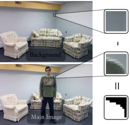
for health care applications and gaming. Generally, object segmentation on a static camera is done using background subtraction. Background subtraction is used for its simplicity and efficiency [23]. Ideally, background subtraction can be done by getting the absolute value of the subtracted image pixel values from the background model and the main image stream with the needed foreground. Any value greater than zero would be the background such as shown in figure 2.5a and 2.5b respectively. However, this is not usually the case since the background in the main image stream is never exactly the same the recorded background model, which results in background patches classified as foreground. This background inconsistency could be due to small illumination changes, camera image sensor quantization rounding, or just noise. A simple solution would be to use a threshold value instead of the zero mark to determine if the pixel location is a background pixel or a foreground pixel. Any result value below the threshold is a background pixel, and anything above is the foreground. However, this sometimes presents more problem than it solves.
Consider a person wearing clothing close in color to the background. If the difference in color between the background and the clothing is less than the assigned threshold, then a foreground pixel could be classified as a background one which would result in rough and fractional foreground objects such as the one shown in figure 2.5c.
2.2. LowLevel: Core technology 13
(a) Background Subtraction demo
(b) Thresholded Background subtraction ideal result (c) Rough Silhouette
Figure 2.5: Background subtraction
Moving camera
camera and the motion of the foreground object have to be taken into account. This requires some form of motion decomposition to separate the motion of the camera and the motion of the object. Two well used techniques are temporal difference and optical flow. Simply, both techniques try to measure the motion of the scene between consecutive frames, isolate the background depending on the analyzed motion and find the required foreground. In the scene of a moving camera, the closer an object is to the camera, the faster the displacement of that object is compared to the background.
Our approach will utilize the static camera mode, which means we will be using static camera segmentation methods. As a design built to be used for home monitoring, it would be pointless to complicate things and use a mobile camera. In addition to that, a mobile segmen-tation framework used in a multi camera setup would require far more performance resource usage since constant location update is required.
2.2.2
Feature extraction
2.2. LowLevel: Core technology 15
Figure 2.6: Pose estimation Examples [15] for more details.
Part of feature extraction is the human pose estimation. Human pose estimation techniques enable the development of accurate 2D or 3D representations of the human body. Such as the ones shown in figure 2.6.
2.2.3
Activity detection and classification
belongs to. In the other scenario, the system is to classify the name of the move a dancer is going. In this case, the feature algorithm generates a skeletal model with approximate 2D joint locations. The features can be dimensionally lowered by taking the angle of each joint at its vertex, lowering the total dimensions by one. In this case a K-Nearest neighbor classification algorithm might not be enough to classify the action, rather a more complicated probabilistic model such as Hidden Markov Model (HMM) might be needed to classify many action classes correctly.
The classification process always needs to be trained to identify the different classes of possible actions. Actions are highly variable in structure, so no two performances of the same action by the same person are the same. The classifier has to have the ability to classify actions performed by different subjects of different size and gender, as well take into account the variability of the performance in speed and style. It is always a challenge to design an action model that is highly adaptable to all forms of variation. Weinland et al. [27] provides a good representation of the action learning/classification data flow process as shown in figure 2.7. In Weinland’s model, the four key components work together to classify an action. The feature extraction extracts the required features which are fed into the action based components. The action classification component uses the action model database, which was generated using the action learning component, to classify the right action.
2.3. Mid level: HumanActivityRecognitionSystems 17
Figure 2.7: Action learning and classification [15] more complex action such as kicking a ball, cooking, etc.
2.3
Mid level: Human Activity Recognition Systems
The mid level Recognition system is designed to integrate with the low core technology by using the extracted results of the low core system. Based on Shian-Ru et al., there are three typical types of [15] human activity recognition systems:
• Single person activity recognition
• Multiple people interaction
• Abnormal activity recognition
In a system such as the health monitoring system, the single person activity recognition system would work best, since the algorithm is usually looking for known ”warning” actions that could trigger first response.
2.4
High level: Applications
Lastly, the high level, applications module, is what determines the application base and trans-forms the result of the previous two modules into usable form. In a health monitory system, that could translate into a phone call, or an alarm system signaling an abnormality in a person’s well being. Other forms of system exist, such as the entertainment system, and is what the Kinect camera was originally built for. Also, one of the highly required systems in the market is the surveillance system, which can be used, for example, as a quick warning system, or to aid staffmembers detect points of interest faster.
2.5
Motivation for the proposed approach
With an overall view of the system, in this thesis we will focus on the hardware and data fusion part of the home health monitoring system. With that in mind, we explore other related work to gain a better understanding of what is needed. The research will be presented in a logical order leading to the choice of design.
2.5.1
Single camera feature extraction and action recognition
2.5. Motivation for the proposed approach 19
Figure 2.8: Distance Space [4]
In the first example, Cheema et al. [4] demonstrated the use of binary silhouettes to extract key poses for action learning and recognition. The approach is designed with real time per-formance in mind, so the feature representation is a simple contour based pose representation. They start by finding the center of the extracted binary silhouette, and then from the center, measure a predetermined number of line lengths reaching the contour of the silhouette, eff ec-tively transforming the binary data into a distance space, as shown in figure 2.8. Key poses are recognized through the use of the K-means clustering classifier, and the pre-compiled MuHAVI data set (The MuHAVI data set is a public data set developed specifically for action recognition [26]). Based on the authors testing results, the test achieved good results at an average of 56fps using a regular laptop computer running matlab.
In another example, Dalal and Triggs [8] demonstrate the use of Histogram of Oriented Gradients (HOG) as a feature set for human detection. Compared to the previous example, the algorithm is built to detect the human ”object” rather than recognize actions. However, recognition is still needed to detect the present of the target object. They rely on the linear Support Vector Machines (SVM) classifier for object detection.
by exploiting people contour-point tracking. These related works, however, only attempt to address single camera scenarios. Many actions are hard to recognize with single views, and generally are not capable of handling occlusions. The shape and motion information vary greatly to represent a specific action efficiently, since this information is highly dependent of viewpoint.
2.5.2
Stereo camera setup
A multicamera setup aims at improving results in the action recognition field, especially where occlusions are present. However, this setup lacks any spatial data, and relies on 2D data. Different authors have attempted using stereo cameras to acquire depth data. Harville and Li [13] and Darrell et al. [9] used a stereo camera in their approach to extract the depth information in the attempt to better track multiple people in a frame. Both papers use the depth information to better segment the foreground from the background data, and extract silhouettes to work with. Although Cheung and Woo [6] have successfully attempted to deal with occlusions in a stereo camera setup, they are generally not as robust when it comes to occlusions as a multi view camera setup. Extracting 3D data is possible in a multi view setup, however computation cost is much higher than with a stereo camera setup, and might not be practical in real world applications.
2.5.3
Multi view camera setup
2.6. MicrosoftKinect 21
data. A similar approach has been demonstrated by Calderara el al. Instead of tracking an ob-ject as a whole, Calderara el al. aims at tracking a certain number of automatically segmented relevant areas of the human silhouette, which describe the motion for action recognition [2]. Their proposed approach employs the use of a multicamera setup, with the use of Mixture of Guassians for segmentation.
2.6
Microsoft Kinect
The Microsoft Kinect camera (Kinect will be used interchangeably with Microsoft Kinect throughout this thesis), is a Microsoft product originally built for the purpose of in game ges-ture recognition at an affordable price. However, developers quickly realized its potential, and its capabilities that could be matched to other state of the art depth sensing cameras, but with a much lower price tag. Kinect achieves comparable results to continuous wave amplitude Time of Flight (TOF) cameras when trying to extract depth information [17]. Many publications have already been made under the computer vision banner. Xia et al. developed a method to detect a human from different poses by using depth information from Kinect [29]. In a different publication by Xia et al., the authors attempt to use the method developed by Shotton et al. [25] to extract the 3D skeletal joint locations from Kinect’s depth image, and uses histogram of 3D joint location as features for their action recognition algorithm [30]. Kinect’s complementary nature of depth, and color data opens up many opportunities to solve problems in computer vision [12].
Kinect in a very low cost system with good results.
Kinect however is still a single device, and its ability to handle occlusions is not very ef-fective. Obdrzalek et al. [22] tested the reliability and accuracy of the Kinect’s human pose estimation based on Shotton et al.’s method. Obdrzalek et al. attempt to compare the Kinect pose estimation to more established pose estimation techniques used in motion capture. The depth accuracy of the Kinect depth sensor ranges from 1-4cm at a range of 1-4m. Their results conclude that the Kinect pose estimation fails in the presence of occlusions, even self occlu-sion of other limbs or facing away from the camera can result in inaccurate inferred results. However, when fully facing the camera, the Kinect achieves results comparable to motion cap-ture. Since the Kinect was originally build for the Xbox 360 gaming console, it was assumed that the user would constantly be facing the camera. See appendix A for Kinect hardware specifications.
2.7
Mutli view Kinect setup
2.8. Calibration 23
2.8
Calibration
2.8.1
Brief overview
Camera calibration is an important part in computer vision, and is used extensively in many applications, especially in distortion correction applications, also called geometric camera cal-ibration. The aim of this calibration is to estimate the parameters of pinhole camera model, such as the one shown in figure 2.9. An ideal pinhole camera model consists of a small aper-ture (pinhole) thats lets light into a light proof box that inverts the image and projects it on the opposite side of the box. A camera is a non-ideal pinhole camera due to the presence of a lens, which causes distortions in the projected image. Through the use of calibration, we can estimate the pinhole camera parameters, represented as a 3 x 3 matrix called the camera matrix or the matrix of intrinsic parameters, as shown in equation (2.1). The matrix of intrinsic parameters is an estimation of the camera’s internal properties, and these values are fixed as long as the same camera is used, and no zoom applied. Therefore, it is sufficient to estimate these parameters once.
A=
fx γ cx
0 fy cy
0 0 1
(2.1) Where:
• (cx,cy) is the principal point at the image center
• (f x, f y) are the focal length
• γis the skew of both axis in an image. Figure 2.10.
Figure 2.10: Pin hole camera Model (Exclusing the skew)
2.8. Calibration 25
[R|T]=
r11 r12 r13 t1
r21 r22 r23 t2
r31 r32 r33 t3
(2.2)
2.8.2
Single camera Calibration
Calibration is achieved by comparing a calibration object whose 3D geometrical pattern is precisely known. In our approach, we will be using the calibration technique developed by Zhang [32]. Zhang’s proposed technique is easier to implement than other known techniques such asThree-dimentional reference object-based calibration, and is more reliable and accurate thanself-calibrationtechniques.
Zhang’s method requires a camera to observe a planar pattern such as the captured chess-board pattern shown in figure 2.11b in two different orientation and compare it to the calibration object chessboard pattern with an exact known size as shown in figure 2.11a.
A vector is extracted from the inner boxes of the chessboard pattern in the captured image as well as the calibration object chessboard, such as the ones shown in figure 2.11d and 2.11c respectively. The image vector content is composed of 2D points, while the object vector content is composed of 3D points with the Z component assumed as zero since the chessboard is used as a plane. A 2D point is related to a 3D point by the equation
sme= A[R|t]Me (2.3)
where:
• s is an arbitrary constant
• meis an augmented 2D point to get homogeneous coordinates
• Ais the matrix of intrinsic parameters
(a) Chessboard pattern (b) Captured chessboard patter
(c) Recognized Chessboard pattern (d) Recognized captured chessboard pattern
Figure 2.11
• Me is an augmented 3D point to get homogeneous coordinates
Based on the assumption of a zero Z component, and without going into too much detail, Zhang’s method computes both the intrinsic and extrinsic parameters of a camera. In our approach, we use OpenCV (IntelR open source computer vision library). OpenCV implements
Chapter 3
Method Architecture and Justification
In this chapter, we present the architecture of the work in this thesis, justify the use of different methods, and explain the approach used in different components. The aim of our approach is to provide a basis for a more flexible pose estimation, action recognition and other computer vision applications. In our approach, we:
• Set up the depth sensing Microsoft Kinect camera and a non-depth camera in a multi view setup
• Use calibration methods to find both intrinsic and extrinsic matrix parameters of each camera
• Use the newly found intrinsic and extrinsic parameters to perform stereo calibration, and find the transformation matrix between the two cameras
• Extract the translation and Euler rotation matrices from the transformation matrix
• Use Shotton et al.’s [25] algorithm to estimate the human pose from the Kinect’s depth sensor data
• Use Project the Skeletal view from the Kinect’s image plane to the non-depth camera’s image plane using the found translation and Euler rotation matrices
• Fix calibration errors causing projection mismatch Use Kinect to find new Euler rotation matrices Use feedback iteration to find new translation matrix
3.1
Setup overview
3.1.1
Brief Introduction
Unlike a conventional camera setup, a multi-camera, or in this case, dual-camera setup, must know the physical constraints of the other camera to effectively be able to harness the advan-tages of a dual-camera setup. The aim of this setup is more health care oriented, so it should have the available properties to work in home environment with lots of furniture and possible occlusions. With that in mind, the system does not need a dynamic position monitor. Since the position of the cameras is going be fixed at the time of use, the location needs only be determined once, and updated only when the position of cameras need to be changed. How-ever, having some kind of error correction in case a camera is accidentally moved slightly from position would make things simpler to handle.
In any multi-camera setup, one camera has to be the center of reference. To make things easier, we will be using the Kinect camera as the center. As the center, the world axis origin would start from the Kinect camera, and the other camera’s physical constraints will provide relative distance between them.
3.1. Setup overview 29
3.1.2
Design
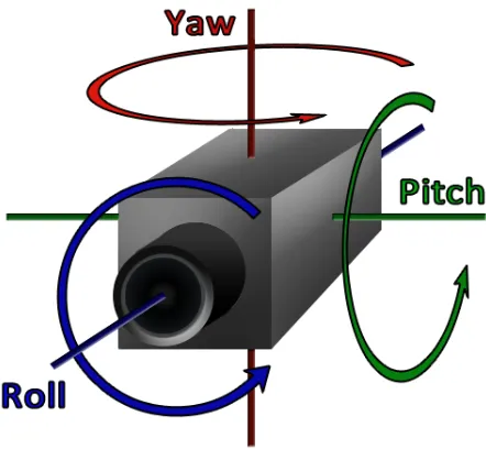
Unlike a single camera setup, spatial location of the cameras is a critical parameter that must be known. In a typical 3D world space, three degrees of freedom (DOF) are sufficient to know the exact location of the camera. However, this is not enough to define the direction that the camera lens is facing. An objects orientation in 3D space can be accurately defined using 3 dimensional Euler angles as shown in figure 3.1. This totals up to 6 DOF, and since we have two cameras, the total comes down to 12. However, working with 12 DOF in a highly variable space would make thing very complicated and resource intensive. For that reason, the number of DOF’s have to be lowered down.
Figure 3.1: 3 dimensional Euler angles
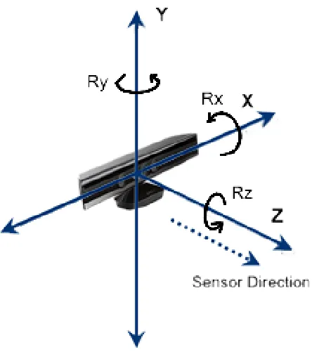
world axis to keep design simple. Figure 3.2 shows the axis layout of the Kinect camera.
Figure 3.2: Kinect axis directions and Euler angle orientation. TheY axis is towards the top of the camera, theXaxis is to the left, and theZaxis is in the Kinect camera lens direction
Since the cameras are fixed in their location, that generally means that they will be put on a flat surface. So practically, the cameras lens forward direction will be perfectly aligned with the horizontal plane (the plane parallel with the ground), and the lens’s left perpendicular side axis aligned with thexaxis. In other words, the camera will have a zeroRxandRzEuler angle component, the Pitch and Roll in figure 3.1 respectively. This might be true with regards to
Rz Roll, however, it was found that many cameras have a slightRx pitch with respect to the ground parallel horizontal plane by design, and even a small 5 degree inaccuracy could have negative effect on the end result. For that reason, to simplify the problem, only the RzEuler component will be considered to be zero. This leaves us with 5 DOF to work with, which is much better to deal with than 12 DOFs.
3.1. Setup overview 31
as long as the view from both cameras partially overlaps. The setup is build to work, even if one camera is higher from the ground than the other camera. Fixing the Kinect local axis with the world axis does not inhibit the Kinect from being moved. Rather, if the Kinect is moved, the world axis will be re-established at the Kinect’s local axis location.
Figure 3.3: A Dual Camera setup between the Kinect and a standard camera. The light triangle signifies the Kinect’s view area, and the darker signifies the standard camera’s view area. Both triangles intersect in the view overlap section
So far, this concludes the hardware setup. The next step is to build the software side for the setup to be of any use. The two cameras have to be aware of each others location and angle difference, and doing this manually, for example by using a measuring tape, is a tedious and error prone method. Since accuracy is critical, this is not an option. An accurate way to measure distance and angle difference between the two cameras can be achieved by using calibration techniques, more details can be found in section 2.8.
to construct two skeletal structures from two different views, but using only the resources to construct one, simplifying the algorithm to achieve the required real time performance.
Figure 3.4: Skeleton model [20]
We also will be introducing a new method to correct calibration errors, or accidental camera movement which might change the captured physical data. Figure 3.5 summarizes our main contribution and shows the process outline in more detail. The figure is also an outline of the logic flow of the software design. Check section 3.5 for more details.
3.1. Setup overview 33
Figure 3.5: Process breakdown
number of image and depth frames processed (We only cover the manual process in this thesis). If the interrupt results in a no match scenario, themain process loopstops and the calibration refinement process starts. This process extracts the body contour (body contour extraction), finds the center point of the extracted contour (center point extraction), estimates the new an-gle and distance values (angle correction and distance correction) and updates the database (Distance and Angle Database). The process then flows back into themain process loopwhere it resumes the pose estimation and projection processes until a user ends the process.
The next sections in this chapter will cover the following:
• Stereo calibration to get the relative distance and angle between each other
• Estimation of skeletal pose from depth data using Shotton et al.’s method in the paper
• Projection extracted skeletal data to the other camera’s image plane
• Error correction by segmenting body from the camera’s RGB color data and updating the new geometric data
3.2
Stereo-calibration
A single camera Calibration yields two matrices, the matrix of intrinsic parameters and the matrix of extrinsic parameters. The extrinsic parameter is the relation between the camera and in this instance, the calibration object. Knowing this, if both cameras were calibrated with the same chessboard pattern at the same time, as shown in figure 3.6, then the local axis position of each camera will be relative to the same arbitrary world axis. In this case, we have three point locations, camera 1, Kinect, and the world axis origin, and two rotation matrices. In our approach, we use OpenCV’s stereo calibration algorithm that uses these parameters to extract the relative parameters between the two cameras.
(a) Kinect View (b) Camera View
3.2. Stereo-calibration 35
(3.1) is a vector of the formtxi+tyj+tzkwhich defines the vector distance between the two
cameras’ axis. The rotation matrix in equation (3.2a) is a generalized matrix as the one shown in equation (3.2b). Each of the x,y,z component of the equation in (3.2b) is a matrix shown in equation (3.3a), (3.3b) and (3.3c) respectively. These matrices are then used in the skeletal projection part of this paper, section 3.3.3.
T =
tx ty tz
(3.1) R=
r11 r12 r13
r21 r22 r23
r31 r32 r33
(3.2a)
Rx(γ)=
1 0 0 0 cosγ −sinγ 0 sinγ cosγ
(3.3a)
Ry(β)=
cosβ 0 sinβ 0 1 0
−sinβ 0 cosβ
(3.3b)
Rz(α)=
cosα −sinα 0 sinα cosα 0 0 0 1
(3.3c) Now that we have the rotation and translation matrices, this concludes this section. In section 3.3.3 we will discuss how this information is used in the depth information sharing and skeletal projection to give two pose estimates from different views.
3.3
Pose estimation
In this section, we will present how the depth information is extracted, how a pose is estimated from the depth information, and how this information is shared with the other camera.
3.3.1
Depth extraction
3.3. Pose estimation 37
3.3.2
Skeletal extraction
Our method is based offof Shotton et al. in [25]. The method uses the advantages of depth over traditional intensity images by eliminating the need to deal with texture problems. This simplifies the background subtraction needed, which is usually a lot less reliable, and takes more processor power to deal with normal intensity images. The method then splits the body depth silhouette posture into a number of color coded labels such as the one shown in figure 3.7.
Figure 3.7: Shotton el al [25] depth image and ground truth body parts
3.3.3
Skeletal Projection
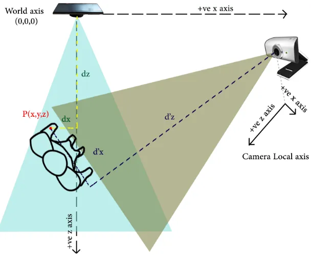
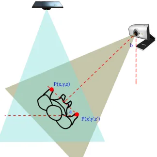
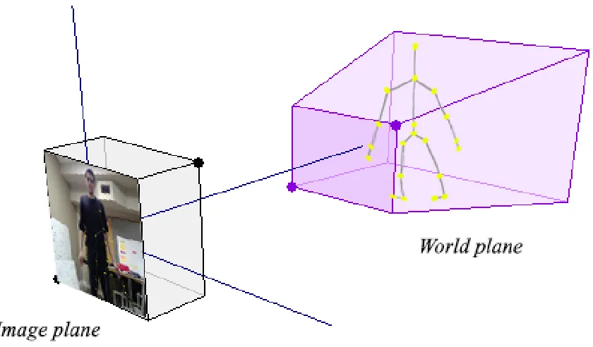
Before, we talked about depth information sharing between the Kinect and the camera. To do this, we have to transform the Kinect depth view plane to the camera view plane so that the depth values are with respect to the camera. Figure 3.8 gives a top view to serve a better understanding.
Figure 3.8: Kinect and camera in world axis. The figure shows the equivalent depth value of Kinect with respect to the other camera’s local axis. The Kinect is capable of depth values up to 3.5m, however, the other camera is not restricted with this value
For example, say point P with distance (x,y,z) from the world axis is a depth pixel in the Kinect plane, and we want to find its equivalent depth value from the webcam’s perspective. To do this, we will need to findd0x,d
0
y andd
0
zas shown in figure 3.8, whered
0
y (not shown in figure
3.3. Pose estimation 39
(3.3a), (3.3b) and (3.3c) respectively. However, since we are assumingαinRzis zero, as was
discussed in section 3.1.2, we will not be usingRzin the rotation process. This process is then
repeated for every depth pixel in the image. The resultant value can be see in equation, where N is the Nth depth value andP0x is the new transformed point value.
P0x(N)
P0y(N)
P0z(N)
=
1 0 0 0 cosγ −sinγ 0 sinγ cosγ
cosβ 0 sinβ 0 1 0
−sinβ 0 cosβ
Px(N)
Py(N)
Pz(N)
− Tx Ty Tz (3.4) However, these is one problem with this setup. The depth sensor has a resolution of 640x480 (Note that the depth resolution is not related to the RGB resolution since each is captured using different sensor components on the camera), which makes a total of almost 300K values to project, which will greatly impact performance. One way to solve this prob-lem would be to instead lower the resolution to 320x240, a total of 76K values, four times smaller than the higher resolution. Even at this value, the performance suffers, and reducing the resolution even further will render the approach not useful.
Our aim in our approach is to produce two pose estimations from two different cameras. So instead of projecting the depth values, we can project the pose estimation itself. Shotton et al. method generates 20 joints and 19 bones connected to these joints as shown in the skeleton model in figure 3.4. 20 joints is by far less than 76K, and projecting 20 should not have any impact on performance. However, this adds an extra step to the problem. Since the Skeleton is extracted in 3D meter coordinates, we will need to apply a 3D to 2D image pixel plane projection.
3.4
Calibration refinement
3.4.1
Overview
The whole skeletal projection step is heavily dependent on the success of the stereo calibration process. However, the stereo calibration was designed to handle cameras with a very similar view, that is, they are very close to each other, such as a stereo camera where the two lenses are right next to each other. Any small error in the measurements would produce unreliable results. Also, since the calibration process in our approach is a one time per setup, any small changes to the position of the cameras, say through accidental movement, would produce inac-curate results. To solve this problem, we proposed a feedback system that tries to correct any measurement errors.
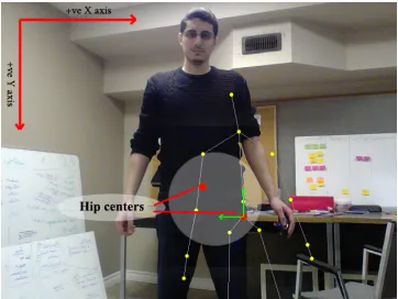
Before going into the technical details, let’s explain the logic flow. The method relies on a previous system calibration, and an upper body view of person in both cameras. We will start with Euler orientation correction. If a person was to stand upright facing the Kinect, with both arms to the side with a slight space between the wrists and the hips, such as the one shown in figure 3.10, then the angle at which the user is standing relative the camera can be extracted. Using this in a dual camera setup, the person faces the non-depth camera at a zero angle, and use the Kinect depth to find the angle at which the person is standing. This will lead to finding the horizontal angleRY in figure 3.2 between the two cameras. This approach cannot be used
to find the angle RX, however,RX is usually small, and fixing it is not as critical as fixing the
other parameters.
3.4. Calibration refinement 41
2D image pixel value and vise versa, would not work. The reason for that lies in the fact that we do not have any depth data available from the non-depth camera. This will be explained in more detail in section 3.4.3.
3.4.2
Angle correction
As was mentioned before, this step is a correction step, so previous calibration measurement is required. The method builds offof the previous calibration measurements, and tries to correct small changes. The first step is to find the new angle between the two cameras. When a skeletal projection misalignment is noticed by the user, they can invoke a correction parameter in the program. This can be automated, however its both resource heavy, and prone to false positives, since the method is designed to work with the person facing the two cameras. On a correction call, the program asks the user to stand facing the non-depth camera, but be in a position where the Kinect camera can see him, as shown in figure 3.9. Both hands must be visible to the Kinect camera, so that gives a limitation to the angle level that can be found.
We need two points in this method, one for the right hand PR, and one for left PL, and their value should be relative to the Kinect’s world axis. PRandPL each have 3 coordinates, (x,y,z), however, only the xandzcoordinates are needed for this method. If we extend a line between the two hands, such as the one shown in figure 3.9, then we can find the angle (a) at which the person is facing the Kinect camera using equation (3.5). Since the person is facing perpendicular to the line of sight of the non-depth camera, using triangle rules, we can find angle (b), where (b = 90o−a) is the relative Euler angle definingRY between the Kinect and
the non-depth camera.
a=tan−1
PL(z)−PR(z)
PL(x)−PR(x)
Figure 3.9: Finding the angle in the calibration correction step
3.4.3
Distance correction
The distance correction step is a bit more tricky than the previous step. Since depth information is not available in the non-depth camera, we can not reverse project, that is, use the 2D to 3D projection method. Instead, we will assume a constant depth value, and change the X and Y
value offset of the skeletal projection parameters to achieve a match between two reference points, one from the image data of the non-depth camera and one from the Kinect’s skeletal data, such as the one shown in figure 3.10.
3.4. Calibration refinement 43
Figure 3.10: Finding the distance difference between the two cameras
point can be extracted in a number of ways, including body segmentation using image process-ing techniques, silhouette dissection, etc. This will be explained in more detail in section 3.4.4. Figure 3.10 demonstrates the distance correction approach.
The next step is to distance match the two results. There are two requirement, first, the distance is estimated to determine if it falls within a certain threshold, and second, direction in which the skeleton has to move needs to be found. Based on the established direction and if the distance value is more than the threshold limit, the skeleton is moved in the 3D world coordinates using a predetermined default distance, usually 2 cm or so, both in theXand theY
Figure 3.11: 3D to 2D projection
3.4.4
Center Point extraction
In this step, we demonstrate the method used to extract the hip center of a wide stance position posture of person in an image. The approach is simplistic in design, and relies on geometric lo-cations rather than a recognition based system. Theoretically, the method can produce accurate results if the following criteria are met:
• The person is forward facing the camera
• A small part of the legs have to be shown
3.4. Calibration refinement 45
point for the calibration refinement process. In our design, our approach is meant to work even when part of the legs was cut offfrom the image such the one shown in figure 3.12e. So, in a scene with the legs not visible, the center point would not be the same as when the body silhouette is fully visible, causing the results of the process to be highly variable with each iteration, as is clearly shown in figure 3.12c and 3.12f.
The point of our approach is to produce a reasonably robust system capable of adapting to such situations. Based on Shotton el al.’s skeletal model, the center point is the HIP CENTER joint as the one shown in figure 3.4. The point lies somewhere between the Axilla (Arm pits) and the lower hips as shown in figure 3.12d and 3.12d. The center point has to be the same, regardless, to a reasonable degree, of limb visibility. To achieve this, we need to be able to find the Axilla and the hip joints on the silhouette.
(a) Extracted Silhouette (b) Edge detection and Normal center Point
(c) Edge detection and higher center Point
(d) Center Point
(e) Extracted Silhouette (f) Edge detection and Normal center Point
(g) Edge detection and higher center Point
(h) Center Point
To find the center point, we need to find four points, A, B, C and D labeled on figure 3.12d. After finding the center weight of the silhouetteS C, the silhouette’s contour is extracted. This can be done either using elastic Snake contours such as the ones used by Kass et al. in [14], or an edge detection algorithm. The latter being easier to use, we adopt that approach. Several edge detection algorithms are plausible, such as Sobel, Prewitt or Laplacian of Gaussian (LoG). LoG, having produced the best visual result, is used. We then use Dijkstra’s shortest path algorithm to extract a vector V[leng] of points around the extracted edge from the top point, around the silhouette to the same point again. The distance between the weight center and each vector point is calculated, and recorded in a new vectorVd. We then plot the vectorVdagainst
the vector’s position number to get a graph such as the one shown in figure 3.13a. The vector value is smoothed using a Gaussian filter to get the graph in figure 3.13b.
(a) Unsmoothed plot of contour distance from normal center Point
(b) Smoothed plot of contour distance from normal cen-ter Point
(c) Smoothed plot of contour distance from higher cen-ter point
(d) Smoothed plot of contour distance from higher cen-ter point, with legs not fully visible
3.5. Software 47
The idea of the approach is to find the local minimum from the graph that corresponds to the Axilla points A and D, and the center local minimum that corresponds to the groin area, which is used to find points B and C. However, as can be seen in plot 3.13b, points A and D do not achieve a local minimum. Instead, we increase the hight of the center pointS C using equation (3.6), where S C0 is the new weight center point and V[1] is the first value of the extracted contour which corresponds to the top point of the head. In other words, we are finding half the vertical (hence the Y component in the equation) distance of the current center pointS C and the top head pointV[1], and adding it toS C to find the new center pointS C0, shown in figures 3.12c and 3.12f. This step makes sure that both Axilla points achieve a local minimum on the graph, as can be shown in graph 3.13c. The approach also works well where legs are not fully visible as shown in graph 3.13d.
S C0Y =S CY+
V[1]y−S CY
2 (3.6)
In the final step, points A and D are found using the local minimum, and points B and C are found by finding the first two points that interest the horizontal line passing to the right and left of the groin local minimum. Using these four points, the image HIP CENTER equivalent point can be found by finding the intersection between the lines ¯ACand ¯BDas shown in figures 3.12d and 3.12h.
3.5
Software
in-Figure 3.14: Process outline
cluding the Kinect driver, to interface with the Kinect camera and extract the depth and image data, in addition to many useful tools. The Windows code is used mainly in the use of handlers for the Kinect SDK.
The code logic flow will be explain through the use of UML class diagrams and related back to the flowchart introduced in figure 3.5 to better understand how the different compo-nents of the contribution fit on the software side. To make the different components of figure 3.5 easier to reference, and for better viewing, we have included the same flowchart but with alphanumeric labels, shown in figure 3.14. The structure of the UML class diagram will be explained in parts, and the complete system is shown in figure 3.21 at the end of software sec-tion. As to make the explanation easier to understand, the figure 3.5 label references will be
3.5. Software 49
Figure 3.15:Main 1class
Figure 3.16:kinectCam and cameraclass
projected camera pose, and display the interface to control the program. Figure 3.15 shows
Main 1class.
The Main 1class uses the cameraclass to control the camera and start the video stream
F1. As for the Kinect, Main 1 uses the class kinectCam to start both video F1 and depth streamF5. The Kinect pose estimationF6is performed bygetSkeletalData(). Figure 3.16 shows thecameraandkinectCamclasses.
Figure 3.17:skeletalProjectionclass
Figure 3.18: calibCameraandstereoCalibclasses
interface. The calibration and stereo calibration processes are performed using the calibCam-eraandstereoCalibclasses shown in figure 3.18. This information is stored onto the database
F4 using theMain 1 operation updateData(...) which stores the information onto a text file. During program initialization, the transformation parameters are read from the file using
Main 1class operationupdatePV()so as to not require a new stereo calibration each time the program is started.
When a user invokes an interrupt for calibration refinementF8, theMain 1class operation
recalibrateResults() is used to start the calibration Refinement process through the
3.5. Software 51
Figure 3.19:recalibrationclass
distance correctF12are performed using thestartRecalib()operation. The new transfor-mation parameters are then passed back to Main 1 class where it updates the database and resumes the pose estimationF6and projectionF7processes.
The last classcreateButtonLayoutis responsible for creating the buttons layout used by the Main 1 and managing the mouse click callbacks to some operations defined inMain 1. ThecreateButtonLayoutclass structure is shown in figure 3.20.
3.5. Software 53
Testing and results
In the previous chapters, we described our method in detail and explain the logic flow behind each component. In this chapter, we describe the effectiveness of the proposed approach, find out the proper parameters to use, and discuss the results.
We will start by dividing the system into three sections, and testing each part individually. In the first part, we will be testing out the stereo calibration method to find its strengths and drawbacks. In the second part, we will be testing out the pose estimation of Shotton et al.’s method to find its pose estimation limitations, and our proposed projection of the estimated pose to find how well it works. In the third and last part, we will be exploring the capabili-ties of the proposed calibration refinement method, and make interpretations of its real world application potential from its results.
4.1
Stereo Calibration
The calibration process is an important part of the system. If the calibration is not accurate, then the results are not accurate. So gaining an understanding of the performance and limitations of the calibration process is important in order to be able to determine the cause of errors. Since the stereo calibration process is the first step in the approach, it will make problem isolation and analysis easier if its test data is available before proceeding into the main testing stage. In

![Figure 2.2: Features extraction categories [15]](https://thumb-us.123doks.com/thumbv2/123dok_us/7775060.1281792/22.612.183.447.75.329/figure-features-extraction-categories.webp)
![Figure 2.4: Action recognition System [15]](https://thumb-us.123doks.com/thumbv2/123dok_us/7775060.1281792/24.612.139.491.75.320/figure-action-recognition-system.webp)