Available online: http://edupediapublications.org/journals/index.php/IJR/ P a g e | 1214
Multipulse Ac–Dc Converters With Reduced Magntetics
Feeding Vector Controlled Induction Motor Drives For
Improving The Power Quality At The Point of Common
Coupling
M. Akhila1Dr.Samalla Krishna2 Mr.S.Srikanth3
1
M. Tech Student Deptt of of Electrical & Electronics Engg. Tudi Ram Reddy Institute of Technology&Sciences, [email protected]
2
Professors, & Principal. Tudi Ram Reddy Institute of Technology&Sciences, Hydearabad. [email protected]
3
Assistant Professor, Department of Electrical & Electronics Engg. Tudi Ram Reddy Institute of Technology & Sciences, Hydearabad. [email protected]
ABSTRACT
The main aim of project is auto transformer-based multipulse ac–dc converters with reduced magnetics feeding vector controlled induction motor drives for improving the power quality at the point of common coupling. The proposed 12-pulse ac– dc converter-based harmonic mitigator consists of an autotransformer along with a passive shunt filter tuned for 11th harmonic frequency. This results in the elimination of 5th, 7th, and 11th harmonic currents. Similarly, the proposed 18-pulse ac–dc converter based harmonic mitigator eliminates the 5th, 7th, 11th, 13th, and 17thharmonic currents, thereby improving the power quality at ac mains. The simulation results carried out on the developed of autotransformers-based ac–dc converters.
Index terms: Auto transformer based
multipulse ac–dc converter, induction motor, Power quality, Passive shunt filter
1.INTRODUCTION
In order to prevent the harmonics from affecting the utility lines negatively, an Standard 519 has been reissued in 1992 giving clear limits for voltage and current distortions. Several methods based on the principle of increasing the number of rectification pulses in ac-dc converters have
Available online: http://edupediapublications.org/journals/index.php/IJR/ P a g e | 1215 this paper, a novel autotransformer based
18-pulse ac-dc converter (Topology D‟), which is suitable for retrofit applications, where presently 6 pulse converter is being used, referred as Topology 'A', have been proposed to feed VCIMD. The proposed ac-dc converter results in elimination of 5th, 7th, 11th and 13th harmonics. A set of tabulated results giving the comparison of the different power quality parameters is presented for a VCIMD fed from an existing 6-pulse ac-dcconverter and different 18 pulse ac-dc converter. Moreover, the effect of load variation on various power quality indices is also studied. To demonstrate the effectiveness of proposed 18- pulse ac-dc converter feeding VCIMD. A laboratory prototype of the proposed autotransformer is designed and the developed and different tests have been carried out to validate the working of the proposed harmonic mitigator. The test results are found to be in close agreement with the simulated results under different operating and loading conditions.
2.HARMONICS
The typical definition for a harmonic is “a sinusoidal component of a periodic wave or\ quantity having a frequency that is an integral multiple of the fundamental frequency.” [1]. Some references refer to “clean” or “pure” power as those without any harmonics. But such clean waveforms typically only exist in a laboratory. Harmonics have been around for a long time and will continue to do so. In fact, musicians have been aware of such since the invention of the first string or woodwind instrument. Harmonics (called “overtones” in music) are responsible for what makes a trumpet sound like a trumpet, and a clarinet like a clarinet.
Electrical generators try to produce electric power where the voltage waveform has
only one frequency associated with it, the fundamental frequency. In the North America, this frequency is 60 Hz, or cycles per second. In European countries and other parts of the world, this frequency is usually 50 Hz. Aircraft often uses 400 Hz as the fundamental frequency. At 60 Hz, this means that sixty times a second, the voltage waveform increases to a maximum positive value, then decreases to zero, further decreasing to a maximum negative value, and then back to zero. The rate at which these changes occur is the trigometric function called a sine wave, as shown in figure 1. This function occurs in many natural phenomena, such as the speed of a pendulum as it swings back and forth, or the way a string on a voilin vibrates when plucked
3. OPERATING PRINCIPLE OF
PROPOSED SYSTEM
Variable frequency drives often have strict demands placed on them to mitigate harmonic distortion caused by non-linear loads. Many choices are available to them including line reactors, harmonic traps, 12-pulse rectifiers, 18-pulse rectifiers and low pass filters. Some of these solutions offer guaranteed results and have no adverse effect on the power system, while the performance of others is largely dependent on system conditions. Certain techniques require extensive system analysis to prevent resonance problems and capacitor failures, while others can be applied with virtually no analysis whatsoever.
Available online: http://edupediapublications.org/journals/index.php/IJR/ P a g e | 1216 performance of various harmonic mitigation
techniques and offering a quantitative analysis of alternatives for real life VFD Operating conditions. Since power distribution transformers frequently have impedance ratings between 1.5% and 5.75%, one would expect that source.
The use of AC line reactors is a common and economical means of increasing the source
impedance relative to an individual load. Line reactors are connected in series with the six pulse rectifier
diodes at the in put to the VFD, as shown in Fig
Fig1. AC line reactors connection at supply side
The typical harmonic spectrum data for a six pulse VFD load fed by a power supply with an Effective source reactance of 3%, 5% and 8% looks as follows:
.
These data represent the harmonics measured at the input to the six pulse rectifier and will reduce to lower percentages when measured further upstream, provided there are other linear loads operating on the system. If 20% of the system load is comprised of VFDs with 5% input impedance, and 80% has linear loads, the harmonic current distortion at the VFD input will be 35% THID, but only 7% at the supply transformer secondary. Typically costing less than 3% of the motor drive system, line reactors are the most economical means of reducing harmonics. Practical ratings can achieve 29% to 44% THID at the input to the six pulse
Tuned Harmonic Trap Filters: Harmonic Trap Performance:
Tuned harmonic filters (traps) involve the series connection of an inductance and capacitance to
Available online: http://edupediapublications.org/journals/index.php/IJR/ P a g e | 1217
Fig2 Harmonic Trap Performance with 0.25% source impedance
4. VECTOR CONTROL
The various control strategies for the control of the inverter-fed induction motor have provided good steady state but poor dynamic response. From the traces of the dynamic responses, the cause of such poor dynamic response is found to be that their air gap flux linkages deviate from their set values. The deviation is not only in magnitude but also in phase. The variations in the flux linkages have to be controlled by the magnitude and frequency of the stator and rotor phase currents and instantaneous phases. The oscillations in the air gap flux linkages result in oscillations in electromagnetic torque and, if left unchecked, reflect as speed oscillations.
This is undesirable in many high- performance applications. Air gap flux variations result in large excurs ions of stator currents, requiring large peak converter and inverter ratings to meet the dynamics. An enhancement of peak inverter rating increases cost and reduces the competitive edge of ac drives over dc drives. Separately
excited dc drives are simple in control because they independently control flux, which when maintained constant contributes to an independent control of torque. This is made possible with separate control of field and armature currents, which in turn control the field flux and the torque independently. Moreover, the dc motor control requires only the control of the field or armature current magnitudes. As with the dc drives, independent control of the flux and torque is possible in ac drives The stator current phasor can be resolved, say, along the rotor flux linkages, and the component along the rotor flux linkages is the field producing current, but this requires the position of the rotor flux linkages at every instant; note that this is dynamic, unlike in the dc machine. If this is available, then the control of ac machines is very similar to that of separately excited dc machines. The requirements of phase, frequency, and magnitude control of the currents and hence of the flux phasor are made possible by inverter control. The control is achieved in field
5. SIMULATION RESULTS
Available online: http://edupediapublications.org/journals/index.php/IJR/ P a g e | 1218
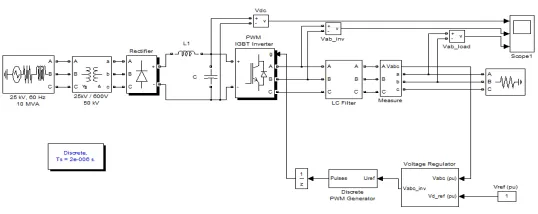
Fig 3. pulse AC-DC-AC Converter
Fig 4. DC Voltage, inverter voltage, load voltage
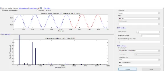
Fig5. THD % of Inverter voltage
Available online: http://edupediapublications.org/journals/index.php/IJR/ P a g e | 1219
2) PROPOSED 12 PULSE AC-DC CONVERTER
Fig 7. Proposed 12 Pulse AC-DC converter with harmonic trap
Fig 8. voltage and currents of Bus1 and Bus2
Fig 9. THD % of Current
CONCLUSION
The proposed harmonic mitigator has been observed suitable for retrofit applications with variable frequency induction motor drives operating under varying load condit ions.The performance of the proposed harmonic mitigator fed VCIMD under varying load conditions is
Available online: http://edupediapublications.org/journals/index.php/IJR/ P a g e | 1220 voltage, power factor and crest factor. On the dc
link side too, there is a remarkable improvement in ripple factor of dc link voltage.
REFERENCES
1.P.Vas, Sensorless vector and direct torque control, Oxford Universit Press, 1998.
2. IEEE Guide for harmonic control and reactive compensation of Static Power Converters, IEEE Std. 519-1992. 3. D. A. Paice, Power Electronic Converter Harmonics: Multipulse Methods for Clean Power, New York, IEEE Press 1996.
4. S.Martinius, B.shalimi and
P.A.Cahono, "A transformer connection for multipulse rectifier applications," Proc. Int. Conf. Powercon,
Oct.2002,vol.22,pp.1021-1024
AUTHOR’S PROFILE
DR. SAMALLA KRISHNA so far has successfully guided many post graduate students in the fields of Signal and Image Processing, Neural Networks and Pattern Recognition while several other students are being supervised by him in a wide variety of other fields like DSP, Medical Image Processing and Object Recognition in addition to this he supervised many electrical and other disciplinary engineering students .He served as an academic supervisor to more than 300 Bachelor Degree dissertations towards the award of Undergraduate Degree ,and He has published
more than 35 research papers in reputed International Journals. He shared his research experience more than many podiums like conferences, workshops, seminars and symposia. And currently he is working as a professor in TUDI Group of institutions, Hyderabad. He has 12 years of experience in the teaching and research field. His many research articles are cited by scholars and research institutions.
MR. S.SRIKANTH is a Post Graduated from the field of Electrical Engineering. He has 3 years of teaching experiences for Graduate and Post Graduate engineering courses. He has published her research work many International Journals and conferences. He guided several engineering students for their academic projects.