AUTOMATIC IMAGE RETARGETING USING
SALIENCY BASED MESH PARAMETERIZATION
1S.Sai Kumar, 2A.Sudhir Babu
Department of Computer Science Engineering PVP Siddhartha Institute of Technology, Vijayawada, Andhra Pradesh, India.
1E-mail:[email protected]
2E-mail:[email protected]
Abstract— Automatic image retargeting is used for large image.That are to be fit in small size display devices. Without any loss of information.our proposed methods one is saliency based mesh parameterization method is used to retarget the image. Stretch-Based Mesh Parameterization is generating on saliency image. Graph-Based visual saliency is used to easily find out the objects in the image. Mesh Generation on that saliency object part it should be retarget the image. Another method is comparison of seam-carving and Automatic retargeting method. In this we show the same image as differentiate by axes to separate one is loss of information and structure of the image is changed is called seam-carving. Another one is without loss of information and should not change the structure of the image is called retargeted method.
Key words:Automatic image retargeting, Mesh parameteriztion,seam-carving.
I. INTRODUCTION
Now a days mobile devices like cellular phones,PDA’s are increasing more and more.these are all portable display image functionalities. Mobile devices having small screens[1] with different aspect ratio and much more highest resolutions.Those are to be fit in target display. The problem of adapting the images to fit in various trget screens by using image retargeting. A common functioality of image retrgeting is to rescale the original image according to the target screen size. Scaling method has the problem. That is some important portion of the image should be decreased. So visual distortion is introduced. The next method is cropping to retarget the image. It is used to crop the important area of the image. The main disadvantages of cropping are contextual content of the particular image to be re moved. Another method is seam-carving [4] [6]. In this image resizes by iteratively remove the low resolution pixel values. The main drawback of seam-carving is to break the objects of the image. So image structure is changed. The last method for image resize by using mesh parameterization [8]. In this mesh is generation on
color images. Where we select the objects from the image is manually by using blue edge. Reduce the edges of the objects and to fit in target size. It also has the disadvantage that is mesh generation on color image is more time taking processes. To find out the threshold values of the image it takes lot of time. Another one is by selecting the objects of the image is manually. To overcome these problems our method is introduced that is Automatic image retargeting [3] using saliency [2] based mesh parameterization. In this we define two areas one is saliency based mesh parameterization and another one is comparison of seam-carving and retargeting methods.
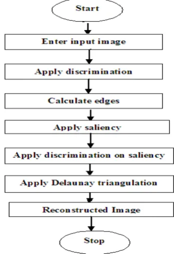
Now our proposed method
Initially taken the input color image.
Input image is discriminated by row-column wise.
Calculate the edges by using CANNY EDGE DETECTION algorithm.
Apply saliency to change the color image to Gray- Scale image. Where the objects are found it takes high resolution and it indicates white color, low resolution indicates black color.
The saliency image is to be discriminated by row-column wise. Where the high resolution is found it indicates black discrimination points, low resolution indicates white discrimination points.
Apply Stretch-Based Mesh Parameterization and using Delaunay Triangulation to retarget the image. With out any loss of information.
To produce the retarget image.
Comparison of seam-carving and automatic retargeting methods.
II.RELATEDWORK
image is uniformly down sampled to fit the target screens. Important objects in the image are often small and difficult to identify. To account for different aspect ratios, either the distortion caused by aspect ratio change is introduced or black letter box is used to fill in the blank space, thus wasting the precious space. Many methods identify an important region in the image and crop this region to fit target screen. These methods usually rely on image analysis, such as attention model extraction and object detection, to identify the important region. Cropping-based retargeting methods can effectively preserve important information of the original image, at the expense of losing valuable context information. A fish-eye view warping scheme to achieve the goal of emphasizing the important region while retaining the surrounding context. This method can effectively achieve the focus + context view of the original image. However, it creates noticeable distortion, especially in the contextual region. Seam-carving method for resizing images. Their method iteratively carves unnoticeable seams to reduce the image size. However, it often breaks image structures since the carving procedure only relies on low-level saliency information and fails to consider image structures. Both Setlur et al. and Cheng et al. proposed context re composition for preserving salient information. These methods first segment salient objects based on the detected saliency prior. Then they fill in the holes left after object segmentation. Finally, they compose salient objects back onto the resized background video frames based on a set of aesthetic criteria.
II. RETARGETING SALIENCY BASED MESH
PARAMETERIZATION
Image retargeting attempts to adapt a source image to display of smaller size [1]. And different aspect ratio than originally intended. We formulate image retargeting as a mesh parameterization problem that emphasizes the important content while retaining the surrounding background with slight distortion. To emphasize the input image is taken, then apply the discrimination of the input image and calculate the edges of the input image (Section III-A). To emphasize salient objects in image, we first calculate a saliency map of the source image and apply the discrimination of the saliency map image (Section III-B). Then we build a controlling mesh of the saliency map image that is consistent with the underlying image structures, and associate the saliency information with the source mesh (Section III-C). In this way, retargeting is transformed into a parameterization problem of finding a target mesh with the desired resolution. In order to improve visual quality of the target image, we interpret preservation of saliency and image structure information as constraints of parameterization .Afterwards, to generate target size of saliency image is solved by a constrained stretch-based mesh parameterization scheme. Automatic image retargeting algorithm to generate retargets image size. With out any information loss and also compare the seam-carving and image retargeting (Section III -D).
A. Importance Computation
Given Input Image
Fig : 1 Indicates given input Image .
Input Image After Discretization
Fig : 2 Indicates input Image after Discritization.
Flow-Chart of Saliency Based Mesh Parameterization
In this section we can read the input image, and that can be discritized by using row wise- column wise discretization. In this Discretization to equal portioning points is generated by rows and columns. It is used to easily identify the object of the image. After that we find out the edges of the image by using Canny Edge Detection Algorithm.
Canny Edge Detection Algorithm
EDGE IMAGE
Fig: 3 Indicates to find the Edges.
The Canny algorithm uses an optimal edge detector based on a set of criteria which include finding the most edges by minimizing the error rate, marking edges as closely as possible to the actual edges to maximize localization, and marking edges only once when a single edge exists for minimal response [1]. According to Canny, the optimal filter that meets all three criteria above can be efficiently approximated using the first derivative of a Gaussian function equation (1), (2).
G (k, l)
=
22 2
2 2
2
1
l k
e
(1)
k
l
k
G
(
,
)
k
22 2
2
l k
e
l
l
k
G
(
,
)
l
22 2
2
l k
e
(2)
The first stage involves smoothing the image by convolving with a Gaussian filter. This is followed by finding the gradient of the image by feeding the smoothed image through a convolution operation with the derivative of the Gaussian in both the vertical and horizontal directions. The 2-D convolution operation is described in the following equation (3).
Where: g(k,l) = convolution kernel
I(x,y) = original image
I’(x,y) = filtered image
2N + 1 = size of convolution kernel
Both the Gaussian mask and its derivative are separable, allowing the 2-D convolution operation to be simplified. This optimization is not limited to software implementation only, but applies to hardware implementation as well, as shown in the next section. The non-maximal suppression stage finds the local maxima in the direction of the gradient, and suppresses all others, minimizing false edges. The local maxima are found by comparing the pixel with its neighbors along the direction of the gradient. This helps to maintain the single pixel thin edges before the final thresholding stage. Instead of using a single static threshold value for the entire image, the canny algorithm introduced hysteresis thresholding, which has some adaptively to the local content of the image. There are two threshold levels, th, high and tl, low where th > tl. Pixel values above the th value are immediately classified as edges. By tracing the edge contour, neighboring pixels with gradient magnitude values less than th can still be marked as edges as long as they are above tl. This process alleviates problems associated with edge discontinuities by identifying strong edges, and preserving the relevant weak edges, in addition to maintaining some level of noise suppression. While the results are desirable, the hysteresis stage slows the overall algorithm down considerably. The performance of the canny algorithm depends heavily on the adjustable parameters, σ, which is the standard deviation for the Gaussian filter, and the threshold values, th and tl. σ also controls the size of the Gaussian filter. The bigger the value for σ, the larger the size of the Gaussian filter becomes. This implies more blurring, necessary for noisy images, as well as detecting larger edges. As expected, however, the larger the scale of the Gaussian, the less accurate is the localization of the edge. Smaller values of σ imply a smaller Gaussian filter which limits the amount of blurring, maintaining finer edges in the image. The user can tailor the algorithm by adjusting these parameters to adapt to different environments with different noise levels. Results can be further improved by performing edge detection at multiple resolutions using multi-scale representations, similar to the Marr-Hildreth algorithm [1]. This is achieved using different standard deviations, which correspond to different resolution versions of the image. Edges have zero crossing at multiple scale values.
B. GBVS Saliency Constraint
by using the approaches proposed and then build the final saliency map using the iterative method proposed .As illustrated in saliency attention is determined by the number of saliency regions and their brightness, area, and position in the gray saliency map [5], as shown in Fig. 4. However, in order to reduce adaptation time we binarize the saliency map to find the regions that most likely attract human attention, i.e., using a binarization threshold on brightness, which is estimated adaptively. Thus the saliency attention value is (4).
kl saliency kl
R l k
saliency
B
W
AV
( , ).
(4)Fig: 4 Indicates Saliency Attention Detection.
Where denotes the brightness of pixel point () in the saliency region , and
is the position weight of that pixel. Since people often pay more attention to the region near the image center, a normalized Gaussian template centered at the image is used to assign the position weight. Now our experiment results of the saliency map of the image is
Fig: 5 Indicates After Applying a Saliency Map.
Fig: 6 Indicates saliency map overlaid.
Discretization of saliency part of the image
Fig: 7 Indicates Discritization Saliency part of the Image. The above figures indicating the input image can be converted into saliency map due to find out the objects where in this white color indicate the objects are present in the image, and black color indicates background of the image Discrimination saliency map is the technique which is used to discritizes the objects and background where black point indicates the object of the image and white points indicates the background of the image.
C. Constrained Mesh Parameterization
Delaunay Triangulation
Fig: 8 Indicates to construct Delaunay Triangulation mesh
Reconstructed Image x2
Fig: 9 Indicates Retargeted saliency image.
Fig: 10 Indicates Retargeted saliency image
original image GBVS map
The Stretch-Based Mesh Parameterization
With the calculated edge lengths, M0 can be obtained by one stretch-based parameterization method. Mesh parameterization has been extensively studied in computer graphics [8], [9]. These methods take different metric criterions as the objective of energy minimization process Among them. Stretch-based methods work well when reducing the global mesh distortion [10]. Our concern is computing one 2D-to-2D parameterization, which is different from the aforementioned 3D-to-2D process (Fig. 10).
We first describe some related notations. Let {Pi = (Xi, Yi) |I=1,…..,n} denote the nodes of M. {Si= (Ui , Vi)|i=1,….n} Represent the corresponding nodes of M0 to be solved in texture space.M0 has the same topology as M, Si Corresponds to Pi, and edge (Si, Sj) corresponds to (Pi, Pj).
The 3D length lij of (Si, Sj) is obtained using the aforementioned method. M0 is completely characterized by the lengths of its edges. As each edge of M0 has been figured out, M0 can be computed by minimizing the following energy function equation (5).
2 2 2 2 ) , (
)
||
(||
kl kl l k edges l k tn
n
S
S
E
(5)Exploiting the symmetry of the above equation, energy gradients on point Si are in equation (6).
8 k t u E 2 2 2 2 ) , ( (|| || ) .( ) kl l k kl l k edges l k n u u n S
S
8 k t v E 2 2 2 2 ) , ( ) .( ) || (|| kl l k kl l k edges l k n v v n S
S
(6)
When M is dense, directly solving the above equations may cause adjacent triangles of M0 to flip over, leading to invalid topology. This is caused by inverting the orientation of the three points of triangle. To tackle this issue, we revise the energy function by penalizing the orientations of triangles using the sgn function.
Assume that the adjacent triangles incident upon edge (Si, Sj) are TS1 = T (SiSjSk2) and TS2 = T(SiSjSk2). Their corresponding triangles in the input image are
Fig: 11 The orientation of the triangles (a) in image space should keep Consistent with that of their corresponding ones (b) in retargeted texture space.
TP1 = T(PiPk1Pj), and TP2 = T(PiPjPk2). For each pair of corresponding triangles, the orientations of points should be equal.
To achieve this, we define the equation (7).
)
7
(
)
,
det(
).
,
det(
)
,
det(
).
,
min(det(
sgn
2 1 2 2 1 1 1 1
k j k i k l k k k j k i k l k k ijP
P
P
P
S
S
S
S
P
P
P
P
S
S
S
S
W
The energy function is then transformed into equation (8).
2 2 2 2 ) , (
)
||
||
.
(
kl kl l k edges l k tn
n
S
S
wij
E
(8)
Where the coefficient wij penalizes the triangle in M0 .whose orientation of points flips over with respect to its corresponding Triangle in M. If so, wij is chosen as _1, otherwise, þ1. With this energy function, a valid mesh in texture space is obtained. Minimal value of (8) is computed by the multidimensional Newton’s method. For each iteration of Newton’s method, one multigrain solver is adopted for solving the sparse linear equations. In practice, it converges to the final solution within several seconds. Once M0 is obtained with the parameterization process, a new texture can be mapped onto the ROI of the input image. Since the parameterization takes into account the underlying geometry of ROI, the new texture deforms naturally with respect to the underlying surface. Our experimental results demonstrate that the distortion effects of the new textures are visually pleasing.
D. Automatic Image retargeting method Flow –Chart of Automatic Image
Retargeting method
Automatic image retargeting algorithm to generate retargets image size. With out any information loss and also compare the seam-carving and image retargeting.
Apply seam-carving method [4]. In this image resizes by iteratively remove the low resolution pixels. Seam-carving is to break the objects of the image. So image structure is changed of images. This Seam Carving is a technique
proposed by Avidan and Shamir for content-aware resizing technique belongs to the category of pixel removing. The basic idea is to remove paths of low energy pixels (seams)
from top to bottom or from left to right which are not so important for the understanding of the image content. The removal of each seam causes a reduction of the image size by one where vertical seams reduce the width and horizontal seams reduce the height.
Fig: 12 Left: Original image. Center: The color indicates the order of the seams (white seams with low energy are removed first; red seams are preserved as long as possible). Right: Image after the seams have been removed.
The Automatic image retargeting method is a technique is not only for content-aware resizing belongs to the category of pixel removing and also remove low energy pixels but without loss of information.
Seam-carving retargeting method
Fig: 13 left images indicate seam-carving and right image indicates retargeting method
Seam-carving retargeting method
Fig: 14 left images indicate seam-carving and right image indicates retargeting method.
LIMITATION
Our method retargets images with salient objects by a process of saliency-based mesh parameterization. Salient object extraction relies on image saliency and face detection. Since 2D image is prone to variations of body poses, face expression, and illumination, the robust human face and body detection is still challenging. This makes accurate salient object extraction difficult. In our test examples, our method fails to capture some important human bodies with varied face poses or illumination. It is one drawback of our approach.
CONCLUSION AND FUTURE WORK
We have proposed an effective Automatic image retargeting on saliency based mesh parameterization method based on a mesh image representation. For the first time, we formulate image retargeting as a Saliency based mesh parameterization problem that aims to find a homomorphous mesh with the desired size of the target display. Our method achieves emphasizing important objects while retaining the surrounding context. Our scheme of using mesh representation for image adaptation enables easy preservation of images structures. In future, texture mapping on retargeted image to generate color image.
REFERENCES
[1] [1] L.-Q. Chen, X. Xie, X. Fan, W.-Y. Ma, H.-J. Zhang and H.-Q. Zhou, “A visual attention model for adapting images on small displays” Multimedia Syst., vol. 9, no. 4, pp. 353–364, 2003.
[2] V. Setlur, T. Lechner, M. Nienhaus, and B. Gooch, “Retargeting images and video for preserving information saliency,” IEEE Computer. Graph.Appl., vol. 27, no. 5, pp. 80–88, Sep. /Oct. 2007.
[3] V. Setlur, S. Takagi, R. Raskar, M. Gleicher, and B. Gooch, “Automatic image retargeting,” in Proc. 4th Int. Conf. Mobile and Ubiquitous Multimedia, 2005.
[4] S. Avidan and A. Shamir, “Seam carving for content-aware image resizing,” ACM Trans. Graph., vol. 26, no. 3, pp. 267–276, 2007.
[5] L. Itti, C.Koch, and E. Niebur, “A model of saliency-based visual attention for rapid scene analysis,” IEEE Trans. Pattern Anal. Mach. Intel., vol. 20, no. 11, pp. 1254–1259, Nov. 1998.
[6] F. Liu and M. Gleicher, “Automatic image retargeting with fisheye view warping,” in Proc. ACM UIST, 2005, pp. 153–162.
[7] Y. Li, Y.-F. Ma and H.-J. Zhang, “Salient region detection and tracking in video,” in IEEE Int. Conf. Multimedia and Expo, 2003, pp. 269–272. [8] Yanwen Guo, Feng Liu, Jian Shi, Zhi -Hua Zhou, “Image Retargeting Using Mesh Parameterization,” IEEE Transaction on Multimedia, VOL. 11, NO. 5,
EXPERIMENTAL RESULTS
B C
The original size of the image is 800*600, The above Fig A, B, C is the experimental results of our paper (A) result of size 320*320, (B) results of size 320*240, (C) results of size 512*270