IJEDR1403080
International Journal of Engineering Development and Research (www.ijedr.org)3306
A Comparative Study of Different Shaped Patch
Antennas with and Without Slots
1
Swati Shrivastava
, 2Abhinav Bhargava
1Student, 2Assistant Professor
GGITM, Bhopal
________________________________________________________________________________________________________
Abstract - In this paper we are presenting the design of a single feed, compact size, single layer, Rectangular, square and Circular micro strip patch antennas for WLAN and WiMAX applications. Comparative study has been done to compare various parameters of these patch antennas with and without slots, For the design and simulation of it we have used the method of EM Simulation software I3ED. The antennas are designed on a “Roger ultralum” substrate with 2.5 dielectric constant, Comparison have been done on the factors like bandwidth, return loss and gain.
Keyword - Compact, WLAN, Wi-MAX, bandwidth, return loss, gain
________________________________________________________________________________________________________
I.INTRODUCTION
In communication system Wireless technology has popularly increased and Antenna is one of the fundamental part of these system. Wireless local area network (WLAN) and the Worldwide Interoperability for microwave Access(Wi-MAX) technology is speedily growing area in the contemporary wireless communication system. This gives user to flexibility to move in a broad coverage area and still be remain in the network, this brings the ease, freedom and flexibility. Wireless has become popular due to ease of installation and location freedom, Naturally these application require antennas. This being the case handy antenna technology has rapidly grown along with mobile and cellular technologies. It is important to have the appropriate antenna for a device. The proper antenna will definitely improve transmission and reception. The study of communication system without understanding the design and fabrication of antenna is incomplete.
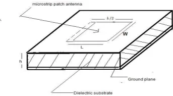
A micro strip patch antenna is contrive by engraving the antenna component pattern in metal trace bordered to an insulating dielectric substrate, similar to a printed circuit board, with a extended metal layer bonded to the opposite side of the substrate which structures a ground plane as shown in the figure 1. Low dielectric constant substrates are generally preferred for maximum radiation. The conducting patch can hold any shape but rectangular ,square and circular configurations are the most acceptably used configurations. Although the micro strip antenna has some of shortcoming till this date such as low gain, narrow operating bandwidth, poor radiation efficiency, but this can be significantly improved by cutting slots on the ground plane. In this study 6 antennas are compared on various parameters such as bandwidth ,return loss and gain. The study is done on rectangular, square and circular patch antennas with and without slots.
Fig 1
II.ANTENNA DESIGN
For comparison we have taken mainly 3 antenna shapes i.e. rectangular patch, square patch and circular patch and each one is compared with and without slots on the ground plane.
A. Rectangular patch Antenna layout
The length (L) and Width (W) of Antenna1 are calculated from Conventional equations[2]
IJEDR1403080
International Journal of Engineering Development and Research (www.ijedr.org)3307
√
where Leff=Effective length of the patch, ∆L/h=Normalized extension of the patch, εreff=Effective dielectric constant. The length
and Width of the Rectangular micro strip patch antenna are 11.74mm and 15.73mm respectively with substrate thickness h=1.6mm with 2.5 dielectric constant, Figure 2 and 3 shows the geometry of rectangular patch micro strip antenna without and with slots respectively . .
Fig 2 Structure of Rectangular Microstrip patch Antenna (without slot)
Fig 3 Structure of Rectangular Microstrip patch Antenna(with slot)
A=D=Cut Width=0.5mm, B=Cut Depth=3.5mm C=Cut Depth=9.5mm, E=Cut Depth=4mm F=Cut Depth=9.125mm Location of Probe= (0.375mm, 2.5mm)
B. Square patch Antenna Layout
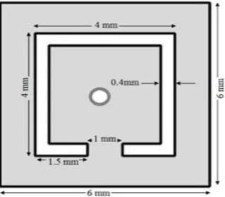
The proposed antennas consist of square patch of dimensions 6X6mm2. antennas are designed on a “Roger ultralum” substrate with 2.5 dielectric constant and thickness of 1.57mm.Figure 4 and 5 shows the geometry of square patch without slots and with a slot at the ground plane respectively.
IJEDR1403080
International Journal of Engineering Development and Research (www.ijedr.org)3308
Fig 5 Structure of square Microstrip patch Antenna(with slot)Sides = 6mm
C. Circular Patch Antenna Layout
The radius of the circular microstrip patch antenna is calculated from conventional formula.[3]
⁄
√
Thus, The radius of the circular microstrip patch antenna operating at frequency 5.8GHz is 6.83mm.Figure 6 and 7 shows the ge-ometry of circular patch without slots and with slots respectively.
Fig 6 Structure of square Microstrip patch Antenna(without slot)
Fig 7 Structure of square Microstrip patch Antenna(with slot).
III.ANTENNA RESULTS
Simulated results using Simulation software I3ED for comparison of various parameters for without slots and slotted rectangular, square and circular Microstrip patch antenna's are tabulated in table-1.
Table 1
Antenna Resonant Frequency (GHz) Return loss (dB) Band width (MHz) Gain (dBi)
Antenna 1 5.547 -29.56 183 5.3
Antenna 2 5.726 -25.34 156 5.2
Antenna 3 6.364 -25.51 220 6.22
Antenna 4 6.364 -20.60 220 6.43
Antenna 5 6.701 -13.08 60 3.71
IJEDR1403080
International Journal of Engineering Development and Research (www.ijedr.org)3309
Where, Antenna 1 and 2 are rectangular patch micro strip antenna without and with slots respectively. Antenna 3 and 4 are square patch micro strip antenna without and with slots respectively. Antenna 5 and 6 are circular patch micro strip antenna without and with slots respectively.
It has been observed that the results are better in case of slotted antenna as compared to conventional antennas. Simulated results of each parameters are shown, from figure 8 to 13 we can see return loss.
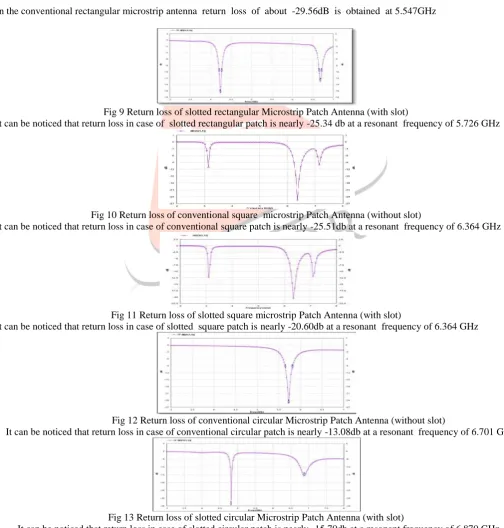
Fig 8 Return loss of conventional rectangular Microstrip Patch Antenna (without slot)
In the conventional rectangular microstrip antenna return loss of about -29.56dB is obtained at 5.547GHz
Fig 9 Return loss of slotted rectangular Microstrip Patch Antenna (with slot)
It can be noticed that return loss in case of slotted rectangular patch is nearly -25.34 db at a resonant frequency of 5.726 GHz
Fig 10 Return loss of conventional square microstrip Patch Antenna (without slot) It can be noticed that return loss in case of conventional square patch is nearly -25.51db at a resonant frequency of 6.364 GHz
Fig 11 Return loss of slotted square microstrip Patch Antenna (with slot) It can be noticed that return loss in case of slotted square patch is nearly -20.60db at a resonant frequency of 6.364 GHz
Fig 12 Return loss of conventional circular Microstrip Patch Antenna (without slot)
It can be noticed that return loss in case of conventional circular patch is nearly -13.08db at a resonant frequency of 6.701 GHz
Fig 13 Return loss of slotted circular Microstrip Patch Antenna (with slot)
IJEDR1403080
International Journal of Engineering Development and Research (www.ijedr.org)3310
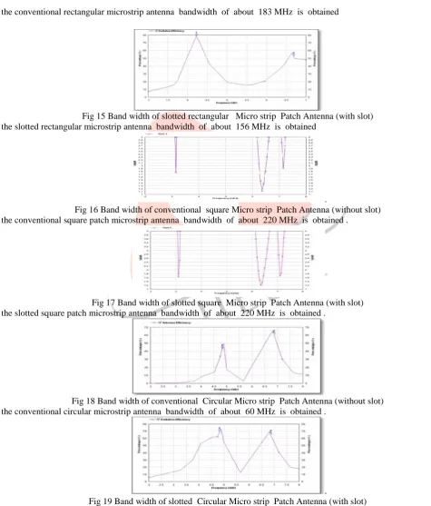
Figure 14 to 19 shows the antenna efficiency of different shaped patch antennas, it depicts the bandwidth of each antenna.Fig 14 Band width of conventional rectangular Micro strip Patch Antenna (without slot)
In the conventional rectangular microstrip antenna bandwidth of about 183 MHz is obtained
Fig 15 Band width of slotted rectangular Micro strip Patch Antenna (with slot) In the slotted rectangular microstrip antenna bandwidth of about 156 MHz is obtained
.
Fig 16 Band width of conventional square Micro strip Patch Antenna (without slot) In the conventional square patch microstrip antenna bandwidth of about 220 MHz is obtained .
Fig 17 Band width of slotted square Micro strip Patch Antenna (with slot) In the slotted square patch microstrip antenna bandwidth of about 220 MHz is obtained .
Fig 18 Band width of conventional Circular Micro strip Patch Antenna (without slot) In the conventional circular microstrip antenna bandwidth of about 60 MHz is obtained .
.
IJEDR1403080
International Journal of Engineering Development and Research (www.ijedr.org)3311
Figure 20 to 25 shows the radiation pattern of different shaped patch antennas, it depicts the gain of each antenna.Fig 20 Gain of conventional rectangular Micro strip Patch Antenna (without slot)
In the conventional rectangular microstrip antenna gain of about 5.3 dBi is obtained at 5.547 GHz
Fig 21 Gain of slotted rectangular Micro strip Patch Antenna (with slot)
In the slotted rectangular microstrip antenna gain of about 5.2 dBi is obtained at 5.726 GHz.
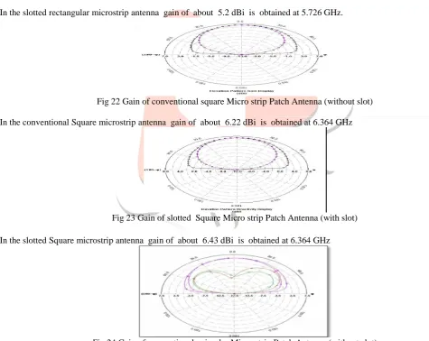
Fig 22 Gain of conventional square Micro strip Patch Antenna (without slot)
In the conventional Square microstrip antenna gain of about 6.22 dBi is obtained at 6.364 GHz
Fig 23 Gain of slotted Square Micro strip Patch Antenna (with slot)
In the slotted Square microstrip antenna gain of about 6.43 dBi is obtained at 6.364 GHz
Fig 24 Gain of conventional circular Micro strip Patch Antenna (without slot)
IJEDR1403080
International Journal of Engineering Development and Research (www.ijedr.org)3312
Fig 25 Gain of slotted circular Micro strip Patch Antenna (with slot)In the slotted circular microstrip antenna gain of about 4.43 dBi is obtained at 6.870 GHz.
IV.CONCLUSION
In this paper a comparative study of rectangular, square and circular patch antenna's have been done, different parameters have been compared on without and with slots structure of each antenna using IE3D simulation software. It has been observed that in each case there is a significant improvement when slots are introduced, like it can be seen that return loss of more than -10db is desirable and we are getting it in all the structures. There is a visible increase in Band width in case of circular patch bandwidth in conventional structure is 60MHz where as in slotted structure it has jumped to 244MHz which is a great improvement similarly Gain in both the structures i.e square and circular patches have increased when slots are introduced, there is a increase from 6.22dBi to 6.43dBi in square patch and 3.71dBi to 4.43dBi in circular patch .Thus make it suitable for different applications. The slotted structure can be used in WLAN and Wi-MAX implementation.
REFERENCES
[1] R. Garg and P. Bhartia, “Micro-strip Antenna handbook”. Boston Artech House 2001.
[2] Constantine A Balanis, “Antenna Theory, Analysis and Design”, John Wiley & Sons Inc, 2nd Edition, 2005(Reprint).
[3] K.P. Yang and K.L. Wong, “Dual-band circular polarized microstrip antenna”, IEEE Trans Antennas Propagation 49 (2001),
377–381.
[4] Sudipta Das, Anirban Dutta, Gopal Dutta, Sharmistha Dutta, Parimal Chowdhury " A Comparative Study of Compact Slot-ted Rectangular and Circular Microstrip Patch Antenna for C-Band Application, International Journal (ESTIJ),ISSN:22503498,Vol.3,No.2, April 2013.
[5] Rohit K. Raj, Monoj Joseph, C.K. Anandan, K. Vasudevan, P. Mohanan, “ A New Compact Microstrip-Fed Dual-Band Co planer Antenna for WLAN Applications”, IEEE Trans. Antennas Propagation., Vol. 54, No. 12, December 2006, pp 3755-3762.
[6] Reetika, K.K.Verma, Rajesh KR. VISHWAKARMA " Comparative Performance studies of Arrow shaped and Trishul shaped slotted square patch antenna" International Journal of Engineering Science and Innovative Technology (IJESIT) Vol-ume 3, Issue 3, May 2014.