IJEDR1403083
International Journal of Engineering Development and Research (www.ijedr.org)3324
Design and Working of Myoelectric Prosthetic Arm
Rutvij B. Mavani, Dharmik H. Rank, Helina N. Sheth
Bio-Medical Engineering, GECGandhinagar, Gujarat
________________________________________________________________________________________________________
Abstract - Physical impairment can limit the physical function or fine/gross motor ability of limbs of an individual. Such individual then can be called as a handicap. In cases of individuals with loss of limbs and next to nothing residual capacity, it is very difficult for them to associate with daily activities as well as employment, education, independent living, etc. This paper will depict the information relating the substitution of the upper limb of an amputee by Myoelectric Prosthetic Arm. Prosthesis is a part of Rehabilitation Engineering which means, the reintegration of an individual with impairments into society. The primary purpose of an arm prosthesis is to mimic the appearance and replace the function of a missing limb. It requires effective usage of assistive systems to restore the motor functions of an amputee and also it should be cosmetically appealing. These requirements and advances in science and technology have led to development of externally powered prosthesis that interface directly with the neuromuscular system and recreate some of a normal hand’s sophisticated proprioceptive control. This concept of extended physiologic proprioception (EPP) is introduced for the control of gross arm movement whereby the central nervous system is retrained through residual proprioception to coordinate gross actions applying to the geometry of the new extended limb. This device known as Myoelectric Arm is based on biological electronic sensors, is battery operated, controlled by microprocessor and driven by motors. Once it is attached, the prosthetic uses electronic sensors to detect minute muscle, nerve, and EMG activity. It then translates this muscle activity as triggered by the user into information via microcontroller and filtering circuit, which its electric motors use to control the artificial limbs movements via motor driver IC. The end result is that the artificial limb moves much like a natural limb, according the mental stimulus of the user. The Myoelectric artificial limb does not require any unwieldy straps or harnesses to function. Instead, it is custom made to fit and attach to the remaining limb. Myoelectric hand/arm component perform better than conventional prosthesis in terms of function, weight, comfort and cosmetics.
Key words - Rehabilitation, Prosthesis, EMG, Myoelectric Arm
________________________________________________________________________________________________________
I. INTRODUCTION
Rehabilitation may be defined as reintegration of an individual with a disability in the society. Rehabilitation Engineering is the application of science and technology to the handicaps of individual with disabilities Rehabilitation may be classified into two parts:
1. Orthosis: It is an appliance that aids an existing function of a limb.
2. Prosthesis: It is a medical appliance that substitutes a limb both structurally and functionally.
Rehabilitation of humans with disabilities requires effective usage of assistive systems for restoration of motor functions. Important features of effective systems are:
1. Reliability
2. Minimal energy rate and cost with respect to bodied subjects performing tasks 3. Cosmetics and practicability
These requirements and available technology has made possible the research in the development of battery powered and microprocessor based prosthesis which interface directly with the biological signals.
The main purpose of this paper is to provide the information about the project relating the production of a complete mechanical design of a standalone prosthetic hand working on the EMG signal of an amputee. The hand would be considered a basis for a future product, but the design would also serve as a mechanical investigation into discovering what should be possible with a different design approach. Ideally, a functional prototype could be produced using the design developed in this project. That prototype could serve as a platform for future and academic research both at WPI and other institutions. Therefore, the design had to be thorough enough to enable the final production of a functioning prototype after completion of the project. II. DESIGNMETHODOLOGY
The overall design for this prosthetic hand was treated as an investigation of feasibility. After performing the necessary background research and studying the available products on the market, it was determined that constructing an entire prosthetic arm was not necessary. A prosthetic hand would be much more realistic to design any limited timeframe of this project. Additionally, the market for a prosthetic hand is substantially larger than that of complete prosthetic arms. (Bradford) The process for designing this new product focused first on what needs of the user would be. Those needs were assessed through research and confirmed with a professional prosthetist. Next, products on the market are carefully evaluated for their function and key attributes.
IJEDR1403083
International Journal of Engineering Development and Research (www.ijedr.org)3325
A set of design requirements was formulated and adhered to for the remainder of the project. The design process began with brainstorming followed by rough pencil sketches and finally detailed computer aided design work using Solid works CAD software. As the mechanical design progressed, both electrical and mechanical components were sourced and integrated into the design. The design was continually updated with new iterations each day until it was optimized enough for manufacturing purposes. When doing detailed design work, a “product” mind-set was adhered to. This meant that the quality of the finished product, in addition to the manufacturability, would be of equal importance. For example, when possible, multiple of the same components should be used as opposed to individual separate components. Similarly, reducing the overall number of parts and components would be hugely beneficial. Understanding and thinking about how each custom component would be manufactured was accounted for during the detailed design process.In addition, different biological sensors which will be in use to detect the EMG signal and convert them into electrical form were discussed and at last surface electrodes were decided to be used. Signal acquisition and interpretation will be done in certain steps including various electronic filtering circuits. There will be a commonly available standard microprocessor able to handle sensor inputs and motor outputs.
III. BLOCKDIAGRAMOFSIGNALACQUISITIONANDINTERPRETATION
Figure 1. Block Diagram of the Proposed System.
IV. DESCRIPTIONOFBLOCKDIAGRAM
EMG Surface Electrodes
There are two types of electrodes for obtaining EMG signals, inserted (invasive) electrodes and surface (non-invasive) electrodes. The ease of use of surface electrodes makes their implementation for this project preferable. Surface electrodes come in many varieties, with most characterized by the number of contacts. Some different types of surface electrodes are monopole, bipolar, tripolar and multipolar, all of whose geometry is described by their name. For the purpose of this project a multichannel bipolar electrodes are used along with a reference electrode in order to implement the differential amplifier.
Figure 2. Surface Electrodes
Electrode placement is important when using any of the electrode types described above. With the bipolar electrode the optimal position of the electrodes is parallel to the muscle fibers in order to maximize the probability of reading the same signal. Here to mimic the natural hand movement myoelectric signals are collected from wrist flexor and extensor since these muscle groups are directly responsible for the palm and wrist movements of interest. Four differential myoelectric signal channels were recorded using surface electrodes. Two channels were used to record potentials from the flexors and the other two are used to record the triceps activity. The desired position for electrodes is on the belly of the muscle and not on the outer edge of the muscle where other muscles could interfere with the muscle under examination.
High CMRR Instrumentation Amplifier
EMG
Surface
Electrodes
High CMRR
Instrumentati
on Amplifier
Bandpass
Filter (50 Hz
- 1 KHz)
Notch Filter
Amplifier
Rectifier
Envelope
Circuit
Amplifier
IJEDR1403083
International Journal of Engineering Development and Research (www.ijedr.org)3326
The preferred method of amplification for this application is differential amplification using a bipolar electrode and instrumentation amplifier. It is this methods ability to remove electromagnetic noise that the body has picked up that make it the most attractive for this application.The main specification that must be considered when selecting an instrumentation amplifier for this task is its CMRR or common mode rejection ratio. In the case of EMG amplification the common signal is most commonly noise so this specification plays a critical role in acquiring an accurate signal.
Here the instrumentation amplifier AD620 of Analog Devices is selected for this design due to its high CMRR at high gain. The AD620 is a low cost, high accuracy instrumentation amplifier that requires only one external resistor to set gains of 1 to 10,000.Here Limited gain of approximately 25 is designed as we don’t want to amplify noise with the signal.
Figure 3. Instrumentation amplifier
The gain equation is given by,
G 4 .4k g 1
So that
Substituting G=23.46,
Bandpass Filter (40 Hz - 1 KHz )
Except for amplifying raw EMG signals to reject common-mode signals using differential amplifiers, a Bandpass filter are required to increase the signal-to-noise ratio and reject other physiological signals, such as the electrocardiogram (ECG) signal and axon action potential (AAP).
A filter is a device designed to attenuate specific ranges of frequencies, while allowing others to pass, and in so doing limit in some fashion the frequency spectrum of a signal. The frequency range(s) which is attenuated is called the Stop band, and the range which is transmitted is called the Pass band. The EMG signal falls within the audio frequency range 10 Hz to 5 KHz. The prominent frequency range from 40 Hz to 1 kHz has to be isolated to be then processed.
Hence, filters play a vital role in signal conditioning part of this project.
Low pass filter Design
The higher cut-off frequency is 1 kHz Therefore, Fc = 1 KHz
Let us assume the value of the capacitor C = C3= C2 = 0. 1 F
We get, R =R2=R3= 1.59 KΩ
Furthermore, Rf = 0.5861R1
IJEDR1403083
International Journal of Engineering Development and Research (www.ijedr.org)3327
Rf 0.586*560 328.16 ΩRf ≈330 Ω
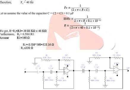
Figure 4. Fourth Order Low - Pass Butterworth Filter. High pass filter Design
The lower cut-off frequency is 40 Hz. Therefore, Fc = 40 Hz
Let us assume the value of the capacitor C = C2 = C3 = 0.1 F
We get, R=R2 3 3 .80 KΩ ≈ 40 K
Furthermore, Rf = 0.5861R1 Assume 1 560 Ω
Rf 0.586*560 328.16 Ω Rf ≈330 Ω
Figure 5. Fourth order High–pass Butterworth filter.
Notch filter
An EMG amplifier can “catch” ground noise from the power line which results in increased baseline noise (50/60 Hz noise).Notch filter is commonly used for the rejection of the single frequency such as 50 Hz power line frequency hum. The most commonly used notch filter is the twin-T network. This is a passive filter composed of two T-shaped networks. One T-Shape network is made up of two resistors and a capacitor, while the other uses two capacitors and a resistor. The notch out frequency is frequency at which maximum attenuation occurs, it is given by
Assume C=1 F,
IJEDR1403083
International Journal of Engineering Development and Research (www.ijedr.org)3328
Figure 6. 50 Hz Notch filter.Differential Amplifier
Raw EMG signal contains noise and its amplitude is in microvolt range. At the pre amplifier stage we had set limited gain as signal contains noise so we need further amplification of filtered signal. So output of the notch filter is given to differential amplifier. The gain of this differential amplifier is set 50.At this stage total amplification becomes 7909 means approximate ly 8000(25(instrumentation amplifier gain)*1.586(2nd order low pass filter gain)*1.586(2nd order low pass filter gain)*1.586(2nd order high pass filter gain)*1.586(2nd order high pass filter gain)*50(Differential amplifier gain)).
Figure 7. Non Inverting Differential Amplifier.
Full Wave Rectifier
In a rectification stage all negative amplitudes are converted to positive amplitudes, the negative spikes are “moved up” to plus or reflected by the baseline. It is useful for taking the absolute value of the raw signal mainly used as an intermediate step before another process (e.g., averaging, linear envelope and integration) can be done electronically and in real-time. Here bridge rectifier is use to rectify raw EMG signal. Diode 1N4148 is used for this purpose.
Figure 8. Full Wave Bridge Rectifier.
Envelope circuit
IJEDR1403083
International Journal of Engineering Development and Research (www.ijedr.org)3329
obtain patterns but it becomes difficult to detect artifacts. Enveloped signal is very useful as a control (myoelectric) signal.Figure 9. Enveloping Circuit.
Comparator
A comparator compares a signal voltage applied at the input of an op-amp with a known reference DC voltage V ref given at the other input. It is an open-loop operation, i.e., there is no feedback path in the case of a comparator. Comparators can be classified into two types, namely non-inverting and inverting. Here Inverting comparator is used.
The signal input is given to the inverting input terminal and the reference voltage is given to the non-inverting input terminal. When the input voltage is greater than the reference voltage that time output of the comparator goes negative Vsat pulse. When input signal is less than V ref output becomes positive Vsat. Here we set reference voltage according to our EMG signal amplitude.
Figure 10. Comparator Circuit.
Micro-controller
A Micro controller is simply a “Computer on a Chip”. ATMEGA16 single-chip serves as the microcontroller of the system; it accepts the digitized EMG signals and is programmed to control the R/C servomotor. The use of micro controller in the proposed design is to distinguish the different signals results from the different movements of the limb. We make use of the microcontroller in our design because of advantages of microcontroller from our prospective as follow:
Programming is Easy and can be used for multipurpose use.
Classification of the signals for different movement control can be implemented easily and it can also be used to control the prosthesis via the servo motor.
The Product is of a small size so consumes less space.
The prosthetic device used is not only function well but also cosmetically good and consume less weight with less space. So this advantage makes the design more stressful.
The system designed with very little effort and is easy to troubleshoot and maintain.
Motor Driver IC L298
The L298 is an integrated monolithic circuit in a 15- lead Multi watt and PowerSO20 packages. It is a high voltage, high current dual full-bridge driver designed to accept standard TTL logic levels and drive inductive loads such as relays, solenoids, DC and stepping motors. Two enable inputs are provided to enable or disable the device independently of the input signals. The emitters of the lower transistors of each bridge are connected together and the corresponding external terminal can be used for the connection of an external sensing resistor. An additional supply input is provided so that the logic works at a lower voltage.
Mechanical design
IJEDR1403083
International Journal of Engineering Development and Research (www.ijedr.org)3330
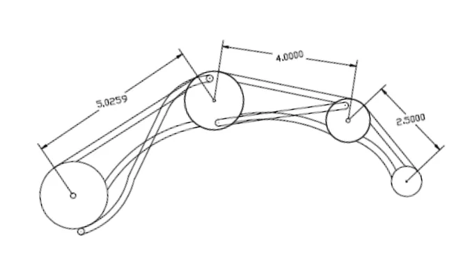
Figure 11. One Finger Design.Finger Linkage Design
One single finger was the starting point for the entire design process. The human hand was studied visually while grasping and handling many different objects. Being that the hand consists of four similar fingers and one thumb, it was logical to conclude that the finger design could potentially be replicated four times. This meant that if the size and space requirements to actuate one individual finger proved too large, then another method would be needed. The finger design process began with determining what motion was required for each finger. The human hand was simply viewed gripping various household objects such as a cup and marker commonly found in a person’s daily routine. The location of the various joints were measured and translated to drawings. The human finger is an amazing piece of engineering consisting of three individual pivot joints which can almost be individually actuated through muscular tendons. The four main fingers can also be spread apart sideways and rolled slightly culminating in an impressively large amount of total degrees of freedom. Fortunately, to perform the majority of common gripping tasks, only a small amount of motion should actually be required. The human finger achieves a conformal adaptive grip by bending the knuckles as an object is grasped.
Simple mechanical linkages are incredibly robust and reliable if they can be designed into the system. One link can act under both tension and compression, allowing for active force to be applied during both the closing and opening of a joint. There is no complicated procedure for installing or maintaining a linkage system.
IJEDR1403083
International Journal of Engineering Development and Research (www.ijedr.org)3331
Program Flow ChartFigure 12. Flowchart. V. RESULTS
EMG Acquisition Results
In our research EMG is generally acquired in range resulting between 20Hz to 120Hz.
Bandpass filter range is 40Hz to 1 KHz but practically it works nearly from 18Hz to 1.8 KHz.
Notch filter practically works in range of 48Hz to 53Hz.
After filtering EMG signal amplitude is between 300 to 500 mV.
After amplification EMG signal amplitude is between 3 to 5 V.
After rectification EMG signal amplitude is between 0.1 to 1.2 V.
Final EMG signal amplitude is between 2.3 to 4 V.
Comparator is set on 2 V.
EMG signals after filtering Pre-amplifier gain = 50
Bandpass filter range = 20Hz – 1.8 KHz Notch filter = 50Hz
Figure 13. Recorded EMG signals after filtering.
EMG signals after filtering with amplification Pre-amplifier gain = 50
Bandpass filter range = 20Hz – 1.8 KHz Notch filter = 50Hz
Amplifier gain = 100
Start
ADC of Raw EMG Signal
ADC
>1
Movement of
ARM
YES
IJEDR1403083
International Journal of Engineering Development and Research (www.ijedr.org)3332
Figure 14. Recorded EMG signals after filtering with amplification.EMG signals after Rectification
Figure 15. Rectified result of filtered and amplified EMG signals.
EMG signals after Enveloping
Figure 16. Enveloped EMG signals.
FFT of EMG signals during Fingers open-close movements in LabVIEW
IJEDR1403083
International Journal of Engineering Development and Research (www.ijedr.org)3333
FFT of EMG signals during hand continually closed movement in LabVIEWFigure 18. LabVIEW representation of EMG signals during continually closed hand. VI. CONCLUSION
We acquired EMG signals of finger gripping movements by placing surface electrodes at specific site on wrist. This was done by designing an EMG acquisition circuit which also include amplification and filtering of the acquired raw EMG signals. Then, we designed our own mechanical arm prototype which can give different movements of fingers through DC gear motors (each for individual fingers) attached. Different finger movements are controlled and driven using microcontroller ATMEGA16 and motor driver IC L298 respectively. All these processes are done on the bases of acquired and filtered EMG signals of an amputee from prior said EMG circuit. Whole EMG circuit was built using self-developed algorithm. Hence, one can see a better future for amputees by installing this type of myoelectric arm which is comparatively affordable in price into their handicapped area.
VII. ACKNOWLEDGMENT
This work has been supported by Government Engineering College Gandhinagar, Department of Bio-Medical Engineering. REFERENCES
[1] http://cdn.intechopen.com/pdfs-wm/40131.pdf
[2] ichard F. ff. Weir, Ph.D., “Design of artificial arms and hands for prosthetic applications”
[3] Chandrashekhar P. Shinde, “Design of Myoelectric Prosthetic Arm”, IJSET, ISSN 231 -5924 Volume 1, Issue 1, 2012, pp 21-25.
[4] “DELSYS” “Fundamental concepts in EMG Signal Acquisition” by Gianluca De Luca Rev.2.1, March 2003.
[5] B. Hudgins, P. A. Parker, and . N. Scott, “A new strategy for multifunction myoelectric control,” IEEE Transl. J. Biomed. Eng., vol.40, no. 1, pp. 82–94, Jan. 93.
[6] “Motion analysis of arm by use of myoelectric signal”, Eura, M.; Harada, H.; Ohbuchi, Y.; Yamaguchi, T. ICCAS-SICE, 2009, Publication Year: 2009, Page(s): 2023 – 2027.
[7] J. G. Webster, “Medical Instrumentation: Application and Design”, 3rd. New York: Wiley, 98, pp. 121–182.
[8] Selection of sampling rate for EMG pattern recognition based prosthesis control Guanglin Li ; Yaonan Li ; Zhiyong Zhang ; Yanjuan Geng ; Rui Zhou Engineering in Medicine and Biology Society (EMBC), 2010 Annual International Conference of the IEEE DOI: 10.1109/IEMBS.2010.5626224 Publication Year: 2010 , Page(s): 5058 – 5061.
[9] http://biomed.brown.edu/Courses/BI108/BI108_2003_Groups/Hand_Prosthetics/stats.html
[10]S. Franco, “Design With Operational Amplifiers and Analog Integrated Circuits”. New York: McGraw Hill, 1988. [11]W. Ganong, “Review of Medical Physiology”, 20th Ed. New York: McGraw Hill, 2001, pp. 72–74.