http://www.3com.com/
NBX
®Administrator’s Guide
Release 4.3
■ SuperStack 3 NBX ■ NBX 100
3Com Corporation reserves the right to revise this documentation and to make changes in content from time to time without obligation on the part of 3Com Corporation to provide notification of such revision or change. 3Com Corporation provides this documentation without warranty, term, or condition of any kind, either implied or expressed, including, but not limited to, the implied warranties, terms, or conditions of merchantability, satisfactory quality, and fitness for a particular purpose. 3Com may make improvements or changes in the product(s) and/or the program(s) described in this documentation at any time.
If there is any software on removable media described in this documentation, it is furnished under a license agreement included with the product as a separate document, in the hardcopy documentation, or on the removable media in a directory file named LICENSE.TXT or !LICENSE.TXT. If you are unable to locate a copy, please contact 3Com and a copy will be provided to you.
UNITED STATES GOVERNMENT LEGEND
If you are a United States government agency, then this documentation and the software described herein are provided to you subject to the following:
All technical data and computer software are commercial in nature and developed solely at private expense. Software is delivered as “Commercial Computer Software” as defined in DFARS 252.227-7014 (June 1995) or as a “commercial item” as defined in FAR 2.101(a) and as such is provided with only such rights as are provided in 3Com’s standard commercial license for the Software. Technical data is provided with limited rights only as provided in DFAR 252.227-7015 (Nov 1995) or FAR 52.227-14 (June 1987), whichever is applicable. You agree not to remove or deface any portion of any legend provided on any licensed program or documentation contained in, or delivered to you in conjunction with, this guide.
Unless otherwise indicated, 3Com registered trademarks are registered in the United States and may or may not be registered in other countries.
3Com, NBX, the 3Com logo, and SuperStack are registered trademarks of 3Com Corporation. NBX NetSet and pcXset are trademarks of 3Com Corporation.
Adobe is a trademark and Adobe Acrobat is a registered trademark of Adobe Systems Incorporated. InstallShield is a registered trademark of InstallShield Software Corporation. 5ESS is a registered trademark and 4ESS is a trademark of Lucent Technologies. Microsoft, Windows, Windows 2000, and Windows NT are registered trademarks of Microsoft Corporation.
C
ONTENTS
A
BOUTT
HISG
UIDE How to Use This Guide 15 Conventions 16International Terminology 16 Your Comments 17
1
I
NTRODUCTIONNetwork-based Telephony 19 Overview of the System Software 20
Auto Attendant 20
Auto Discovery and Auto Relocation 20 Virtual Tie Lines 20
Integrated Voice Mail and Messaging Features 20 Redialing From Call Logs 21
Call Recording 21
NBX NetSet Administration Utility 22 NBX NetSet Features 23
2
D
IALP
LANDial Plan Concepts and Overview 28 Call Process Flow 29
Inbound and Outbound Call Processing 29 NBX System Database 30
Dial Plan Tables 33
Dial Plan Command Format 34 Internal Dial Plan Table 38 Incoming Dial Plan Table 38
Least Cost Routing Dial Plan Table 39 Adding New Dial Plan Tables 40 Dial Plan Pretranslators 40
Pretranslators for Incoming Calls 41
Pretranslators for Certain Outgoing Calls 42 Managing the Dial Plan Configuration File 44
Accessing the Dial Plan 44
Creating Dial Plan Configuration Files 44
Importing and Exporting Dial Plan Configuration Files 45 Importing a User-Defined Dial Plan 47
Exporting (Saving) a Dial Plan Configuration File 48 Testing a Dial Plan 49
Generating a Dial Plan Report 50
Modifying a Dial Plan Configuration File 51 Outdialing Prefix Settings 52
Managing Extensions 52
Extension Settings Overview 52
Changing Extension Length and Ranges 56 How Auto Discovery Assigns Extensions 56 Modifying Extensions 57
Managing Extension Lists 59 Adding an Extension List 60 Modifying an Extension List 61 Removing an Extension List 62 Managing Dial Plan Tables 63
Determining Which Devices Use Dial Plan Tables 63 Removing a Dial Plan Table 64
Managing Dial Plan Pretranslators 64
Identifying Devices Using Pretranslators 65 Creating a Pretranslator for VTL Calls 65
Configuring the Dial Plan for the 4ESS Protocol (T1) 69 Overview of Voice Profile for Internet Mail 70
Configuring the Dial Plan for VPIM 71 Configuring VPIM Parameters 74
VPIM Control Parameters 74 Operations Management 74 Statistics 76
Advanced Settings 77
Configuring Domain Name Server Information 80 Overview of Virtual Tie Lines 80
VTL Connections Using Unique Extension Ranges 81 VTL Connections Using Site Codes 82
Conference Calls Using VTL Connections 83 How to Configure a Virtual Tie Line 84
License Installation 84 Dial Plan Configuration 85 Updating the Extension List 88
Adding VTL Devices to the Pretranslators (Optional) 89 Verification of the Virtual Tie Line 90
Call Rerouting for Virtual Tie Lines 94 Example Dial Plan Entries 94 Managing Existing Virtual Tie Lines 96
Modifying a Virtual Tie Line Name 96
Viewing and Resetting Virtual Tie Line Statistics 97 Enabling Audio Compression for VTL Calls 98 Enabling Silence Suppression on VTL Calls 98 Using a VTL Password 99
Configuring a VTL Password 99
Configuring VTL Passwords in the Dial Plan 100 Toll Calls Without a VTL Password 103
Music On Hold 103
Troubleshooting VTL Calls 103
Dial Plan Configuration File Commands 105 Dial Plan Command Summary 105 List of Dial Plan Commands 107
Adding a New Telephone 130 Modifying a Telephone 132 Checking a Telephone’s Status 132 Removing a Telephone 132 Rebooting a Telephone 132 Adding a Remote Telephone 133
Remote NAPT Device Configuration 133 Creating and Managing Bridged Extensions 134
Example Bridged Extensions Configurations 136 Defining Bridged Extensions 137
Defining Bridged Extensions on a Primary Telephone 137 Defining Bridged Extensions on a Secondary Telephone 138 Modifying Bridged Extensions 139
Sample Calling Situations Using Bridged Extensions 139 Viewing Bridged Extension Information 141
Creating and Managing Telephone Groups 142 Creating a New Telephone Group 142 Modifying a Telephone Group 142 Removing a Telephone Group 143
Viewing Telephone Group Membership 143 Recording and Monitoring Telephone Calls 144
Recording Calls Between Telephones with Different Recording Settings 144
Remote Telephones 145 Music On Hold 145 Non-NBX Telephones 145
Creating and Managing Button Mappings 146 Mapping Access Buttons 146
Mappings for Users and Groups 147
Creating a Busy Lamp/Speed Dial Button Mapping 148 Creating a Delayed Ringing Pattern 148
Creating Groups and Button Mappings 149 Changing Device IP Settings 150
Configuring Call Park 152
Changing the Name of a Call Park Extension 152 Removing a Call Park Extension 153
Configuring the NBX Attendant Console 153 Adding an Attendant Console 154 Modifying an Attendant Console 154 Viewing Attendant Console Status 154 Removing an Attendant Console 155 Configuring Attendant Console Buttons 155 Changing Attendant Console IP Settings 156 Configuring and Managing Analog Line Card Ports 156
Configuring a Line Card Port 157 Modifying a Line Card Port 160 Removing a Line Card Port 160 Verifying Line Card Port Status 161 Rebooting a Line Card Port 161 Advanced Settings 161
Connecting and Managing Analog Devices 162 Adding an Analog Terminal Card 162
Adding an Analog Terminal Adapter (ATA) 164 Modifying an Analog Terminal Port 165 Removing an Analog Terminal Adapter 165
Viewing The Status of an Analog Terminal Adapter 165 Advanced Settings 166
Configuring and Managing BRI-ST Digital Line Cards 167 Adding an ISDN BRI-ST Digital Line Card 167
Configuring the BRI-ST Digital Line Card 170 BRI-ST Card Status Lights 172
Modifying a BRI-ST Card 173
Adding or Modifying a BRI Group 174 Modifying BRI Card Channels 176 Modifying IP Settings for a BRI Card 177 Removing a BRI Digital Line Card 178
Configuring and Managing E1 Digital Line Cards 179 Adding an E1 Digital Line Card 179
Configuring an E1 Digital Line Card 182 E1 Card Status Lights 184
Modifying an E1 Card 186
Configuring and Managing T1 Digital Line Cards 194 Adding a T1 Digital Line Card 195
Configuring a T1 Digital Line Card for the DS1 Protocol 198 Configuring a T1 Digital Line Card for ISDN PRI Signaling 202 T1 Card Status Lights 206
Modifying a T1 Card 207
Support of AT&T’s 4ESS Switch Protocol 209 Modifying a T1 Group 212
Modifying T1 Card Channels 214 Modifying IP Settings for a T1 Card 216 Removing a T1 Digital Line Card 217
Setting Up a Digital Line Card at a Remote Location 217 Setting Up T1/E1 Logging 220
Viewing CSU State Information and Statistics 220 T1.231 Near End 221
T1.231 Far End 221 TR54016 Near End 221 TR54016 Far-End 221 G.826 Near End 222 G.826 Far End 222 Using Loopback Tests 222
Enabling or Disabling Loopback Tests 223
4
U
SERC
ONFIGURATION Users 225Phantom Mailboxes 225 Call Pickup 226
Group Numbers 226 TAPI Route Points 227
Redirect Behaviors 228
Viewing TAPI Route Point Statistics 230 Specifying TAPI Line Redirect Timeout 231 Hunt Groups 231
Hunt Group Considerations 232 Linear and Circular Hunt Groups 232 Calling Groups 233
Call Coverage 233 Class of Service (CoS) 233
5
S
YSTEMC
ONFIGURATION System Settings 235System-wide Settings 237 Audio Settings 240 Regional Settings 244 Date and Time 246 Timers 246
Ringing Patterns 247 Multicast Addresses 247 IP Addresses 249 Maintenance Alerts 249 Speed Dials 250
Business Identity 251 Business Information 251 Business Hours 251 System Mode 251 Security 252
TAPI Settings 253 Disk Mirroring 253
Voice Mail Extensions 262 Voice Mail Passwords 262
IMAP for Integrated Voice Mail 262 Off-Site Notification 264
Status 265 Port Usage 266 User Usage 267 Auto Attendant 268
Overview of Auto Attendant Features 268 Adding an Auto Attendant 270
Managing Auto Attendants 280 Voice Application Setup Utility 282 Testing the Auto Attendant 283 Voice Profile for Internet Mail 284
Control Parameters 285 Operations Management 285 Statistics 287
Advanced Settings 288
7
O
PERATIONSSoftware Upgrade 291
System Software Licensing 292 Restricted Operation 294 Considerations 294 Customer Service 295 Reboot/Shutdown 295 Manage Data 296
Backup 296 Restore 299
Convert Database 300 Purge Database 300
Licenses 301
Add a License 302 Remove a License 302 Usage Report 302 Backing Up Licenses 302
Restoring Backed-Up Licenses 302 Obtaining Details of License History 303 Regional Software 303
Install 303 Remove 303 Details 304
Third-Party Drivers 304
NBX Software Upgrades 305 Third-Party Telephone Groups 305
8
R
EPORTS Directory 307 Device List 308 System Data 308Disk Status 308
Power Supply Status 308 Call Reporting 309
Windows Environment Specifications 309 Installing Call Reports 310
Configuring Call Reporting 310 Purge CDR 310
9
D
OWNLOADSSoftware 311 LabelMaker 312
Using the Telephone Local User Interface Utility 316 Using H3PingIP 325
System-level Troubleshooting 326 Digital Line Card Troubleshooting 329 Alarm Conditions (Overview) 330 Alarm Descriptions 330
Alarms on NBX Digital Line Cards 331 Configuration and Status Reports 332 Connecting a Computer to a Serial Port 339 Servicing the Network Call Processor Battery 341 Getting Service and Support 341
A
I
NTEGRATINGT
HIRD-P
ARTYM
ESSAGINGInstalling Software on the Third-Party Messaging Server 343 Configuring the NBX System 343
Configuring NBXTSP on the Server 345
B
ISDN C
OMPLETIONC
AUSEC
ODESC
C
ONFIGURINGO
PTION184
ON AW
INDOWS2000 DHCP
S
ERVEROverview 353
Creating Option 184 354 Editing Option 184 Values 354 Activating Option 184 355
D
C
ONNEX
TIONSH.323 G
ATEWAY Overview of ConneXtions 358 Installation Requirements 358Windows-based System 359 ConneXtions Software 362 Preparing for Installation 362
Assembling System Information 362 Verifying the G.723 Converter 363
Checking Service Pack (Windows NT Only) 363 Configuring Licenses 363
Installing ConneXtions 365 Finishing the Installation 367 Overview of H.323 368
Negotiated Connections 368 Negotiated Voice Compression 369 Standard Extensions 370
Remote Internet Device Connections 370 The H.323 Connection 371
Connection Considerations 372 Overall Connectivity 372 Quality of Service 373
Quality of Service Control 376 Special Issues 378
Firewall Security 378 Gateway Load 380 Remote Access 380 PBX Connections 381 Class of Service 384
IP Type of Service and Differentiated Services 384 Alternate Gatekeepers 384
Checking Connections 384 Gateway Checks 385 Network Checks 385 Placing Calls 389
IP Address Entry 389 Speed Dials 391 One Button Access 392
Entering Digits During Calls 393 Receiving Calls 393
Related H.323 Documentation 396
E
C
ALLERID
Forwarded Calls and Caller ID 397 Long Caller ID Character Strings 397 Specific Caller ID Situations 398
Analog Telephones 398
Bridged Extension Telephones 399
Calls That Are Forwarded Multiple Times 399 External Calls 399
Internal Calls 401 Nortel Phones 401 Parked Calls 401
Second Incoming Call 401 TAPI Calls 401
TAPI Redirected Calls 401 VTL Calls 401
Calls Transferred to Hunt Groups 401
G
LOSSARYI
NDEXFCC C
LASSA V
ERIFICATIONS
TATEMENTI
NDUSTRYC
ANADAN
OTICEA
BOUT
T
HIS
G
UIDE
This guide describes how to configure and manage the SuperStack® 3
NBX® and the NBX®100 Networked Telephony Solutions. For
information about installing either system for the first time, see the NBX Installation Guide.
If the information in the release notes differs from the information in this guide, follow the instructions in the release notes. Release notes are available on the NBX Resource Pack CD and the 3Com Partner Access Web Site.
How to Use
This Guide
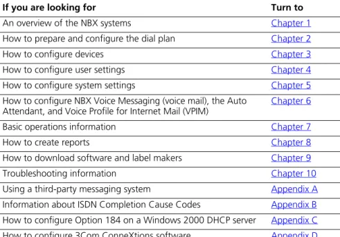
Table 1 can help you find information in this guide.
Table 1 Overview of This Guide
If you are looking for Turn to
An overview of the NBX systems Chapter 1
How to prepare and configure the dial plan Chapter 2
How to configure devices Chapter 3
How to configure user settings Chapter 4
How to configure system settings Chapter 5
How to configure NBX Voice Messaging (voice mail), the Auto Attendant, and Voice Profile for Internet Mail (VPIM)
Chapter 6
Basic operations information Chapter 7
How to create reports Chapter 8
How to download software and label makers Chapter 9
Troubleshooting information Chapter 10
Using a third-party messaging system Appendix A
Information about ISDN Completion Cause Codes Appendix B
How to configure Option 184 on a Windows 2000 DHCP server Appendix C
Conventions
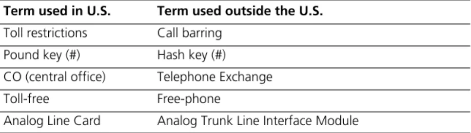
Table 2 lists conventions that are used throughout this guide.International
Terminology
Table 3 lists the United States and international equivalents of some of the specialized terms that are used in the NBX documentation.
Caller ID behavior Appendix E
Definitions of telephony and networking terms Glossary
References to all topics in this book Index
FCC and Industry Canada information, Software End-User License Agreement, and Limited Warranty for Software and Hardware
End of the book Table 1 Overview of This Guide
If you are looking for Turn to
Table 2 Notice Icons
Icon Notice Type Description
Information note Information that describes important features or instructions.
Caution Information that alerts you to potential loss of data or potential damage to an application, device, system, or network.
Warning Information that alerts you to potential personal injury.
Table 3 International Terminology
Term used in U.S. Term used outside the U.S.
Toll restrictions Call barring
Pound key (#) Hash key (#)
CO (central office) Telephone Exchange
Toll-free Free-phone
Your Comments 17
Your Comments
Your suggestions are important to us. They help us to make the NBX documentation more useful to you.Send comments about this guide or any of the 3Com NBX documentation and Help systems to:
[email protected]
Please include the following information with your comments:
■ Document title
■ Document part number (found on the front page) ■ Page number
Example:
NBX Administrator’s Guide
Part Number 900-0156-01 Rev AA
Page 25
1
I
NTRODUCTION
The NBX Administrator’s Guide explains how to configure your NBX® system. This chapter covers these topics:
■ Network-based Telephony ■ Overview of the System Software ■ NBX NetSet Administration Utility ■ NBX NetSet Features
For information about installing hardware components, see the NBX Installation Guide.
Network-based
Telephony
3Com Networked Telephony Solutions merge telephony with networking by delivering business telephone service over a data network.
To a telephone user, an NBX Telephone is an office telephone. You can use it to make and receive calls, transfer calls, park calls, use voice mail, and so on. Inside, the NBX Telephone is a network device that can communicate over the LAN using Ethernet frames or IP packets. The telephone also includes a LAN port. You can connect your computer to your network through the telephone and avoid the need for a second LAN connection at the desktop.
The core of 3Com Networked Telephony Solutions is the Network Call Processor (NCP). The NCP manages the processes of making and receiving calls, providing voice mail and auto attendant services, and responding to requests for special services, such as access to the NBX NetSet administration utility, Computer Telephony Integration (CTI) services, or the system’s IMAP (Internet Message Access Protocol) server.
the processing required to connect two telephones, the telephones communicate directly with each other. Therefore, existing conversations are not affected if power to the NCP fails.
Overview of the
System Software
This section describes the major features of the NBX system.
Auto Attendant With the Auto Attendant, a full-featured call answering service, you set up automated call answering, including multiple Auto Attendants, each with separate menu structures, to manage incoming calls.
Auto Discovery and Auto Relocation
The Network Call Processor and the NBX Telephones communicate with each other to streamline configuration. When you connect a new telephone, the system discovers it and adds it to the configuration database. The communication between devices means that if telephone users move their telephones to a new location, the telephones retain their extension number and personal settings. You do not have to change telephone addresses and data for them.
Virtual Tie Lines You can connect two or more NBX systems that are connected to your Wide Area Network. Calls made over Virtual Tie Lines incur no toll charges. G.729 compression allows you to make the most of your bandwidth.
Integrated Voice Mail and Messaging Features
NBX Voice Messaging is a standard feature of the 3Com Networked Telephony Solution. Voice Messaging supports Off-Site Notification, which alerts you if you receive new voice messages when you are out of the office. Voice Messaging also includes an IMAP (Internet Message Access Protocol) mail server that allows you to retrieve voice mail messages through any IMAP4-compatible e-mail client.
Standard NBX Telephone Features
Overview of the System Software 21
Redialing From Call Logs
In an NBX Telephone display panel, you can view logs of recent Missed Calls, Answered Calls, and Dialed Calls. You can select and redial a call from any of these lists, as well as from the directory of internal users, your personal speed dial list, or the system-wide speed dial list.
Calling Line Identity Restriction (CLIR)
When an NBX Telephone user makes a call on an ISDN channel, the receiving party can see the identity of the caller (normal ISDN behavior). When the NBX option Calling Line Identity Restriction (CLIR) is enabled, the receiving party cannot see your identity when you call.
Computer Telephony Integration (CTI) Connectivity
3Com Networked Telephony Solutions provide a software-based CTI solution through the Microsoft Telephony Applications Programming Interface (TAPI). Your telephone and your computer connect to the same LAN so that your computer does not need any special hardware, such as proprietary cards. The NBX system works with TAPI 2.X-compliant CTI applications.
Call Recording You can integrate a third-party call recording system into your NBX system so that selected calls can be recorded. (Optional license required.)
NBX Call Reports NBX Call Reports, a Windows client program, is a standard feature of 3Com Networked Telephony Solutions. Call Reports allows you to save calling data about inbound and outbound calls, present it in a report, or export it to spreadsheets, word processors, or reporting programs.
NBX Resource Pack CD
3Com Networked Telephony Solutions include the NBX Resource Pack CD with the most recent system software for backup and upgrade purposes, optional software, and electronic versions of system documentation.
Support for Multiple Languages
NBX NetSet
Administration
Utility
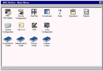
The NBX NetSet utility is a web interface in which you configure and manage the NBX system. You need Microsoft Internet Explorer (version 5.5 or later is optimal) to administer the system. You do not need Internet access to use the NBX NetSet utility.
Figure 1 shows the NBX NetSet - Main Menu window, which appears when you log on to the NBX NetSet utility.
Figure 1 NBX NetSet - Main Menu Window
NBX systems present the NBX NetSet utility through an embedded web server that is integrated in system software. NBX NetSet passwords grant system administrators and users different levels of access privileges.
Individual telephone users can view or change their personal settings such as personal speed dial lists, off-site notification settings, and ringing tones.
NBX NetSet Features 23
NBX NetSet
Features
Table 4 describes the features that administrators can access through the NBX NetSet - Main Menu window.
Table 4 NBX NetSet Features for the NBX Administrator
Icon Description
Configure and manage system-wide NBX Voice Messaging, Auto Attendants, and VPIM settings. If you install a license for a third-party messaging application and disable NBX Messaging, this icon is not available.
Configure and manage NBX devices, such as:
■ Telephones and telephone groups ■ Analog Line Cards
■ Digital Line Cards (T1, E1, and BRI-ST cards) ■ Analog Terminal Adapters (ATAs)
■ Call Park
■ Attendant Consoles ■ Virtual Tie Lines
Configure and manage your system Dial Plan.
Download, install, configure, and manage additional system features, such as:
■ Optional NBX software, such as NBX Call Reports and TAPI software ■ LabelMaker utility for telephones and NBX Attendant Consoles ■ Quick Reference Guides for the NBX Business and Basic Telephones,
and analog telephones on the NBX system
■ NBX manuals including the NBX Installation Guide, NBX
Configure and manage these system-level operations:
■ Upgrading software
■ Rebooting and shutting down the NBX system ■ Managing data (backup and restore)
■ Viewing and managing event log files
■ Viewing and adding licenses for optional features
■ Setting regionally different information (voice-prompt language, dial
tones and cadences, and documentation language)
■ Installing third-party drivers (for example, for telephones other than
NBX Telephones)
View and manage system reports:
■ Directory lists of users ■ Device List
■ System Data ■ Call Reporting
Configure and manage the system-level settings for:
■ System Settings
■ Audio Settings including compression and silence suppression ■ System-wide Speed Dials
■ Business Identity ■ Security ■ TAPI Settings
Configure settings for TAPI (Telephony Applications Programming Interface). (Can also be configured from the System Configuration icon.)
Configure and manage:
■ Users
■ Call Pickup Groups ■ TAPI Route Points ■ Hunt Groups
■ Class of Service (CoS) Settings for users
Table 4 NBX NetSet Features for the NBX Administrator (continued)
NBX NetSet Features 25
Table 5 describes the additional icons that appear on or below the NBX NetSet - Main Menu window. They are shortcuts to specific areas within the NBX NetSet utility and to some of the online documentation.
Table 5 NBX NetSet Shortcuts
Icon Description
The Help icon in the NBX NetSet - Main Menu window provides access to the Contents, Index, and search features of the online Help system. The Help icon on individual dialog boxes takes you directly to
content-specific Help in addition to accessing the global Help features.
Displays Tab To It, a window that shows all the tabs for the entire system. Click on a tab in the Tab to It window to go directly to that tab’s interface. The Tab To It icon also appears on most dialog boxes throughout the NBX NetSet utility.
If you install a license for a third-party messaging application, the tab for NBX Messaging is disabled in the Tab To It window
Opens the online (PDF) version of the NBX Installation Guide. This icon is available in the NBX NetSet - Main Menu window only.
Opens the online (PDF) version of the NBX Administrator’s Guide (this book). This icon is available in the NBX NetSet - Main Menu window only.
Opens the online (PDF) version of the NBX Telephone Guide. This icon is available in the NBX NetSet - Main Menu window, and below the User Settings window when users log on to the NBX system.
Opens the online (PDF) version of the NBX Feature Codes Guide. This icon is available in the NBX NetSet - Main Menu window, and in the User Settings window when users log on to the NBX system.
2
D
IAL
P
LAN
The NBX system’s dial plan determines how the system handles calls. It defines the set of destinations that the system can reach, how to get to these destinations, and which telephone numbers to dial to reach these destinations. This chapter provides information about understanding, developing, and managing the dial plan. It covers these topics:
■ Dial Plan Concepts and Overview ■ Dial Plan Tables
■ Dial Plan Pretranslators
■ Managing the Dial Plan Configuration File ■ Outdialing Prefix Settings
■ Managing Extensions ■ Managing Extension Lists ■ Managing Dial Plan Tables ■ Managing Dial Plan Pretranslators
■ Configuring the Dial Plan for the 4ESS Protocol (T1) ■ Overview of Voice Profile for Internet Mail
■ Configuring the Dial Plan for VPIM ■ Configuring VPIM Parameters ■ Overview of Virtual Tie Lines ■ How to Configure a Virtual Tie Line ■ Call Rerouting for Virtual Tie Lines ■ Managing Existing Virtual Tie Lines ■ Using a VTL Password
■ Dial Plan Configuration File Commands
Dial Plan Concepts
and Overview
The dial plan configuration file is an ASCII text file that implements the dial plan and specifies pretranslation (digit manipulation). The system is shipped with several default dial plan configuration files, typically, a 3-digit and a 4-digit file for each supported country.
The dial plan configuration file includes several tables:
■ Internal — Must be table ID 1 ■ Incoming — Must be table ID 2
■ Least Cost Routing — Must be table ID 3 ■ Routes
■ Pretranslators
You can create additional tables if necessary.
Each dial plan table consists of a series of entries, each of which includes a sequence of digits and the action to be performed by the NBX system in response to sending or receiving those digits. For more information on the Internal, Incoming, and Least Cost Routing dial plan tables, see “Dial Plan Tables” on page 33.
Usually, you access the dial plan configuration file and manage dial plan operations, tables, pretranslators, and extension lists through the NBX NetSet administration utility. If your dial plan is larger than 32,000 characters, however, you cannot edit the dial plan using the NBX NetSet utility. You must export the dial plan, edit it, and then import it.
Before you configure the dial plan, please be sure that you understand these concepts:
■ Call Process Flow (page 29)
■ Inbound and Outbound Call Processing (page 29) ■ NBX System Database (page 30)
■ NBX System Dial Plan (page 30) ■ Pretranslation (page 31)
■ Routing (page 31)
Dial Plan Concepts and Overview 29
Call Process Flow The dial plan configuration file is a key component of inbound and outbound call processing. The dial plan tables in the configuration file process incoming calls in this order:
1 Incoming Dial Plan Table
2 Pretranslator Table
The dial plan tables process outgoing calls in this order:
1 Internal Dial Plan Table
2 Least Cost Routing Table
After pretranslation (if performed), the final translation process routes the call to the destination.
Inbound and Outbound Call Processing
The system routes all inbound and outbound calls through the dial plan.
Inbound Call Processing
The system processes inbound calls using the Incoming table. The system can also use pretranslators to perform digit manipulations on incoming calls before it uses the Incoming table.
Each pretranslator operation performs a digit manipulation operation on the dialed digits. For incoming calls, if the DID/DDI range matches the internal extensions, the dial plan requires no pretranslator. However, you can use pretranslators to map nonmatching dialed numbers on an incoming DID/DDI channel to desired internal extensions. See the
example in Customer Requirement 1 in “Sample Solutions Using Dial Plan Configuration File Commands” on page 120.
Outbound Call Processing
The system processes outbound calls using the Internal dial plan table or the Least Cost Routing table.
You can add entries to the Internal dial plan table to match the system to your service. See Customer Requirement 2 in “Sample Solutions Using Dial Plan Configuration File Commands” on page 120.
entries. For more information, see TimedRoute Create, TimedRouteEntry Create, and TimedRouteOperation Create later in this chapter.
NBX System Database The NBX system database contains a default dial plan that is initially loaded at the factory and is reloaded if you purge the database. The default dial plan for the SuperStack 3 NBX system is a 4-digit plan; for the NBX 100, it is a 3-digit plan.
Changes that you make to any system settings, including changes made by importing a modified dial plan configuration file, are stored in the database. When you reboot the system, it loads the database with any changes that you have made. The NBX system database includes all of the settings necessary for system operation.
NBX System Dial Plan You can import a dial plan configuration file to provide the system with a set of operating instructions for managing the telephone system.
Alternatively, if you have made changes to the currently loaded
instructions through the NBX NetSet utility, you can export the dial plan configuration file to save it. You can also make changes by editing the configuration file off-system, using any ASCII editor, and then importing the modified file. You can easily reuse a given configuration file on many systems. For more information, see “Importing and Exporting Dial Plan Configuration Files” on page 45.
The system is shipped with several default dial plan configuration files, typically, a 3-digit and a 4-digit file for each country that is supported. In addition, the file samples.txt contains several examples that illustrate
how you can configure the dial plan configuration file to control how the system manages incoming and outgoing calls.
Normally, you completely configure a dial plan before you start to use the system to control the telephones. Although you can make changes later, major changes in the dial plan can disrupt the system.
Decide whether you want to use a 3-digit or 4-digit dial plan before you create the dial plan, autodiscover, or manually add telephones or other devices to the NBX system.
Dial Plan Concepts and Overview 31
Rebooting the system disrupts service to the telephones. Plan to reboot at a time that does not inconvenience telephone users.
Pretranslation Pretranslation is the process of translating (or manipulating) dialed digits before they are passed to the appropriate dial plan table for subsequent routing. You can set the dial plan to perform pretranslation on incoming or outgoing calls. For more information, see “Dial Plan Pretranslators” on
page 40.
Routing Routing specifies how a call reaches a destination. You define the routes for the system to use in the Routes section of the dial plan configuration file.
When you define call routing, you can also instruct the system to perform pretranslations (digit manipulations). Both destination routes and timed routes have digit manipulation operations (append, prepend, replace, stripLead, or stripTrail).
The system passes dialed digits first through the device’s Least Cost Routing table (if there is one). If the system finds no entry there, it then uses the Normal dial plan table. If it does find an entry in the Least Cost Routing table, it attempts to use that entry and, even if the attempt is unsuccessful, it does not use the Normal table.
You can route incoming calls to the Auto Attendant port, and you can instruct the Auto Attendant to route these calls to any internal or external number.
CAUTION: If you configure the Auto Attendant so that it can access any external number, you risk the possibility of toll fraud. You can reduce the possibility of toll fraud by explicitly putting specific external numbers into the outgoing dial plan table. This precaution prevents outside callers from dialing any external number except the ones that you define.
There are two types of routes:
■ Destination routes — Specify the extension of a destination device.
They can also perform digit manipulation operations on the dialed digits that resulted in the selection of this route before those digits are dialed on the destination device.
■ Timed routes — Specify time of day and day of week criteria which,
CAUTION: If you operate the NBX system in Keyset Mode, routes are not applicable.
For more information, see “DestinationRoute Create”on page 107,
“TimedRoute Create”page 116, and related entries under “Dial Plan Configuration File Commands” on page 105.
System Features Affected by the Dial Plan Configuration
The dial plan configuration affects several system features:
■ Keyset Mode Operation Using the Dial Plan ■ Hybrid Mode Operation Using the Dial Plan ■ Off-Site Notification
Keyset Mode Operation Using the Dial Plan
If you map any telephone buttons that have LEDs to specific Analog Line Card ports, you enable Keyset mode in the NBX system. Instead of dialing a single digit (typically 8, 9, or 0) before placing an outside call, the user presses a button to select an available Analog Line Card port. The user defines the routing (that is, the selection of a destination device) by pressing the button to select the Analog Line Card port; however the NBX system controls the call using the dial plan.
You cannot map a digital line extension in Keyset mode.
The NBX system applies any Class of Service restrictions that are associated with the user's telephone to determine whether to make a call. The system also uses any pretranslator that a device uses and performs any required digit manipulation operations before it actually transmits the digits on the Analog Line Card or Digital Line Card port.
Hybrid Mode Operation Using the Dial Plan
If you map telephone buttons for some telephones but not others, you enable Hybrid mode (a mixture of standard and Keyset behaviors). The system provides a system-wide External Prefix setting, which allows the administrator to establish a prefix.
Off-Site Notification
Dial Plan Tables 33
Example: When voice mail arrives, the NBX system dials the telephone number of the user’s pager. Typically, you use a system-wide prefix to designate the device or devices you want to use for outdialing purposes, including off-site notification calls.
Example: If the user’s pager number is 800-555-3751, and the system-wide prefix digit is 9, the system dials 98005553751 to send a call to the user’s pager.
To tell the system to dial a single Line Card port or a restricted number of Line Card ports, create a suitable pool of Line Card ports for that purpose, and then use an existing set of dial plan table entries (such as the entries that begin with 8) or create a new set of entries to allow the dial plan devices to route calls via the selected line card ports.
Example: You set up one 4-port card to handle all off-site notification calls. You create a set of entries in the Internal dial plan table that each start with the digit 8. You define a route to the 4-port card for all of these dial plan entries so that whenever the system acts on one of these entries, it uses one of the 4 ports on that card to dial out and notify the user.
To apply different off-site CoS restrictions to different users, you need multiple dial plan entries. If you are not trying to apply the CoS restrictions, then a single dial plan entry is sufficient.
Dial Plan Tables
Dial plan tables contain information that controls how the system routes calls. Each dial plan configuration file consists of at least three dial plan tables. This section discusses these topics:■ Dial Plan Command Format
■ Internal Dial Plan Table — Must be table ID 1 ■ Incoming Dial Plan Table — Must be table ID 2
■ Least Cost Routing Dial Plan Table — Must be table ID 3 ■ Adding New Dial Plan Tables
CAUTION:Tables 1, 2, and 3 must exist. Do notdelete them. You may create additional dial plan tables if necessary, but they must be numbered 4 or higher.
find a corresponding entry in the Internal table. If you have entries for the same purpose in both the Least Cost and Internal tables, the behavior of the dial plan can be confusing.
See “Dial Plan Command Format” next for a description of dial plan command syntax and structure. For a complete list and description of dial plan commands, including command arguments and examples, see “Dial Plan Configuration File Commands” on page 105.
Dial Plan Command Format
Each dial plan table contains a sequence of commands. These commands collectively determine how calls are handled.
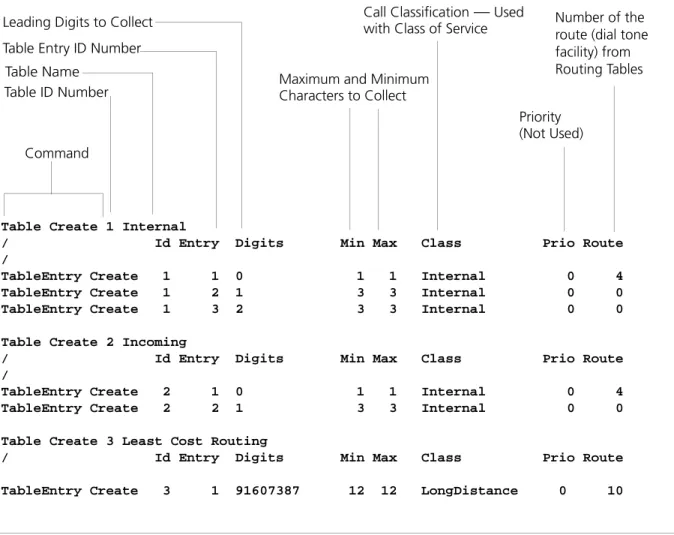
Most of the dial plan commands have a very similar format, as shown in
Dial Plan Tables 35
Figure 2 Dial Plan Command Format
Table 6 describes each field of a dial plan command.
Table Create 1 Internal
/ Id Entry Digits Min Max Class Prio Route /
TableEntry Create 1 1 0 1 1 Internal 0 4 TableEntry Create 1 2 1 3 3 Internal 0 0 TableEntry Create 1 3 2 3 3 Internal 0 0
Table Create 2 Incoming
/ Id Entry Digits Min Max Class Prio Route /
TableEntry Create 2 1 0 1 1 Internal 0 4 TableEntry Create 2 2 1 3 3 Internal 0 0
Table Create 3 Least Cost Routing
/ Id Entry Digits Min Max Class Prio Route
TableEntry Create 3 1 91607387 12 12 LongDistance 0 10
Command Table ID Number Leading Digits to Collect
Table Entry ID Number
Call Classification — Used with Class of Service
Priority (Not Used) Table Name
Number of the route (dial tone facility) from Routing Tables Maximum and Minimum
Characters to Collect
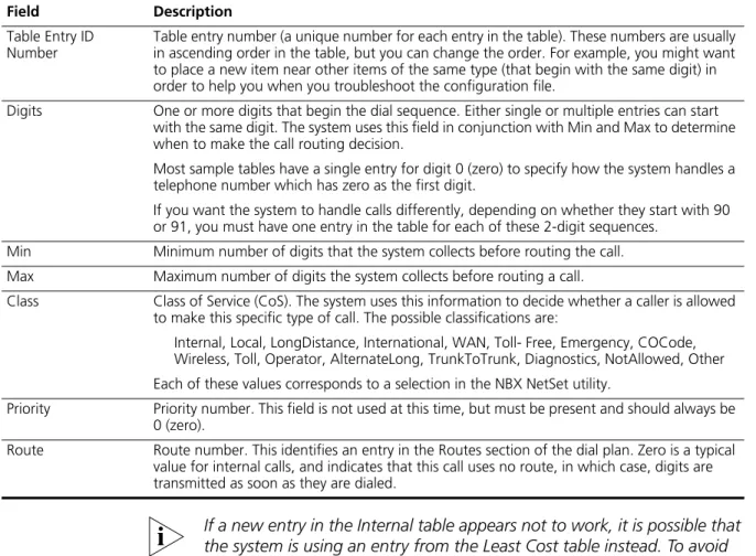
Table 6 Dial Plan Command Fields
Field Description
Command Command name. For example, TableEntry Create is the command that makes Class of Service and call routing decisions based on the correspondence of dialed digits and table entry digits. See “Dial Plan Configuration File Commands” later in this chapterfor a description of each command.
If a new entry in the Internal table appears not to work, it is possible that the system is using an entry from the Least Cost table instead. To avoid such conflicts, you can accomplish least cost routing using only the Internal table. 3Com strongly recommends that, to keep the dial plan as simple as possible, you use only the Internal table for least cost routing.
For more information on how to use the dial plan configuration file, see“Managing the Dial Plan Configuration File” on page 44.
Basic Dial Plan Table Examples
These examples describe the basic operation of a dial plan table.
Example: If you are using a 4-digit dial plan and the telephone
extensions start with 2, then the table entry with 2 in the Digits column typically has 4 in the Min column. Before making a decision, the system Table Entry ID
Number
Table entry number (a unique number for each entry in the table). These numbers are usually in ascending order in the table, but you can change the order. For example, you might want to place a new item near other items of the same type (that begin with the same digit) in order to help you when you troubleshoot the configuration file.
Digits One or more digits that begin the dial sequence. Either single or multiple entries can start with the same digit. The system uses this field in conjunction with Min and Max to determine when to make the call routing decision.
Most sample tables have a single entry for digit 0 (zero) to specify how the system handles a telephone number which has zero as the first digit.
If you want the system to handle calls differently, depending on whether they start with 90 or 91, you must have one entry in the table for each of these 2-digit sequences.
Min Minimum number of digits that the system collects before routing the call.
Max Maximum number of digits the system collects before routing a call.
Class Class of Service (CoS). The system uses this information to decide whether a caller is allowed to make this specific type of call. The possible classifications are:
Internal, Local, LongDistance, International, WAN, Toll- Free, Emergency, COCode, Wireless, Toll, Operator, AlternateLong, TrunkToTrunk, Diagnostics, NotAllowed, Other
Each of these values corresponds to a selection in the NBX NetSet utility.
Priority Priority number. This field is not used at this time, but must be present and should always be 0 (zero).
Route Route number. This identifies an entry in the Routes section of the dial plan. Zero is a typical value for internal calls, and indicates that this call uses no route, in which case, digits are transmitted as soon as they are dialed.
Table 6 Dial Plan Command Fields (continued)
Dial Plan Tables 37
would collect all 4 digits of the extension. If the caller dials fewer than the Min number of digits, the system times out in 20 seconds.
Example: If Digits = 2, Min = 4, and Max = 4, the system knows that if the first digit is 2, it must collect no less than 4 and no more than 4 digits before making the call routing decision.
If the caller dials at least the minimum number of digits and not more than the maximum number of digits, the system waits 5 seconds and then routes the call based on the digits dialed.If the caller dials more than the maximum number of digits, the system attempts to place the call.
Often, Max value and the Min value are identical, because you want the system to collect a specific number of digits, no more and no less.
Example: For internal extensions, you want the system to collect exactly 3 digits (4 in a 4-digit dial plan) before making a decision, so you would set both Min and Max to 3 (4 in a 4-digit dial plan).
The two columns may be different if the table entry applies to more than one situation.
Example: In the United States, the Min value for the 90 entry is 2, because 90 allows an internal caller to reach a telephone company operator (9 to get an outside line, and then 0 to get the operator). The Max value is 64, because the caller can continue to dial after the zero, entering a number to call, plus a telephone credit card number, and possibly an identification code number.
If the caller dials only 90 (which satisfies the minimum of two digits) and stops dialing, the system waits for 5 seconds. If no other digits are entered, the system connects the caller to the operator.
If other digits are dialed, the system accepts them up to the limit of 64. If the caller stops after dialing fewer than 64 digits, the system again waits 5 seconds before acting on the dialed sequence of digits.
Example: You can assign the company’s Vice President of Finance to a group that you name the All Privileges Group. You can set the
permissions for that group so that group members have permission to make LongDistance calls during all system modes.
Internal Dial Plan Table
The Internal dial plan table (table ID 1) defines how to handle calls placed from internal devices, such as NBX Business or Basic Telephones, to a destination. A destination can be another internal device, such as a local telephone, or an external telephone line (Analog Line Card or Digital Line Card) that connects the NBX system to other facilities.
The Internal dial plan table consists of a series of commands. For an example of the command format, see “Dial Plan Command Format”
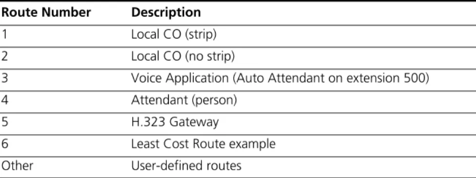
earlier in this chapter. Table 6 on page 35 describes each element of the command. Table 7 describes the predefined routes.
You cannot delete or modify predefined routes, only create new routes.
Each device must have a Normal table. The Least Cost Routing table is optional. Telephones use the Internal dial plan table (table ID 1) as their normal outbound table and the Least Cost Routing table (table ID 3) as their long distance routing table.
Incoming Dial Plan Table
The Incoming dial plan table (table ID 2) defines how calls arriving from outside the NBX system are routed to extensions. Incoming calls can arrive on analog telephone lines or through Digital Line Card ports.
The incoming dial plan table consists of a series of commands. For an example and basic understanding of the command format, see “Dial Plan
Table 7 Predefined Routes
Route Number Description
1 Local CO (strip)
2 Local CO (no strip)
3 Voice Application (Auto Attendant on extension 500)
4 Attendant (person)
5 H.323 Gateway
6 Least Cost Route example
Dial Plan Tables 39
Command Format” on page 34. For a description of the each element of a dial plan command, see Table 6 on page 35.
By default, Line Card ports, Digital Line Card ports, and H.323 gateways use the Incoming dial plan table as their normal dial plan table. An Incoming dial plan table typically has a more restricted list of dialable digits than the Internal dial plan table. You usually cannot dial extensions associated with internal paging or Analog or Digital Line Card ports.
Least Cost Routing Dial Plan Table
The Least Cost Routing table (table ID 3) defines how to route calls in order to minimize the cost of those calls.
Example: You might use two different long distance carriers, one for a specific geographic region, and one for all other areas of the country. In the Least Cost Routing table, you can create entries that route calls differently for those two geographic areas. Each country uses a different method to accomplish this. In the United States, you can specify the area codes that apply to a geographic region. In France, you can specify a carrier by adding prefix digits to the telephone number.
By default, internal telephones specify the Least Cost Routing table as their least cost table. Typically, devices associated with the Incoming dial plan table (Line Card ports, Digital Line Card ports, and H.323 gateways) do not use the Least Cost Routing table.
The Least Cost Routing table is optional. If it does not exist, the system uses the Internal table routing destinations. If you have entries in both the Least Cost and Internal tables for the same purpose, the behavior of the dial plan can be confusing. Therefore, 3Com recommends that you accomplish least cost routing using Internal Table entries. See TimedRoute Create, TimedRouteEntry Create, and TimedRouteOperation Create.
Adding New Dial Plan Tables
If you are sharing the system with another company or group and want to control calls differently at the two sites, you can add a fourth table.
Example: You assign one extension range to Company A and a different range to Company B. The fourth table controls the extension range for Company B, so that outbound calls from Company B’s extensions use only their external telephone lines.
You might also need a fourth table if a single company had two sites but only one NBX system. In order to properly route emergency (911) calls, you use the fourth table to define which extensions use each dedicated 911 telephone line.
Example: Users at site A dial 911 and the system uses the Internal table (table ID 1) to make the emergency call on one external telephone line. Users at site B dial 911 and the system uses table ID 4 to make the emergency call on a different external telephone line. The emergency staff know, based on the dialing number, which site has the emergency.
Enhanced 911, E911, is available in some areas. This service enables emergency staff to identify the specific location of the emergency. For example, in a campus of buildings, the emergency staff can identify the specific building, floor, and location from which the emergency call originated. The NBX system supports E911 over ISDN. The administrator must define an outbound call pretranslator to provide the specific extension number from which the 911 call originated.
Dial Plan
Pretranslators
The system uses pretranslators to modify digit sequences of incoming or outgoing calls. On incoming calls, pretranslators can map the entire dialed number (including area code) to an internal extension number. For example, an external party dials 978-555-0101 to reach the person on extension 101. Pretranslators ensure that the proper digits are mapped to the correct extension number.
For more information, see:
■ Pretranslators for Incoming Calls on page 41
■ Pretranslators for Certain Outgoing Calls on page 42
Dial Plan Pretranslators 41
Example: Say that the DDI/DID (Direct Inward Dial/Direct Dial Inward) telephone numbers range from 508-555-4200 through 508-555-4299. The telephone company sends you the last 4 digits of the total telephone number. Internally, you want to use extensions 2000 through 2099. You can define a pretranslator to:
■ Remove (stripLead) the first two digits of the incoming 4-digit
sequence.
■ Add (prepend) the digits 20 in front of the remaining 2 digits.
See “Managing Dial Plan Pretranslators” on page 64 for detailed information and examples on creating and managing dial plan pretranslators.
Pretranslators for Incoming Calls
For incoming calls, pretranslation reformats the dialed number before it is passed to the Incoming dial plan table (Table ID 2). See “Incoming Dial Plan Table” on page 38. For information on how to properly handle caller ID information over incoming VTL calls, see “Creating a Pretranslator for VTL Calls” on page 65.
Incoming Pretranslator Example 1
If, for an incoming telephone call, the telephone company passes you 4-digit numbers from 6100 through 6199, the system can use a
pretranslator to remove the first digit; the remaining 3 digits can then be used as internal extension numbers in a 3-digit dial plan. Tell the system which pretranslations that you want to perform by defining digit manipulation operations (append, prepend, replace, stripLead, or stripTrail) within the PreTranslator section of the dial plan configuration file.
Incoming Pretranslator Example 2
Assume the telephone company passes 10-digit numbers to the system for each incoming telephone call (for example, numbers in the range 4567-89-3000 to 4567-89-3500). If the system uses 4-digit extensions in the range 2000 to 2500, you could pass an incoming 10-digit number such as 4567-89-3210 to extension 2210.
This strategy requires two pretranslation operations: The first operation performs a stripLead operation to remove the initial 7 digits, leaving 210. The second operation prepends the number 2 in front of the remaining 3 digits. The result is 2210, which matches an extension within the
Commands” on page 120 shows how to accomplish this pretranslation using the dial plan configuration file.
Each device can specify only one DDI/DID pretranslator and one CLIP pretranslator. To create or modify a pretranslator, you either edit a dial plan configuration file and import it, or use the NBX NetSet utility and modify an existing dial plan configuration file.
The system performs operations in ascending order of operation ID. Operations are both sequential and cumulative.
You can also use pretranslators with virtual tie lines to link multiple NBX systems. Incoming calls within a defined numeric range arrive at the first system, are modified through digit manipulation operations, and are then routed to a tie line connected to a second system.
Each sample dial plan that is shipped with the system includes a default pretranslator.
Pretranslator Example 3
Assume that the telephone company passes 4-digit numbers to the system for each incoming telephone call (for example, numbers in the range 5200 through 5300). If the system uses 3-digit extensions in the range 200 through 300, you could define a single pretranslation
operation to stripLead (remove) the first digit, for instance, the number 5 from an incoming number such as 5278, and pass the call to extension 278. “Sample Solutions Using Dial Plan Configuration File Commands”
on page 120 shows how to accomplish this pretranslation using the dial plan configuration file.
Pretranslators for Certain Outgoing Calls
Dial Plan Pretranslators 43
Example: If the DDI/DID telephone numbers range from 508-555-4200 through 508-555-4299, internally, you dial extensions from 2000 through 2099 to reach another internal telephone.
When you place a call to an external telephone number, the system can use these pretranslator steps to create the full 10-digit number:
1 Remove (stripLead) the first two digits (20) from the internal extension number of the telephone making the call.
2 Add (prepend) the digit sequence 50855542 to the two remaining digits, creating the full DDI/DID telephone number.
3 Pass the full number to the telephone company.
Example: To transmit Calling Line ID Presentation (CLIP) information on outgoing calls, you can define a pretranslator that transforms internal extensions into full telephone numbers (the numbers that someone external to the company uses to dial in). Assume that you are using telephone extension numbers from 1000 to 1099 and that only the last two digits match the DDI/DID numbers that are assigned to the company. You can define a pretranslator to remove (stripLead) the first two digits from the internal extension number and add (prepend) the appropriate digit string. This pretranslator constructs the full telephone number.
Example: If you use two different long-distance carriers at different times of the day to save costs, you can prepend different digit sequences to the outgoing dialed number to select which carrier that you want. If you prepend 1010321 between the time the business opens and 3:00 p.m., you select one long-distance carrier. If you prepend 1010220 from 3:00 p.m. until the next time the business opens (including weekends), you select the other carrier and obtain a lower rate.
To tell the system which outgoing pretranslations that you want to perform, you define digit manipulation operations (append, prepend, replace, stripLead, or stripTrail) in the Routes section of the dial plan configuration file. You can define these commands for both destination routes and timed routes. For more information on configuring
Managing
the Dial Plan
Configuration File
This section describes the dial plan configuration file and how to manage it. From the Operations tab of the Dial Plan window, you can perform these tasks:
■ Accessing the Dial Plan
■ Creating Dial Plan Configuration Files
■ Importing and Exporting Dial Plan Configuration Files ■ Importing a User-Defined Dial Plan
■ Exporting (Saving) a Dial Plan Configuration File ■ Testing a Dial Plan
■ Generating a Dial Plan Report
■ Modifying a Dial Plan Configuration File
Accessing the Dial Plan
To import a dial plan configuration file and modify it, select NBX NetSet > Dial Plan > Operations. From this tab, you can access
customer-defined and default dial plans.
Creating Dial Plan Configuration Files
The simplest way to create a new dial plan is to model it after an existing one.
1 Go to the Operations tab.
2 Browse for a dial plan, or select one from the list.
3 Click Open to open the file in your browser.
4 Click Save As and save the dial plan as a new file.
You can now edit the file with an ASCII editor. After you customize the new dial plan, Import it to the NBX system. see“Importing and Exporting Dial Plan Configuration Files” on page 45.
3Com recommends that you enter these commands at the top of every dial plan configuration file:
Table Delete *
Managing the Dial Plan Configuration File 45
When you subsequently import this dial plan, these commands purge any traces of the old dial plan and prevent any conflicts that can result from importing one dial plan on top of an existing one.
You create new entries in the dial plan configuration file by typing in new commands (see “Dial Plan Configuration File Commands” on page 105) or by cutting, pasting, and editing existing lines in the file.
When you cut and paste new lines into dial plan tables, be sure to change the Entry number in the pasted line. If two or more lines have the same Entry number, only the last one takes effect.
Importing and Exporting Dial Plan Configuration Files
You import a dial plan configuration file either to implement changes you have made by editing the file, or to reload a previously saved
configuration.
From the Operations tab of the Dial Plan window, you can:
■ Import a North American Dial Plan ■ Import an International Dial Plan
This section concludes with a discussion of International Dial Plan Issues.
When you export the working dial plan, the NBX system constructs a new configuration file from the values in the database and displays it. The new file shows the current date and time. You name the file when you save it.
The sample default files include examples of such things as timed routes and pretranslators. To preserve the default (sample) dial plan
configuration included with the system, 3Com advises you to choose a unique file name different than any of the default (sample) dial plan configuration files so that you do not overwrite the sample default files.
Import a North American Dial Plan
The default dial plan for the SuperStack 3 NBX system is
NorthAmerica-4-digit.txt. The default dial plan for the NBX 100
system is NorthAmerica.txt. Some customized dial plans are provided
for use in other countries.
Always read the system Release Notes (called readme.txt) for the most
To import a default dial plan configuration file:
1 In the NBX NetSet – Main Menu window, click Dial Plan. The Dial Plan window appears, displaying the Operations tab.
2 Click the Default File radio button. From the Default File list, select the default file that you want to use.
3 Click Import.
4 Reboot the system.
CAUTION:When you import a dial plan configuration file, the NBX system immediately implements the dial plan. You are always warned that the system may become inoperative. The system becomes inoperative only if you have manually modified a dial plan and have made syntax or content errors. Carefully check any changes that you make to the configuration file before you import.
Import an International Dial Plan
To change the default North American dial plan to a country-specific dial plan:
1 In the NBX NetSet – Main Menu window, click Dial Plan. The Dial Plan window appears, displaying the Operations tab.
2 Click the Default File radio button.
3 In the list next to the Default File button, select the default file that you want to use.
4 Click Import.
CAUTION:When you import a dial plan configuration file, a message warns you that the dial plan may become inoperative. The system becomes inoperative only if you have manually modified a dial plan and have made syntax or content errors. Carefully check any changes that you make to the configuration file before you import.
5 Click Yes. The system imports the new dial plan and produces a report of any errors.
6 Reboot the system.
Managing the Dial Plan Configuration File 47
International Dial Plan Issues
Several international dial plan issues warrant attention. See these topics:
Customizing an International Dial Plan. If there is no customized dial plan for your country, you may need to modify the default dial plan. See “Modifying a Dial Plan Configuration File” on page 51. If you edit the default dial plan, you can test the changes by making a simulated call. See “Testing a Dial Plan” on page 49.
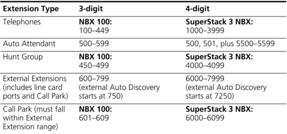
Autodiscovering Internal Telephones. The default dial plan for the NBX 100 allows you to allocate internal telephones to extension numbers 100 through 449. The default dial plan for the SuperStack 3 NBX system allows you to allocate internal telephones to extension numbers 1000 through 3999. If you autodiscover your company’s internal telephones, Auto Discovery usually begins at number 100 or 1000. However, for some countries, internal telephones begin at a higher number to allow you to directly dial numbers of “national importance.” Auto Discovery allocates telephone extensions numbers within this range. For more information on Auto Discovery, see “Using Auto Discovery for Initial System Configuration” in the NBX Installation Guide.
Dialing Outside Lines. To obtain an outside line, dial 9 or 0 as appropriate for your country.
WARNING:You must first obtain an outside line before you can dial emergency numbers.
Importing a User-Defined Dial Plan
To import a customer-defined (user-defined) dial plan configuration file:
1 In the NBX NetSet – Main Menu window, click Dial Plan. The Dial Plan window appears, displaying the Operations tab.
2 In the User-Defined File box, enter the path and name of the user-defined configuration file, or click Browse to find the file that you want.
The NBX system has no predefined location for dial plan configuration files. You can specify any directory or path that you want.
3 Click Import and reboot the system.
made syntax or content errors. Carefully check any changes that you make to the configuration file before you import them.
Exporting (Saving) a Dial Plan Configuration File
When you export (save) the current configuration, the system creates a new dial plan configuration file from the current database. You save the new text file using a name that you choose.
This example refers to Internet Explorer. If you use another browser, you may need to use slightly different procedures.
To export a dial plan configuration file:
1 In the NBX NetSet – Main Menu window, click Dial Plan. The Dial Plan window appears, displaying the Operations tab.
2 Click Export. The system constructs a new configuration file from the current values in the database and displays it. Figure 3 shows a partial display. Scroll your browser window to see your complete dial plan.
Figure 3 Dial Plan Configuration File (partial)
3 Click the File menu and select Save As.
4 From the list box at the top of the Save As window, select the destination folder.
Managing the Dial Plan Configuration File 49
The sample default files include examples of such things as timed routes and pretranslators. Verify that you rename the new configuration file with a unique file name so that you do not overwrite the sample default file.
6 Click Save.
Testing a Dial Plan This section describes how to test the currently loaded dial plan by placing a simulated call.
Even if the NBX system is completely installed and operational, a test places a simulated, not an actual call.
Example: If you have an entry in the dial plan for digit sequences starting with 91, with MIN and MAX set to 5, and you test the sequence 9123, the dial plan test reports an insufficient number of digits. However, in actual operation, the NBX system would time out waiting for the fifth digit, and then attempt to place the call. Assuming that the outside line prefix is 9 (such as in the United States), this situation would obtain an outside line (9) and then dial the numbers 123.
You can specify a day of the week and a time by selecting entries from the Day/Time list boxes. This choice instructs the system to act as if the day and time you select are the current day and time.
If you have timed routes defined in the dial plan, you use different day and time settings to determine whether the timed route works properly.
Example: Assume that you want a timed route to select route 35 during open business hours Monday through Friday, but route 36 when business is closed on those days and on weekends. After you define the timed route commands and import the modified file, you then test using days and times within business hours (to verify that the system selects route 35) and during closed hours and weekends (to verify that it selects route 36).
You can also use day and time settings to test whether the Class of Service settings operate as expected.
Example: You can config