AT&T
MERLIN LEGEND™
Communications System
Notice
Every effort was made to ensure that the information in this book was complete and accurate at the time of printing. However, information is subject to change.
Federal Communications Commission (FCC) and
Canadian Department Of Communications (DOC) Information For important FCC and DOC interference, registration, and repair
information, see “Customer Support Information” in this book.
Trademarks
Accunet is a registered trademark of AT&T. Dimension is a registered trademark of AT&T. Horizon is a registered trademark of AT&T.
Magic on Hold is a registered trademark of AT&T. Megacom is a registered trademark of AT&T. MERLIN is a registered trademark of AT&T. MERLIN LEGEND is a trademark of AT&T. MERLIN MAIL is a trademark of AT&T.
MLX-10, MLX-10D, MLX-20L, and MLX-28D are trademarks of AT&T. MultiQuest is a registered trademark of AT&T.
SYSTIMAX is a trademark of AT&T.
MS-DOS is a registered trademark of Microsoft Corporation.
PagePac is a registered trademark of DRACON, a Harris Corporation. Starset is a registered trademark of Plantronics Corporation.
Supra and StarMate are trademarks of Plantronics Corporation. UNIX is a registered trademark of UNIX System Laboratories, Inc. ZoneMate is a trademark of DRACON, a Division of Harris Corporation.
Support Telephone Number
MERLIN LEGEND™ Communications System Installation, Programming, and Maintenance
555-610-140
Ignore all references to the small processor module. The MERLIN LEGEND™ Communications System offers only one processor module. This processor module is referred to as a large processor module in this document.
Ignore references to the “small” processor module on the following pages:
Page 1-6, Processor Module.
Page 1-35, System Capacities, first, fourth, and sixth paragraphs.
Pages 1-36 - 1-37, Table 1-8, System Capacities.
Pages 1-38 - 1-40, Table 1-9, Feature Capacities.
Page 2-6, Backboard Requirements.
Page 3-10, Install the Feature Module in the Processor Module, first paragraph.
Appendix C - Page C-1
Ordering Codes Table: The following Price Element Codes (PECs) am not valid:
Small (Analog) - 6141-CUA Small (Digital) - 6141-CUD
Appendix C - Page C-2
Ordering Codes Table: The following Price Element Codes (PECs) are not valid:
Small (Analog) - 6141-24D
Customer Support Information
xv■ ■ ■ ■ ■ ■ ■ ■
Support Telephone Number
FCC Electromagnetic Interference Information DOC Interference Information
FCC Notification and Repair Information Installation and Operational Procedures DOC Notification and Repair Information Security
Warranty and Liability
xv xv xv xvi xvii xviii xxi xxii
About The Book
xxv■ ■ ■ ■ ■
Related Documentation xxv
How to Order Books xxvi
1
System Description
1-1 ■ ■ ■ ■ ■ ■ ■ ■ ■ ■ ■ ■Modes of Operation System Components Control Unit
Telephones and Consoles Adjuncts Adapters System Capacities Data Capabilities Networking Capabilities Functional Units Signal Processing DS1 Capabilities 1-2 1-4 1-5 1-26 1-34 1-34 1-35 1-41 1-42 1-45 1-47 1-53
2
Preparation
2-1■ ■ ■ ■ ■ ■
Planning Forms 2-2
Environment 2-5
Space and Location 2-6
Power and Grounding 2-8
Power Surge and Lightning Protection 2-14
3
Installation
3-1■ The Control Unit ■ Channel Service Unit
■ The SMDR Printer and the System
Programming PC
■ Data Adapters ■ System Wiring ■ IROB Protection
■ Telephones and Consoles ■ System Acceptance Test
3-2 3-19 3-45 3-56 3-77 3-102 3-103 3-116
4
Programming Procedures
■ System Programming ■ Programming Procedures
■ Set the Basic System Operating Conditions ■ System Renumbering
■ System Operator Positions ■ Lines and Trunks
■ DS1 Facilities ■ Tie Trunks ■ DID Trunks ■ PRI Facilities ■ Telephones
■ Auxiliary Equipment
■ Optional Telephone Features
Programming Procedures—Continued
■ Optional Group-Assigned Features 4-146
■ System Features 4-173
■ Automatic Route Selection 4-202
■ Night Service 4-215
■ Labeling 4-222
■ Backup, Restore, and Print System
Programming Reports 4-228
5
Maintenance and Troubleshooting
5-1■ Maintenance 5-1
■ Troubleshooting 5-46
6
Adapters, Accessories, and Applications
6-1■ Adapters 6-1
■ Accessories 6-4
■ Applications 6-8
A
Wiring
A-1■ Wiring Tables A-2
B
Adjuncts
B-1C
Product Ordering Information
C-1D
Unit Load Calculation Work Sheet
D-1E
General Telephone Programming
E-1■ Programming Methods E-2
F
General Feature Use
F-1G
Programming Special Characters
G-1I
System Programming Reports
I-1J
System Programming Menu Hierarchy
J-1K
Two-Digit Numbering Plan
K-1L
System Technician’s Run Sheet
L-1AB Abbreviations
ABB-1GL Glossary
GL-1IN Index
IN-1Illustrations
inside1
System Description
1-1 1-2 1-3 1-4 1-5 1-6 1-7 1-8 1-9 1-10 1-11Line/Trunk and Station Modules Touch-Tone Receiver Requirements Reusable MERLIN II Line/Trunk and Station Modules
Reusable MERLIN II Hardware Analog Multiline Telephones Single-Line Telephones
Telephones and Adjuncts Not Supported System Capacities
Feature Capacities Tie-Trunk Compatibility Line Compensation Settings
1-9 1-21 1-22 1-24 1-28 1-30 1-32 1-36 1-38 1-52 1-59
2
Preparation
2-1 Required Planning Forms 2-2 Required Planning Forms for
400EM, or 800 DID Modules 2-3 Optional Planning Forms 2-4 Environmental Requirements 2-5 AC Power Requirements
3
Installation
3-1 3-2 3-3 3-4 3-5 3-6 3-7 3-8 3-9 3-10 3-11 3-12 3-13 3-14 3-15 3-16 3-17 3-18 3-19 3-20 3-21SW1 Default Settings 3-21
SW2 Default Settings 3-22
SW4 Default Settings 3-23
SW5 Default Settings 3-24
SW6 Default Settings 3-25
SW7 Settings 3-26
SW2 BER Options 3-27
Switch Settings in Hybrid/PBX Mode:
Network and Equipment are ESF Framed 3-28 Switch Settings in Hybrid/PBX Mode:
Network and Equipment are D4 Framed 3-28 Switch Settings in Hybrid/PBX Mode:
Network is ESF Framed and Equipment
is D4 Framed 3-29
Switch Settings in Hybrid/PBX Mode: Network is D4 Framed and Equipment
is ESF Framed 3-29
Artificial Transmit Line Options 3-31 100D Module Pin Assignments 3-32 Wire-Wrap Connector Pin Assignments 3-32 DTE 15-Pin Connector Pin Assignments 3-33 Network 15-Pin Connector Pin Assignments 3-34
CSU Front Panel LEDs 3-35
CSU Front-Panel Controls 3-36 CSU Front-Panel Test Jacks 3-37
SMU Switch Settings 3-39
3-22 3-23 3-24 3-25 3-26 3-27 3-28 3-29 3-30 3-31 3-32 3-33 3-34
OR Artificial Line Options 3-40
SMU Front-Panel LEDs 3-42
SMU Front Panel Test Jacks 3-42 CSU Rear Panel Pin Assignments 3-44 AT&T 572 Printer Options 3-47 AT&T 475/476 Printer DIP Switch Settings 3-49
ISDN 7500B Data Module Option Settings
for Digital-to-Analog Modem Pool Operation 3-72 Modem Option Setting for Digital-to-Analog
Modem Pool Operation 3-73
ISDN 7500B Data Module Option Settings for Analog-to-Digital Modem Pool Operation 3-74 Modem Option Setting for Analog-to-Digital
Modem Pool Operation 3-75
Network Interfaces 3-79
CO Network Interface Codes 3-80
Insert Labels 3-97
4
Programming Procedures
5
Maintenance and Troubleshooting
5-1 Line/Trunk Errors 5-44
5-2 Maintenance Problems and Solutions 5-46
6
Adapters, Accessories, and
6-1 TTRs Required by VMS 6-2 Voice Channels Required 6-3 Number of Attendants
6-4 MERLIN MAIL Ports Required 6-32
Applications
6-10 6-23 6-28
A
Wiring
A-1 LS, GS/LS, DID, and OPT 6-Position
Jacks A-2
A-2 Tie-Trunk and DS1/PR1 8-Position Jacks A-2 A-3 Tie-Line Jack to RJ2GX Network
Interface A-3
A-4 T/R, Analog Multiline Telephone, and MLX
8-Position Station Jacks A-4 A-5 Eight-Pin RS-232 Flow Control Cable A-5
B
Adjuncts
technicians only. Technician qualification includes completion
of an AT&T hands-on instructor-led course covering installation and maintenance for this product. Installation or maintenance of this product by anyone other than a qualified service technician may void the warranty. Hazardous electrical voltages are
present inside this product
The exclamation point in an equilateral triangle is intended to alert the user to the presence of important operating and maintenance (servicing)
instructions in the literature accompanying the product.
IMPORTANT SAFETY INSTRUCTIONS
When installing telephone equipment, basic safety
precautions should always be followed to reduce the risk of fire, electric shock, and injury to persons, including:
■ Read and understand all instructions.
unless the telephone wiring has been disconnected at the network interface.
■ Use caution when installing or modifying telephone lines. ■ Use only AT&T manufactured MERLIN LEGEND™
Com-munications System circuit modules, carrier assemblies, and power units in the MERLIN LEGEND Communications System (511A) control unit.
■ Use only AT&T-recommended/approved MERLIN LEGEND
Communications System accessories.
■ If equipment connected to the analog station modules
(008/408/408 GS/LS) or to the MLX telephone module (008 MLX) is to be used for in-range out-of-building (IROB) applications, IROB protectors are required.
■ Do not install this product near water, for example, in a wet
basement location.
■ Do not overload wall outlets as this can result in the risk of
fire or electric shock.
■ The MERLIN LEGEND Communications System is
equipped with a three-wire grounding-type plug, a plug having a third (grounding) pin. This plug will fit only into a grounding-type power outlet. This is a safety feature. if you are unable to insert the plug into the outlet, contact an
electrician to replace the obsolete outlet. Do not defeat the safety purpose of the grounding plug.
■ The MERLIN LEGEND Communications System requires a
supplementary ground.
■ Do not attach the power supply cord to building surfaces.
Do not allow anything to rest on the power cord. Do not locate this product where the cord will be abused by persons walking on it.
■ Slots and openings in the module housings are provided
result in a risk of fire or electric shock. Never spill liquid of any kind on this product.
■ Unplug this product from the wall outlet before cleaning.
Support Telephone Number
AT&T provides a toll-free customer Helpline (1-800-628-2888)24 hours a day (U.S.A. only). Call the Helpline, or your authorized dealer, if you need assistance when installing, programming, or using your system.
Federal Communications Commission (FCC) Electromagnetic Interference Information
This equipment has been tested and found to comply with the limits for a Class A digital device, pursuant to Part 15 of the FCC Rules. These limits are designed to provide reasonable protection against harmful interference when the equipment is operated in a commercial environment. This
equipment generates, uses, and can radiate radio frequency energy and, if not installed and used in accordance with the instruction manual, may cause harmful interference to radio communications. Operation of this equipment in a residential area is likely to cause harmful interference, in which case the user will be required to correct the interference at his own expense.
Canadian Department of Communications (DOC) Interference Information
Le présent appareil numérique n'émet pas de bruits radioélectriques dépassant les limites applicable aux appareils numériques de la classe A prescrites dans le Règlement sur le brouillage radioélectrique édicté par le ministère des Communications du Canada.
FCC Notification and Repair Information
This equipment is registered with the FCC in accordance with Part 68 of its rules. In compliance with those rules, you are advised of the following:
■ Means of Connection. Connection of this equipment to the telephone
network shall be through a standard network interface jack: USOC RJ11C, RJ14C, RJ21X. Connection to E&M tie trunks requires a USOC RJ2GX. Connection to off-premises stations requires a USOC RJ11C or RJ14C. Connection to 1.544 Mbs digital facilities must be through a USOC RJ48C or RJ48X. Connection to DID requires a RJ11C, RJ14C or RJ21X. These USOCs must be ordered from your telephone company. This equipment may not be used with party lines or coin telephone lines.
■ Notification to the Telephone Companies. Before connecting this
equipment, you or your equipment supplier must notify your local telephone company’s business office of the following:
■ ■ ■ ■ ■ ■ ■
The telephone number(s) you will be using with this equipment. The appropriate registration number and ringer equivalence number (REN), which can be found on the back or bottom of the control unit is as follows:
If this equipment is to be used as Key System, report the following number AS593M-72914-KF-E and if the system
provides both manual and automatic selection of incoming/ outgoing access to the network, report AS593M-72682-MF-E. The ringer equivalence number for both systems is 1.5A.
For tie-line connection, provide the telephone company the facility interface code (FIC) of TL31M and the service order code (SOC) 9.0F.
For connection to off-premises stations, report the FIC OL13C and SOC 9.0F.
If this equipment is to be connected to digital service (1.544 Mbs), the FIC is 04DU9-B for D4 framing format or 04DU9-C for extended framing format, and SOC 6.0P.
If this equipment is to be connected to DID facilities, the FIC is 02RV2-T, and the SOC is 9.0F.
You must also notify your local telephone company if and when this equipment is permanently disconnected from the line(s).
The REN is used to determine the quantity of devices which maybe connected to the telephone line. Excessive REN’s on the telephone line may result in the devices not ringing in response to an incoming call. In most, but not all, areas the sum of the REN’s should not exceed five (5.0). To be certain of the number of devices that maybe connected to the line, as determined by the total REN’s, contact the telephone
company to determine the maximum REN for the calling area.
Installation and Operational Procedures
The manuals for your system contain information about installation and operational procedures.
■ Repair Instructions. If you experience trouble because your equipment
is malfunctioning, the FCC requires that the equipment not be used and that it be disconnected from the network until the problem has been corrected. Repairs to this equipment can be made only by the manufacturers, their authorized agents, or by others who maybe authorized by the FCC. In the event repairs are needed on this equipment, please contact the National Service Assistance Center (NSAC) at 1-800-628-2888, or your authorized AT&T dealer.
■ Rights of the Local Telephone Company. If this equipment causes
harm to the telephone network, the local telephone company may discontinue your service temporarily. If possible, they will notify you in advance. But if advance notice is not practical, you will be notified as soon as possible. You will also be informed of your right to file a complaint with the FCC.
Your local telephone company may make changes in its facilities, equipment operations, or procedures that affect the proper functioning of this equipment. If they do, you will be notified in advance to give you an opportunity to maintain uninterrupted telephone service.
■ Hearing Aid Compatibility. The custom telephone sets for this system
are compatible with inductively coupled hearing aids as prescribed by the FCC.
■ Automatic Dialers. WHEN PROGRAMMING EMERGENCY NUMBERS
AND/OR MAKING TEST CALLS TO EMERGENCY NUMBERS:
■ Remain on the line and briefly explain to the dispatcher the reason
for the call.
DOC Notification and Repair Information
NOTICE: The Canadian Department of Communications (DOC) label
identifies certified equipment. This certification means that the equipment meets certain telecommunications network protective, operational, and safety requirements. The DOC does not guarantee the equipment will operate to the user’s satisfaction.
Before installing this equipment, users should ensure that it is permissible to connect it to the facilities of the local telecommunications company. The equipment must also be installed using an acceptable method of
connection. In some cases, the company’s inside wiring for single-line individual service may be extended by means of a certified connector assembly (telephone extension cord). The customer should be aware that compliance with the above conditions may not prevent degradation of service in some situations.
Repairs to certified equipment should be made by an authorized Canadian maintenance facility designated by the supplier. Any repairs or alterations made by the user to this equipment, or any equipment malfunctions, may give the telecommunications company cause to request the user to disconnect the equipment.
Users should ensure for their own protection that the electrical ground connections of the power utility, telephone lines, and internal metallic water pipe system, if present, are connected. This precaution maybe particularly important in rural areas.
CAUTION: Users should not attempt to make such connections
themselves, but should contact the appropriate electric inspection authority or electrician, as appropriate.
To prevent overloading, the Load Number (LN) assigned to each terminal device denotes the percentage of the total load to be connected to a telephone loop used by the device. The termination on a loop may consist of any combination of devices subject only to the requirement that the total of the Load Numbers of all the devices does not exceed 100.
Renseignements sur la notification du ministère des Communications du Canada et la réparatione
AVIS: L'étiquette du ministère des Communications du Canada identifie le
matériel homologué. Cette étiquette certifie que le matériel est conforme à certaines normes de protection, d'exploitation et de sécurité des réseaux de télécommunications. Le Ministère n’assure toutefois pas que le matériel fonctionnera à la satisfaction de l’utilisateur.
Avant d'installer ce matériel, l'utilisateur doit s’assurer qu'il est permis de le raccorder aux installations de l’entreprise locale de télécommunication. Le matériel doit également etre installé en suivant une méthode acceptée de raccordement. Dans certains cas, les fils intérieurs de l’enterprise utilisés pour un service individuel à ligne unique peuvent être prolongés au moyen d’un dispositif homologué de raccordement (cordon prolongateur
téléphonique interne). L'abonné ne doit pas oublier qu'il est possible que la conformité aux conditions énoncées ci-dessus n’empêchent pas la
dégradation du service dans certaines situations. Actuellement, les
entreprises de télécommunication ne permettent pas que l'on raccorde leur matériel à des jacks d'abonné, sauf dans les cas précis prévus pas les tarifs particuliers de ces entreprises.
Les réparations de matériel homologué doivent être effectuées pas un centre d'entretien canadien autorisé désigné par le fournisseur. La compagnie de télécommunications peut demander à l'utilisateur de débrancher un appareil à la suite de réparations ou de modifications effectuées par l’utilisateur ou à cause de mauvais fonctionnement. Pour sa propre protection, l'utilisateur doit s'assurer que tous les fils de mise à la terre de la source d'énergie électrique, des lignes téléphoniques et des canalisations d'eau métalliques, s'il y en a, sont raccordés ensemble. Cette précaution est particulièrement importance dans les régions rurales.
AVERTISSEMENT: L'utilisateur ne doit pas tenter de faire ces
raccordements lui-même; il doit avoir recours à un service d'inspection des installations électriques, ou à un electricien, selon le cas.
L'indice de charge (IC) assigné à chaque dispositif terminal indique, pour éviter toute surchage, le pourcentage de la charge totale qui peut être raccordée à un circuit téléphonique bouclé utilisé par ce dispositif. La terminaison du circuit bouclé peut être constitutée de n'importe quelle
This device complies with Part 15 of the FCC Rules. Operation is
AT&T
MERLIN LEGEND™
subject to the following two conditions. (1) this device may not cause harmful interference. and (2) this device must accept any interference received, including interference that may cause undesired operation
Model
511
A Control Unit
Complies with Part 68 FCC Rules FCC Reg. No AS593M-72682-MF-E Ringer Equivalence 1.5A. When equipped
LISTED
TELEPHONE
with th
e
KF option (key only), FCC Reg. No.
538E
EQUIPMENT
LR 56260
AS593M-72914-KF-E Ringer Equivalence 1.5A.
MADE IN USA Use only AT&T manufactured MERLIN LEGEND circuit modules. career assemblies, and power units. as specified in the Installation Manual, in this product. There are no user serviceable parts inside. Contact your authorized agent for service and repair This digital apparatus does not exceed the Class A limits for radio noise emissions set out in the radio interference regulations of the Canadian Department of Communications. Le présent appareil numérique n'émet pas de bruits radioélectriques dépassant les limites applicables aux appareils numériques de la classe A prescrites dans le Réglement sur le brouillage radioélectrique édicté par le ministére des Communications du Canada.
WARNING:
out-of-building If equipment is used for applications, approvedsecondary protectors are required. See Installation Manual.
AVERTISSEMENT
Si l'équipment est
Security of Your System—Preventing Toll Fraud
As a customer of a new telephone system, you should be aware that there exists an increasing problem of telephone toll fraud. Telephone toll fraud can occur in many forms, despite the numerous efforts of telephone companies and telephone equipment manufacturers to control it. Some individuals use electronic devices to prevent or falsify records of these calls. Others charge calls to someone else’s number by illegally using lost or stolen calling cards, billing innocent parties, clipping on to someone else’s line, and breaking into someone else’s telephone equipment physically or electronically. In certain instances, unauthorized individuals make connections to the telephone network through the use of remote access features.
The Remote Access feature of your system, if you choose to utilize it, permits off-premises callers to access the system from a remote telephone by using an 800 number or a 7- or 10- digit telephone number. The system returns an acknowledgement signaling the user to key in his or her
authorization code, which is selected and administered by the system manager. After the authorization code is accepted, the system returns dial tone to the user. If you do not program specific egress restrictions, the user will be able to place any call normally dialed from a telephone associated with the system. Such an off-premises network call is originated at, and wiII be billed from, the system location.
The Remote Access feature, as designed, helps the customer, through proper administration, to minimize the ability of unauthorized persons to gain access to the network. Most commonly, phone numbers and codes are compromised when overheard in a public location, through theft of a wallet or purse containing access information, or through carelessness (writing codes on a piece of paper and improperly discarding it). Additionally, hackers may use a computer to "dial" an access code and then publish the information to other hackers. Enormous charges can be run up quickly. It is the customer’s responsibility to take the appropriate steps to properly implement the features, evaluate and administer the various restriction levels, protect access codes, and distribute access codes only to individuals who have been fully advised of the sensitive nature of the access information.
Common carriers are required by law to collect their tariffed charges. While these charges are fraudulent charges made by persons with criminal intent, applicable tariffs state that the customer of record is responsible for
To minimize the risk of unauthorized access to your communications system:
■ ■
■
■ ■
■
■ ■
■
Use a nonpublished Remote Access number.
Assign authorization codes randomly to users on a "need-to-have" basis, keeping a log of ALL authorized users and assigning one code to one person.
Use random sequence authorization codes, which are less likely to be easily broken.
Deactivate all unassigned codes promptly.
Ensure that Remote Access users are aware of their responsibility to keep the telephone number and any authorization codes secure.
When possible, restrict the off-network capability of off-premises callers, via use of Call Restrictions and Disallowed List capabilities.
When possible, block out-of-hours calling.
Frequently monitor system call detail reports for quicker detection of any unauthorized or abnormal calling patterns.
Limit Remote Call Forward to persons on a “need-to-have” basis.
Limited Warranty and Limitation of Liability Limited Warranty
AT&T warrants to you, the customer, that your MERLIN LEGEND
Communications System will be in good working order on the date AT&T or its authorized reseller delivers or installs the system, whichever is later (“Warranty Date"). If you notify AT&T or its authorized reseller within one year of the Warranty Date that your system is not in good working order, AT&T will without charge to you repair or replace, at its option, the system components that are not in good working order. Repair or replacement parts may be new or refurbished and will be provided on an exchange basis. If AT&T determines that your system cannot be repaired or replaced, AT&T will remove the system and, at your option, refund the purchase price of your system, or apply the purchase price towards the purchase of
If you purchased your system directly from AT&T, AT&T will perform
warranty repair in accordance with the terms and conditions of the specific type of AT&T maintenance coverage you selected. A written explanation of AT&T’s types of maintenance coverage maybe obtained from AT&T by calling 1-800-247-7000. If you purchased your system from an AT&T authorized reseller, contact your reseller for the details of the maintenance plan applicable to your system.
This AT&T limited warranty covers damage to the system caused by power surges; including power surges due to lightning.
The following will not be deemed to impair the good working order of the system, and AT&T will not be responsible under this limited warranty for damages resulting from
■ failure to follow AT&T’s installation, operation, or maintenance
instructions
■ unauthorized system modification, movement, or alteration
■ unauthorized use of common carrier communication services accessed
through the system
■ abuse, misuse, or negligent acts or omissions of the customer and
persons under the customer’s control
■ acts of third parties and acts of God
AT&T’S OBLIGATION TO REPAIR, REPLACE, OR REFUND AS SET FORTH ABOVE IS YOUR EXCLUSIVE REMEDY.
Limitation Of Liability
EXCEPT FOR PERSONAL INJURY, DIRECT DAMAGES TO TANGIBLE PERSONAL PROPERTY PROXIMATELY CAUSED BY AT&T, AND LIABIILlTY OTHERWISE EXPRESSLY ASSUMED IN A WRITTEN AGREEMENT SIGNED BY AT&T, THE LIABILITY OF AT&T, ITS AFFILIATES, SUPPLIERS AND AUTHORIZED RESELLERS FOR ANY CLAIMS, LOSSES, DAMAGES OR EXPENSES FROM ANY CAUSE WHATSOEVER (INCLUDING ACTS OR OMISSIONS OF THIRD PARTIES) REGARDLESS OF THE FORM OF ACTION, WHETHER IN CONTRACT, TORT OR OTHERWISE, SHALL NOT EXCEED AMOUNT EQUAL TO THE LESSER OF THE DIRECT
DAMAGES PROVEN OR THE PURCHASE PRICE OF THE SYSTEM. IN NO EVENT SHALL AT&T OR ITS AFFILIATES, SUPPLIERS OR AUTHORIZED RESELLERS BE LIABLE FOR INCIDENTAL, RELIANCE, CONSEQUENTLY, OR ANY OTHER INDIRECT LOSS OR DAMAGE (INCLUDING LOST
This book provides technical information about the operation and installation of the communications system. It is intended for
qualified technicians who install, maintain, and repair the communications system.
Related Documentation
The following books are available to help you set up, use, and maintain the communications system:
■ reference
■ setup and modification ■ telephone user support ■ operator guides
How to Order Books
The books needed for operating the communications system were supplied with the system. You can order additional copies of these and other books listed below from the AT&T Customer
Information Center:
■ Within the continental United States, call 1-800-432-6600. ■ In Canada, call 1-800-255-1242.
MERLIN LEGEND Communications
System Book Title Order Number
System Reference
System Reference 555-610-110
System Setup and Modification
Key System Planning Forms only 555-610-116 Key System Planning and Key
System Planning Forms 555-610-112
PBX System Planning Forms only 555-610-117 PBX System Planning and PBX
System Planning Forms 555-610-113
Data Planning Forms only 555-610-118
Data Guide and Data Planning Forms 555-610-114
MERLIN LEGEND Communications
System Book Title Order Number
Telephone User Support Analog Multiline Telephones
User's Guide 555-610-120
MLX-10D,™ MLX-28D,™ and MLX-20L™ Digital Display Telephones
User’s Guide 555-610-122
MLX-10™ Digital Non-Display
Telephone User's Guide 555-610-123
MLX-10™ and MLX-10D™ User Cards 555-610-124 MLX-28D™ and MLX-20L™ User Cards 555-610-125 Single-Line Telephones User’s Guide 555-610-121
Operator Guides
Analog Direct-Line Consoles
Operator’s Guide 555-610-131
Digital/ISDN Direct-Line Consoles
Operator’s Guide 555-610-132
Digital/ISDN Queued Call Console
Operator’s Guide 555-610-133
Miscellaneous
Additional Ordering
Information
For information on ordering replacement parts, accessories, and other equipment that is compatible with the system, see
Appendix A in System Reference.
Product Safety Labels
Throughout this book, hazardous situations are indicated by an exclamation point inside a triangle, along with the word caution or warning.
How to Comment on This
Book
WARNING
Warning indicates the presence of a hazard that could cause death or severe personal injury if the hazard is not avoided.
CAUTION:
Caution indicates the presence of a hazard that will or can cause minor personal injury or property damage if the hazard is not avoided.
We welcome your feedback on this book. Please use the feedback form that follows. If the form is missing, send your comments to A. Sherwood, AT&T, 99 Jefferson Road,
The MERLIN LEGEND™ Communications System is an
Modes of Operation
The system is designed for customers in the 10- to 100-station range. It can be configured to operate in one of three modes:
■ Hybrid/PBX ■ Key
■ Behind Switch
Hybrid/PBX Mode
The Hybrid/PBX mode handles a large volume of calls and users and provides the most flexibility of the three modes. Outside facilities consist of Ioop-start trunks, ground-start trunks, direct inward dialing (DID) trunks, tie trunks, and Digital Signal 1 (DS1) facilities. The trunks can be grouped in pools for shared use. In addition, trunks can be assigned to line buttons on multiline telephones for users who need a personal line.
Users access inside lines and outside trunks via system access buttons. To make an outside call, the user enters a dial-out code (usually a 9), and the system automatically selects an available trunk. The Automatic Route Selection feature determines which trunk should be used for each type of outgoing call.
Incoming calls can be handled by a direct-line console (DLC) or a queued call console (QCC), or by a combination of both
Key Mode
In the Key mode, each outside line appears on a button on one or more multiline telephones. The line buttons allow users to see activity on other telephones, join conversations, place calls, or receive calls. Separate intercom buttons are used to make and receive internal calls.
A Key system automatically assigns the first eight outside lines to all telephones. This arrangement can be customized through system programming by assigning lines to individual telephones or to selected groups of telephones.
Behind Switch Mode
System Components
The system consists of required and optional components:
■ required components
■ control unit ■ telephones
■ optional components
■ adjuncts ■ adapters ■ applications
Control Unit
The control unit (CU) connects central office (CO) lines with telephones and adjuncts such as answering machines and fax machines. The CU consists of the following components:
■ control unit housing ■ carrier(s)
■ power supply module (one per carrier) ■ processor module
■ line/trunk and station modules
Control Unit Housing
The control unit is housed in a plastic cabinet for protection. The size of the housing increases as expansion carriers are added to the CU. Figure 1 shows how the control unit housing fits around the CU.
Carriers
The basic and expansion carriers each have seven slots to hold modules (see Figure 2). The basic carrier contains a power supply module, the processor module (slot 00), and line/trunk and station modules (slots 01–05).
Up to two expansion carriers can be added to the right side of the basic carrier to increase the capacity of the system. Like the basic carrier, the leftmost and widest slot of the expansion
carrier holds a power supply module; the remaining six slots hold line/trunk and station modules.
Power Supply Modules
The power supply module provides power to the carrier, to each telephone, and to adjuncts—except for adjuncts such as
answering machines and fax machines that have their own power supplies. Each carrier requires its own power supply module, which goes into the first slot on the carrier.
The power supply module converts 117-VAC line voltage to these outputs: +5 VDC, -5 VDC, and -48 VDC. All modules use +5 VDC and -5 VDC for logic and analog transmission circuits. Most line/trunk and station modules use -48 VDC for power to the stations. The direct inward dialing (DID) and off-premises
telephone (OPT) line/trunk and station modules also provide -48 VDC on the tip/ring (T/R) interface to the CO or OPT station. The 012 basic telephone module provides 21 VDC to single-line telephones and equipment.
When single-line telephones are connected to a 012, 800 DID, or 008 OPT module, a 129B Frequency Generator (ring generator) must be installed in the power supply module of each carrier that houses one or more of these modules.
A green light on the power supply module remains on as long as the module is receiving power. The power supply module also
has an on/off switch and a modular telephone jack for
connecting an auxiliary power unit as needed (see Figure 3).
Processor Module
Placed in slot 00 of the basic carrier, the processor module controls system features and programming via the processor and memory boards and the feature module. The processor module comes in small and large versions. The small processor module supports up to 24 CO or tie lines/trunks and 56 stations. The large processor module supports up to 80 CO or tie
The main board contains the 68000 microprocessor, a built-in 1200-baud data modem, built-in diagnostics, RAM, a real-time clock, and interrupt circuitry, and interfaces to the other modules through the I/O bus on the carrier backplane.
The processor module has two modular RS-232 jacks: one for Station Message Detail Recording (SMDR) and the other for system programming and maintenance via a personal computer (see Figure 3).
A NiCad battery in the processor module provides backup power for the real-time clock and nonvolatile RAM in case of power failure or system shutdown. The battery provides RAM data retention for 12 to 30 days. The trickle-charge circuit can recharge the battery to 50 percent of capacity from a discharged state in 48 hours. The minimum battery life is five years.
Line/Trunk and Station Modules
The line/trunk and station modules have jacks for connecting the CO lines/trunks and the station lines to the CU. The station lines connect to telephones and adjuncts.
There are different types of lines/trunks for the different functions of each mode. A Key or Behind Switch system can use
■ loop-start (LS) lines ■ tie trunks
■ a DS1 facility programmed for either T1 or Integrated
Services Digital Network Primary Rate Interface (ISDN-PRI) operation
■ a ground-start (GS) line only when registered under the MF
FCC classification
A Hybrid/PBX system can use
■ loop-start trunks ■ ground-start trunks ■ tie trunks
■ direct inward dialing (DID) trunks
■ a DS1 facility programmed for either T1 or ISDN-PRI
operation
The names of modules consist of a number identifying the number of lines/trunks and/or stations that can be connected to the module, followed by the types of lines and/or telephones it supports. For example, the 408 GS/LS module provides four line jacks and eight station jacks and supports ground-start or loop-start lines.
The system supports 13 types of line/trunk and station modules (see Figure 4). Table 1-1 lists the specifications for each type of module.
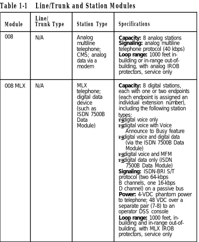
Table 1-1 Line/Trunk and Station Modules
Line/
Module Trunk Type Station Type Specifications
008 N/A Analog Capacity: 8 analog stations
multiline Signaling: analog multiline
telephone; telephone protocol (40 kbps)
CMS; analog Loop range: 1000 feet
in-data via a building or in-range
out-of-modem building, with analog IROB
protectors, service only
008 MLX N/A MLX Capacity: 8 digital stations,
telephone; each with one or two endpoints
digital data (each endpoint is assigned an
device individual extension number),
(such as including the following station
ISDN 7500B types:
Data ■ digital voice only
Module) ■ digital voice with Voice
Announce to Busy feature
■ digital voice and digital data
(via the ISDN 7500B Data Module)
■ digital voice and MFM
■ digital data only (ISDN
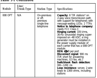
Table 1-1 Continued
Line/
Module Trunk Type Station Type Specifications
008 OPT N/A On-premises Capacity: 8 T/R stations* on
or off- 2-way voice transmission path
premises with support for telephones with
single-line message-waiting LEDs; 2 TTRs
telephone Notice to telephone company:
meets FCC Class C
Ringing current: 105-Vrms, 30-Hz sinusoidal ringing super-imposed on -48 VDC; a ring generator must be installed in the power supply module of each carrier that has a 008 OPT module.
REN: ≥ 1.0 per port
Disconnect signal: 900 ms (T/R short for answering machines, G3 fax, etc.) Switchhook flash detection: 300—1200 ms
Loop resistance: serves 2-wire loops to 1300 ohms, including stations
Table 1-1 Continued
Line/
Module Trunk Type Station Type Specifications
012 N/A Single-line Capacity: 12 T/R stations on
telephone; 2-way voice transmission path
MERLIN with support for telephones with
Attendant; message-waiting LEDs; 2 TTRs
MERLIN Power: 21-VDC, 600-ohm
MAIL™ Voice battery source
Messaging Ringing current: 105-Vrms,
System; 30-Hz sinusoidal ringing
super-T/R adjunct imposed on -48 VDC; a ring
(such as an generator must be installed in
answering or the power supply module of
a fax each carrier that has a 012
machine); module.
analog data REN: ≥ 1.0 per port
device (such Disconnect signal: 900 ms
as a modem) (T/R short for answering
machines, G3 fax, etc.) Switchhook flash detection: 300—1200 ms
1OOD T1 or PRI N/A Capacity: 24 lines/trunks for
voice and analog data or 23 lines/trunks for voice and data with 1-channel used for signaling
Mode: multiplexes 23 or 24 lines/trunks into 1 facility and demultiplexes one facility into 23 or 24 lines/trunks
Speed: up to 64 kbps
Signaling: DS1 over 4-wire; T1 uses RBS or CCS; PRI has ISDN-PRI
Table 1-1 Continued
Line/
Module Trunk Type Station Type Specifications
400† LS and TTR PFT Capacity: 4 lines/trunks,
telephone 4 TTRs, 1 PFT telephone
Signaling: LS
400EM Tie trunk N/A Capacity: 4 tie trunks
Method of Completion: automatic-start, immediate-start, wink-immediate-start, or delay-dial-start
Signaling: E&M type 1S, type 1C, type 5
400 GS/ LS or GS and PFT
LS/TTR TTR telephone; 4 TTRs, 1 PFT telephoneCapacity: 4 lines/trunks,
button Signaling: LS or GS, optioned
needed for per port
GS PFT telephone
408† LS Analog Capacity: 4 Iines/trunks,
multiline 8 stations, 1 PFT telephone
telephone; Station signaling: analog
CMS; PFT multiline telephone (40 kbps)
telephone Signaling: LS Iine/trunk: analog
voice
Loop range: 1000 feet, in-building and in-range out-of-building, with analog IROB protectors, service only
† Although these MERLIN II modules are supported in the MERLIN LEGEND
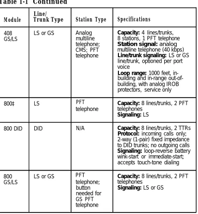
Table 1-1 Continued
Line/
Module Trunk Type Station Type Specifications
408 LS or GS Analog Capacity: 4 Iines/trunks,
GS/LS multiline 8 stations, 1 PFT telephone
telephone; Station signal: analog
CMS; PFT multiline telephone (40 kbps)
telephone Line/trunk signaling: LS or GS
line/trunk, optioned per port voice
Loop range: 1000 feet, in-building and in-range out-of-building, with analog IROB protectors, service only
800‡ LS PFT Capacity: 8 lines/trunks, 2 PFT
telephone telephones
Signaling: LS
800 DID DID N/A Capacity: 8 Iines/trunks, 2 TTRs
Protocol: incoming calls only; 2-way (1-pair) fixed impedance to DID trunks; no outgoing calls Signaling: loop-reverse battery wink-start or immediate-start; accepts touch-tone dialing
800 LS or GS PFT Capacity: 8 lines/trunks, 2 PFT
GS/LS telephone; telephones
button Signaling: LS or GS
needed for GS PFT telephone
‡ Although this MERLIN II module is supported in the MERLIN LEGEND Communications System, the 800 GS/LS is the recommended module.
Loop-Start Lines/Trunks
Loop-Start Lines/Trunks
LS lines/trunks are the standard for home and small business Key systems. They are less expensive in some areas but have certain limitations:
■ They do not protect against "glare." (Glare occurs when a
person tries to make an outside call on a line/trunk at the same time an incoming call is being received on that line/trunk.)
■ They have higher cable losses than GS lines/trunks ■ They cannot assure secure toll restriction.
Ground-Start Lines/Trunks
GS lines/trunks are outside lines/trunks used by some
businesses (such as hotels or motels) because the improved signaling of GS allows more secure toll restriction.
In addition, GS lines/trunks prevent glare and provide cable losses less than or equal to 4.5 dB.
The following types of outside lines/trunks come in either GS or LS form:
■ basic lines
■ WATS (wide area telecommunications service) ■ 800 service (In-WATS)
Tie Trunks
Tie trunks provide private communication between two systems. Tie trunks “tie” the two systems together, making it seem that all the telephones are on the same system. (See "Networking Capabilities" in this chapter for more information on how tie trunks connect to other systems.)
Tie trunks provide efficient communication between systems at different locations. These locations can be different floors of the same building, different buildings in the same campus, or different cities or states.
Tie trunks can be added to the system via the 400EM module. The 400EM module has four ports that must be programmed individually by selecting trunk options and setting the DIP (dual in-line package) switches, located on the front of the module, for different signaling modes and types (see Figure 72).
The following tie-trunk options need to be programmed:
■ Direction
■ Two-way (factory setting). Calls can be made in either
direction.
■ Outgoing only. Calls can be dialed but not received (no
ringing).
■ Incoming only. Calls can be received but not dialed (no
dialing).
■ Signaling Type can be any of the following types,
programmed via the 400EM module. The type of signal can be set separately for incoming and outgoing calls; for
■
■
■
■
■
■
Wink-start (factory setting). The originating end of the tie trunk transmits an off-hook signal and waits for the remote end to send back a signal (a wink) indicating that it is ready to receive dialing information.
Immediate-start. No start signal is necessary, and dialing can begin immediately after the tie trunk is seized.
Delay-dial-start. The originating end of the tie trunk
transmits an off-hook signal and waits for the remote end to send an off-hook signal followed by an on-hook signal. Automatic-start. Incoming calls are routed directly to another station without a start signal. In other words, when you pick up the handset, the signal rings immediately at the other end. This is also called an automatic-ringdown tie trunk.
Wink-start, immediate-start, and delay-dial-start are also called dial-repeating tie trunks.
E&M Signal
■ Type 1 standard (factory setting) ■ Type 1 compatible
■ Type 5
Dial Mode determines the incoming and outgoing dial.
modes:
■ rotary (factory setting) ■ touch-tone
Note: If the 400EM module is administered for touch-tone
■ Dial Tone determines whether the system returns a dial tone
to the remote end of the line:
■ yes (factory setting)—a dial tone is sent to the remote end ■ no—a dial tone is not sent to the remote end
■ Answer Supervision Time sets a time limit in milliseconds
(ms) for the remote station to signal the calling station:
■ 300 ms (factory setting)
■ 20–4800 ms (increments of 20 ms)
■ Disconnect Time sets a time limit in milliseconds for the
release of the E or M lead:
■ 300 ms (factory setting)
■ 140–2400 ms (increments of 10 ms) Direct Inward Dialing Trunks
Direct inward dialing (DID) trunks allow incoming calls to reach specific individuals or facilities in the system without the
assistance of a system operator. DID trunks are available only in the Hybrid/PBX mode. They are connected to the system on an 800 DID module.
With DID service, the customer reserves blocks of DID numbers from the local telephone company. The DID number should correspond to the extension number for an individual or a calling group, or to the code for Remote Access or pool dial-out.
CAUTION:
Because DID trunks allow calls to come directly to a telephone extension, they cannot be pooled. The CO passes the necessary digits to the system, which delivers the call directly to the dialed extension.
The system can receive 1- to 4-digit extension numbers over the DID trunks. The number of digits received on a specific DID trunk is always the same for that trunk; however, different DID trunks can receive different numbers of digits.
If the extension numbers used in the system are fewer than four digits but the CO sends four, the system can be programmed to ignore the leading digit(s). For example, if the DID number sent by the CO is 2157, the extension numbers the system can access are 57, 157, or 2157. System programming determines the proper extension number to connect.
The system also can be programmed to match more digits than are received from the CO. Additional leading digits are taken from the 4-digit trunk number, as programmed. For example, if the system is setup to match three digits and the CO sends only two, programming determines which DID trunk number prefix to add to complete the match and connect the call.
No routing of calls is made until the designated number of digits is received. Incoming DID numbers that don’t match a valid extension are either directed to a predesignated extension, such as the system operator, or the system sends back a reorder tone (fast busy).
The options for each DID trunk group are as follows:
■ Type
■ wink-start (factory setting) ■ immediate-start
■ Expected Digits
■ 3 (factory setting) ■ 1–4
■ Delete Digits
■ 0 (factory setting) ■ 0–4
■ Add Digits
■ 0 (factory setting)
■ 1- to 4-digit number (1 to 9999)
■ SignaIing
■ rotary (factory setting)
■ touch-tone
■ Invalid Destination
■ backup position (factory setting) ■ return to fast busy
100D Module
Touch-Tone Receivers
The 800 DID, 008 OPT, and 012 modules each provide two TTRs. Normally these TTRs are sufficient to handle calls originated on the 012 or 008 OPT module or received on the 800 DID module. However, additional TTRs maybe needed to support the following services:
■ tie trunks and DS1 emulated tie trunks set for Dual-Tone
Multifrequency (DTMF) signaling
■ Remote Access ■ Account Code Entry
■ AUDIX Voice Power (AVP)—IS II or Integrated Voice Power
Automated Attendant (IVP AA)—IS II applications
If more TTRs are needed to support these services, 400 or 400 GS/LS/TTR modules can be added (each module provides four TTRs). Table 1-2 shows the estimated number of TTRs needed in the system, depending on the call volume and the types of
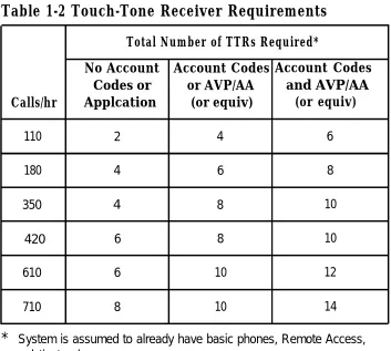
Table 1-2 Touch-Tone Receiver Requirements
Total Number of TTRs Required*
No Account Account Codes Account Codes Codes or or AVP/AA and AVP/AA Calls/hr Applcation (or equiv) (or equiv)
110 2 4 6
180 4 6 8
350 4 8 10
420 6 8 10
610 6 10 12
710 8 10 14
* System is assumed to already have basic phones, Remote Access,
and tie trunks.
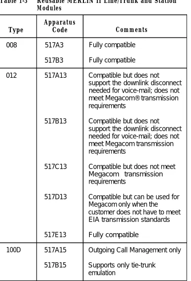
Reusable MERLIN® II Modules
Table 1-3 Reusable MERLIN II Line/Trunk and Station Modules
Apparatus
Type Code Comments
008 517A3 Fully compatible 517B3 Fully compatible
012 517A13 Compatible but does not
support the downlink disconnect needed for voice-mail; does not meet Megacom® transmission requirements
517B13 Compatible but does not
support the downlink disconnect needed for voice-mail; does not meet Megacom transmission requirements
517C13 Compatible but does not meet Megacom transmission requirements
517D13 Compatible but can be used for Megacom only when the
customer does not have to meet EIA transmission standards 517E13 Fully compatible
100D 517A15 Outgoing Call Management only 517B15 Supports only tie-trunk
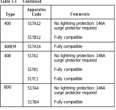
Table 1-3 Continued Apparatus
Type Code Comments
400 517A12 No lightning protection; 146A surge protector required 517B12 Fully compatible
400EM 517A14 Fully compatible
408 517A1 No lightning protection; 146A surge protector required 517B1 Fully compatible
517C1 Fully compatible
800 517A4 No lightning protection; 146A surge protector required 517B4 Fully compatible
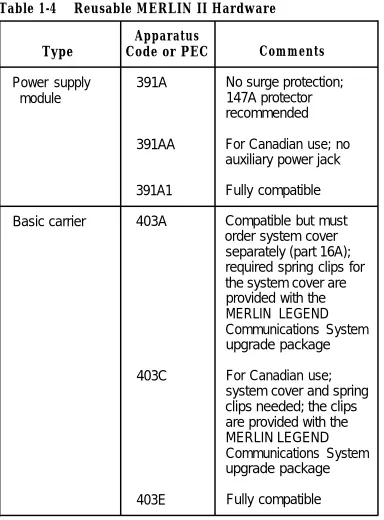
Reusable MERLIN II Hardware
Table 1-4 Reusable MERLIN II Hardware Apparatus
Type Code or PEC Comments
Power supply 391A No surge protection;
module 147A protector
recommended
391AA For Canadian use; no auxiliary power jack 391A1 Fully compatible Basic carrier 403A Compatible but must
order system cover separately (part 16A); required spring clips for the system cover are provided with the MERLIN LEGEND
Communications System upgrade package
403C For Canadian use;
system cover and spring clips needed; the clips are provided with the MERLIN LEGEND
Communications System upgrade package
Table 1-4 Continued
Apparatus Type
Expansion carrier
Frequency generator
(ring generator) Auxiliary power
Music coupler
Code or PEC
403B
403D
403F 129B
335A
61398
Comments
Compatible but must order system cover separately (part 17A) For Canadian use;
system cover and spring clips needed; the clips are provided with the MERLIN LEGEND
Communications System upgrade package
Fully compatible Fully compatible
Telephones and Consoles
Several different analog and single-line telephones work with the system; however, the only digital telephones that work with the system are the digital/ISDN (MLX) telephones.
W A R N I N G
An analog or digital multiline telephone located in a different building but within 1000 feet of the CU requires an IROB (in-range out-of-building) protector at each building entrance.
See Appendix C for ordering information on these telephones.
MLX Telephones
There are four new telephones in the MLX telephone line, all of which support ISDN capabilities:
■ MLX-20L™ telephone ■ MLX-28D™ telephone ■ MLX-10D™ telephone ■ MLX-10™ telephone
Some features are common to all MLX telephones:
■ programmable line and feature buttons with two associated
lights (red and green)
Note: An MLX-20L telephone used as a QCC has no
programmable buttons.
■ dedicated feature buttons (four have a red or green light) ■ red message-waiting light
■ built-in speakerphone
■ user reference card tray with feature and programming codes
and directory lists
■ optional interns Multi-Function Module (MFM) to connect to
tip/ring (T/R) equipment and alerting devices (described in Chapter 3)
Note: An MLX-20L telephone used as a QCC cannot have an
MFM in it.
■ two-position adjustable desk stand ■ four-pair modular line cord
MLX telephones with display have two additional features:
■ LCD display
■ display-associated keys
A list of features specific to each telephone model in the MLX telephone family follows.
MLX-20L Telephone (see Figure 5)
■ can be used for system programming and as a DLC or a
QCC operator console
■ 20 line and feature buttons ■ display (7 lines x 24 characters) ■ 14 display-associated buttons
■ accommodates one or two Direct Station Selectors (DSSs)
MLX-28D Telephone (see Figure 6)
■ 8 display-associated buttons
■ accommodates one or two Direct Station Selectors (DSSs)
MLX-10D Telephone (see Figure 7)
■ 10 line and feature buttons ■ desktop or wall-mount
■ display (2 lines x 24 characters) ■ 8 display-associated buttons
MLX-10 Telephone (see Figure 8)
■ 10 line and feature buttons ■ desktop or wall-mount
Analog Multiline Telephones
In addition to the MLX telephones, the analog multiline telephones in Table 1-5 can be connected to the system.
Table 1-5 Analog Multiline Telephones Model
5-button*
10-button* 34-button* 34-button Deluxe*
Description
5-button telephone with membrane. No adjuncts are supported with this telephone.
10-button telephone with membrane
34-button basic telephone with membrane Deluxe 34-button telephone with membrane
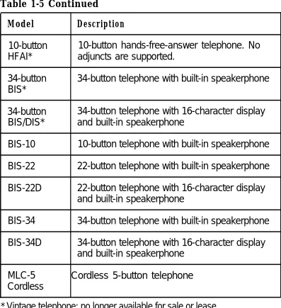
Table 1-5 Continued
Model Description
10-button 10-button hands-free-answer telephone. No HFAI* adjuncts are supported.
34-button 34-button telephone with built-in speakerphone BIS*
34-button 34-button telephone with 16-character display BIS/DIS* and built-in speakerphone
BIS-10 10-button telephone with built-in speakerphone BIS-22 22-button telephone with built-in speakerphone BIS-22D 22-button telephone with 16-character display
and built-in speakerphone
BIS-34 34-button telephone with built-in speakerphone BIS-34D 34-button telephone with 16-character display
and built-in speakerphone MLC-5 Cordless 5-button telephone Cordless
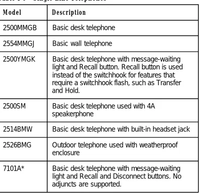
Single-Line Telephones
The system supports the single-line analog telephones listed in Table 1-6.
Note: 2500MM or 500MM telephones should be used for PFT
telephones. If the telephones are to be connected to GS lines/trunks, a GS button (KS 23566L1, PEC 31021 ) must be added to each PFT station. If rotary lines/trunks are used, PFT telephones must be rotary telephones.
Table 1-6 Single-Line Telephones
Model Description
2500MMGB Basic desk telephone 2554MMGJ Basic wall telephone
2500YMGK Basic desk telephone with message-waiting light and Recall button. Recall button is used instead of the switchhook for features that require a switchhook flash, such as Transfer and Hold.
2500SM Basic desk telephone used with 4A speakerphone
2514BMW Basic desk telephone with built-in headset jack 2526BMG Outdoor telephone used with weatherproof
enclosure
7101A* Basic desk telephone with message-waiting light and Recall and Disconnect buttons. No adjuncts are supported.
Table 1-6 Continued Model
7102A
CS6402U01A*
2500MMGJ 2500MMGK
500MM 554BMPA 500SM
Description
Basic desk telephone with message-waiting light and Recall button. No adjuncts are supported. Can be used for PFT stations. Basic desk telephone, Feature Phone Model 420. Has built-in speakerphone, memory, and redial.
Basic desk telephone
Basic desk telephone with the following limitation: Timed Recall button action (similar to a switchhook flash) will invoke the Hold and Transfer feature.
Basic telephones with the following limitations: Since these sets are equipped with rotary dials, no system features requiring ✱ and # can be used. Telephones equipped with neon message-waiting lights are not supported.
Telephones and Adjuncts Not Supported
CAUTION:
The following telephones and adjuncts cannot be used with the system. Connecting them can damage the telephones, adjuncts, and system.
Table 1-7 Telephones and Adjuncts Not Supported
Model Notes
510D Digital Communications Protocol (DCP) Personal
Terminals
DCP 7400 telephones and adjuncts (asynchronous telephones data units and multiple asynchronous data
units) that use DCP and that are supported on the MERLIN II communications system.
MET Multibutton electronic telephones (MET) and telephones adjuncts that are used with the Dimension® PBX
and Horizon® systems.
Single-line with neon message-waiting light telephones
Analog Basic telephone modem interface (BTMI); telephone BTMI-2; off-premises extension (OPX) unit; adjuncts System 25 Direct Extension Selector (DXS); DSS
System Operator Consoles
System operator consoles are telephones that are programmed for call handling and other operator duties.
Two configurations of operator consoles can be used—direct-line console (DLC) and queued call console (QCC). In a DLC configuration, lines/trunks are assigned to individual buttons and the console can have several calls ringing at the same time. In a QCC configuration, incoming calls are held in a queue and calls are directed to, a QCC as a position becomes available. Only one call rings at a time.
The following telephones can function as DLCs:
■ MLX-20L telephone* ■ MLX-28D telephone*
■ MERLIN II System Display Console with built-in DSS ■ BIS-34D
■ BIS-34 ■ BIS-22D
Note: In a Hybrid/PBX system, only the MLX-20L telephone can
function as a QCC.
Adjuncts
Adjuncts are pieces of equipment that connect directly to the CU or to a telephone through an adapter (see “Adapters” below). Answering machines, credit card verification terminals, and external alerts are examples of adjuncts. For more information on adjuncts, see Appendix B.
Adapters
Adapters enable a proper connection of equipment or, in the case of the channel service unit (CSU), of a DS1 facility to the CSU. Some adapters connect directly to the CU (system adapters) while others connect to telephones (telephone
adapters). See Chapters 3 and 6 for the installation procedures for these adapters:
■ system adapters
■ ESF T1 CSU
■ 551 T1 L1 CSU
■ Universal Paging Access Module (UPAM)
■ telephone adapters
■
■
■
Multi-Function Module (MFM) for digital telephones General Purpose Adapter (GPA) for analog telephones
■
■
ISDN 7500B Data Module for connecting digital data equipment either directly to the CU or to an MLX
System Capacities
The system comes in two sizes, large and small. The large
system supports up to 80 central office (CO) lines/trunks and 144 stations, such as telephones and fax machines, and the small system supports up to 24 CO lines/trunks and 56 stations. The size of the system is determined by its memory capacity—that is, the processor module (including the feature module) located in the control unit (CU).
The large system has a total capacity of 224 jacks (80 CO lines/trunks plus 144 stations); however, each MLX module station jack supports two logical endpoints (station devices that can operate simultaneously and independently). For example, an MLX telephone with a Multi-Function Module (MFM) plugs into only one station jack, but the jack supports the telephone and the equipment connected to the MFM (such as a fax machine or an answering machine).
In a similar way, although the 100D module has only one jack, it can serve up to 24 endpoints (emulated lines/trunks or ISDN-PRI lines/trunks).
Thus, the large system can be configured to connect up to 80 lines/trunks and 255 station endpoints, a total of 335 endpoints.
Note: The system has a time-slot capacity of 216. If more than
Table 1-8 System Capacities
Components Small Large
Carriers*
■ Total 3 3
■ Line/trunk and station module slots/basic carrier 5 5 ■ Line/trunk and station module slots/expansion carrier 6 6 ■ Maximum slots available for modules 17 17
DS1 Modules 1 3
Endpoints (devices) 56 255
Lines/Trunks 24 80
Operator Consoles
■ DLCs:
■ MLX† 6 8
■ Analog multiline‡ 8 8
■ QCCs§ 4 4
■ DSSs** 12 16
■ Combination of DLCs and QCCs 8 8 ■ Number of consoles per module 2 2 * The basic carrier contains a power supply module, processor module, and
five slots for line/trunk and station modules. Each expansion carrier contains a power supply module and six slots for Iine/trunk and station modules. † MLX-20L or MLX-28D telephone, two per MLX module
‡ MERLIN II System Display Console or 34- or 22-button analog multiline telephone with display; two per analog multiline module
§ MLX-20L telephone; two per MLX module
Table 1-8 Continued
Components Small Large
Ports (not achievable simultaneously)
■ Total (lines/trunks plus stations) 80 224 ■ Voice and data stations 56 144
■ Voice Announce to Busy 28 127 ■ Voice-mail interface 20* 20* ■ Data via ISDN 7500B Data Module 24 127
■ Paging 3 3
■ Delay announcements 32 32
System programming equipment†
■ MLX-20L 1 1
■ RS-232 jack (for connection of PC with SPM) 1 1
■ Modem 1 1
Telephones
■ Single-line 56 144
■ Analog multiline
■ Without Voice Announce to Busy 56 136 ■ Without Voice Announce to Busy 28 127
■ MLX-20L 16‡ 481‡
■ MLX with ISDN 7500B Data Module or MFM 24 127 ■ Power failure transfers 6 20
Two-party conversations 40 108
Traffic (CCS/hr/station)** 7.0 6.0
Voice-mail systems 1 1
—
* Although system software supports up to 24 voice-mail interface (VMl) ports, all the VMI ports must be in the same calling group, and the maximum number of stations in a calling group is 20.
† Remote access overrides on-site programming except during backup or
restore
‡ Total includes the MLX-20L telephone used for system programming § One per four GS/LS line/trunk jacks
Table 1-9 lists the capacities for features.
Table 1-9 Feature Capacities
Feature Description Maximum
Allowed Number of lists 8
Lists Entries per list 10
Digits per entry 7
ARS Number of ARS patterns 18
Subpatterns per pattern 2 Routes per subpattern 6 Number of fully programmable
ARS tables 16
Entries per table 100
Entries across all tables 1600
Default tables 4
Callback Number of calls in queue 64
Calling Number of groups 32
Groups Members per group* 20
Groups per member 1
Delay announcements per system 32 Delay announcements per group 1 Groups per delay announcement 32 External alerts per group 1 Coverage groups per group 1
Coverage Number of groups 30
Groups Senders per group 56 (small) 144 (large)
Groups per sender 1
Table 1-9 Continued
Feature Description Maximum
Data Hunt Number of groups 32
Groups Members per group 20
Groups per member 1
DID Number of blocks 2
Number of trunks 24 (small) 80 (large) Directories System Directory
■ Number per system ■ Listings per directory
Extension Directory
■ Number per system ■ Listings per directory
Personal Directory
■ Number per system ■ Listings per directory
1 40 (small) 130 (large)
1 56 (small) 144 (large)
16 (small) 48 (large)