T1 Data Service Unit with
Frame Relay Performance Monitoring
User Manual
61200215L1-1D
1200215L1 TSU IQ Unit 1204005L1 Ethernet Card
1204001L1 4-wire SW56 DBU Card
1204002L1 V.34 DBU Card
1204004L1 ISDN DBU Card
1204006L1 External DCE Card
1204008L1 PRI DBU Card
OpenView is a trademark of Hewlett-Packard Company.
SunNet Manager is a registered trademark of Sun Microsystems, Inc. Netview is a registered trademark of IBM.
IQ View is a trademark of ADTRAN, Inc.
This product includes software developed by the University of California, Berkeley, and its contributors.
901 Explorer Boulevard P.O. Box 140000 Huntsville, AL 35814-4000
Phone: (256) 963-8000
© 2000 ADTRAN, Inc. All rights reserved.
Notes provide additional useful information.
Cautions signify information that could prevent service interrup-tion.
1. This equipment complies with Part 68 of the FCC rules. On the bottom of the equipment housing is a label that shows the FCC registration number and Ringer Equivalence Number (REN) for this equipment, if applicable. If required, this information must be given to the telephone company.
2. The following information may be required when applying to the local telephone company for leased line facilities.
3. An FCC compliant telephone cord with a modular plug may be provided with this equipment. This equipment is designed to be connected to the telephone net-work or premises wiring using a compatible modular jack, which is FCC Part 68 compliant. See installation instructions for details.
4. If this equipmentcauses harm to the telephone network, the telephone company may temporarily discontinue service. If possible, advance notification is given; otherwise, notification is given as soon as possible. The telephone company will advise the customer of the right to file a complaint with the FCC.
5. The telephone company may make changes in its facilities, equipment, opera-tions, or procedures that could affect the proper operation of this equipment. If this happens, the telephone company will provide advance notification and the opportunity to make the necessary modifications to maintain uninterrupted ser-vice.
6. If experiencing difficulty with this equipment,please contact ADTRANfor repair and warranty information. If the equipment is causing harm to the network, the telephone company may request this equipment to be disconnected from the net-work until the problem is resolved or it is certain that the equipment is not mal-functioning.
7. This unit contains no user-serviceable parts.
8. The FCC recommends that the AC outlet, to which equipment requiring AC power is to be installed, is provided with an AC surge arrester.
Service Type REN/SOC FIC USOC
MBPS and/or Subrate Digital Services
For the work to be performed in the certified territory of ______________ (telco name)
State of ________________________________
County of ______________________________
I, _______________________ (name), ____________________ (business address), _____________________ (telephone number) being duly sworn, state:
I have the responsibility for the operation and maintenance of the terminal equipment to be connected to 1.544 Mbps and/or __________________ subrate digital services. The terminal equipment to be connected complies with Part 68 of the FCC rules except for the encoded analog content and billing protection specification.
With respect to encoded analog content and billing protection:
( ) I attest that all operations associated with the establishment, maintenance and adjustment of the digital CPE with respect to encoded analog content and billing pro-tection information continuously complies with Part 68 of the FCC rules and Regula-tions.
( ) The digital CPE does not transmit digital signals containing encoded analog con-tent or billing information which is intended to be decoded within the telecommuni-cations network.
( ) The encoded analog content and billing protection is factory set and is not under the control of the customer.
I attest that the operator(s) maintainer(s) of the digital CPE responsible for the estab-lishment, maintenance and adjustment of the encoded analog content and billing information has (have) been trained to perform these functions by successfully having completed one of the following (check appropriate blocks):
( ) C. An independent training course (e.g., trade school or technical institution) rec-ognized by the manufacturer/grantee of the equipment used to encode analog sig-nals; or
( ) D. In lieu of the proceeding training requirements, the operator(s)/maintainer(S) is (are) under the control of a supervisor trained in accordance with _______________ (circle one) above.
I agree to provide ____________________ (telco’s name) with proper documentation to demonstrate compliance with the information in the preceding paragraph, if so requested.
_____________________ Signature
_____________________ Title
_____________________ Date
Subscribed and sworn to before me
This _________ day of ___________________, 20__
_______________________________________ Notary Public
• An affidavit is required to be given to the telephone company whenever digital terminal equipment without encoded analog content and billing protection is used to transmit digital signals containing encoded analog content which are intended for eventual conversion into voice band analog signal and transmitted on the network.
• The affidavit shall affirm that either no encoded analog content or billing informa-tion is being transmitted or that the output of the device meets Part 68 encoded analog content or billing protection specification.
• End use/customer will be responsible to file an affidavit with the local exchange carrier when connecting unprotected CPE to a 1.544 Mbps or subrate digital ser-vice.
Radio Frequency Interference Statement
This equipment has been tested and found to comply with the limits for a Class A dig-ital device, pursuant to Part 15 of the FCC Rules. These limits are designed to provide reasonable protection against harmful interference when the equipment is operated in a commercial environment. This equipment generates, uses, and can radiate radio fre-quency energy and, if not installed and used in accordance with the instruction man-ual, may cause harmful interference to radio frequencies. Operation of this equipment in a residential area is likely to cause harmful interference in which case the user will be required to correct the interference at his own expense
.
Canadian Emissions Requirements
This digital apparatus does not exceed the Class A limits for radio noise emissions from digital apparatus as set out in the interference-causing equipment standard enti-tled “Digital Apparatus,” ICES-003 of the Department of Communications.
Cet appareil nuerique respecte les limites de bruits radioelectriques applicables aux appareils numeriques de Class A prescrites dans la norme sur le materiel brouilleur: “Appareils Numeriques,” NMB-003 edictee par le ministre des Communications.
Shielded cables must be used with this unit to ensure compliance with Class A FCC limits.
Notice: The Canadian Industry and Science Canada label identifies certified equip-ment. This certification means that the equipment meets certain telecommunications network protective, operational, and safety requirements. The Department does not guarantee the equipment will operate to the user’s satisfaction.
Before installing this equipment, users should ensure that it is permissible to be con-nected to the facilities of the local telecommunications company. The equipment must also be installed using an acceptable methods of connection. In some cases, the com-pany’s inside wiring associated with a single line individual service may be extended by means of a certified connector assembly (telephone extension cord). The customer should be aware that compliance with the above limitations may not prevent degra-dation of service in some situations.
Repairs to certified equipment should be made by an authorized Canadian mainte-nance facility designated by the supplier. Any repairs or alterations made by the user to this equipment, or equipment malfunctions, may give the telecommunications company cause to request the user to disconnect the equipment.
Users should ensure for their own protection that the electrical ground connections of the power utility, telephone lines and internal metallic water pipe system, if present, are connected together. This precaution may be particularly important in rural areas.
The Load Number (LN) assigned to each terminal device denotes the percentage of the total load to be connected to a telephone loop which is used by the device, to pre-vent overloading. The termination on a loop may consist of any combination of devices subject only to the requirement that the total of the Load Numbers of all devices does not exceed 100.
When using your telephone equipment, please follow these basic safety precautions to reduce the risk of fire, electrical shock, or personal injury:
1. Do not use this product near water, such as near a bath tub, wash bowl, kitchen sink, laundry tub, in a wet basement, or near a swimming pool.
2. Avoid using a telephone (other than a cordless-type) during an electrical storm. There is a remote risk of shock from lightning.
3. Do not use the telephone to report a gas leak in the vicinity of the leak.
4. Use only the power cord, power supply, and/or batteries indicated in the manual. Do not dispose of batteries in a fire. They may explode. Check with local codes for special disposal instructions.
Save These Instructions
Warranty and Customer Service
ADTRAN will replace or repair this product within five years from the date of ship-ment if it does not meet its published specifications or fails while in service. For detailed warranty, repair, and return information refer to the ADTRAN Equipment Warranty and Repair and Return Policy Procedure.
ADTRAN warrants that for five (5) years from the date of shipment to Customer, all products manufactured by ADTRAN will be free from defects in materials and workmanship. ADTRAN also warrants that products will conform to the applicable specifications and drawings for such products, as contained in the Product Manual or in ADTRAN's internal specifications and drawings for such products (which may or may not be reflected in the Product Manual). This warranty only applies if Customer gives ADTRAN written notice of defects during the warranty period. Upon such notice, ADTRAN will, at its option, either repair or replace the defective item. If ADTRAN is unable, in a reasonable time, to repair or replace any equipment to a condition as warranted, Customer is entitled to a full refund of the purchase price upon return of the equipment to ADTRAN. This warranty applies only to the original purchaser and is not transferable without ADTRAN's express written permission. This warranty becomes null and void if Customer modifies or alters the equipment in any way, other than as specifically authorized by ADTRAN.
EXCEPT FOR THE LIMITED WARRANTY DESCRIBED ABOVE, THE FOREGOING CONSTITUTES THE SOLE AND EXCLUSIVE REMEDY OF THE CUSTOMER AND THE EXCLUSIVE LIABILITY OF ADTRAN AND IS IN LIEU OF ANY AND ALL OTHER WARRANTIES (EXPRESSED OR IMPLIED). ADTRAN SPECIFICALLY DIS-CLAIMS ALL OTHER WARRANTIES, INCLUDING (WITHOUT LIMITATION), ALL WARRANTIES OF MERCHANTABILITY AND FITNESS FOR A PARTICULAR PURPOSE. SOME STATES DO NOT ALLOW THE EXCLUSION OF IMPLIED WAR-RANTIES, SO THIS EXCLUSION MAY NOT APPLY TO CUSTOMER.
List of Figures ...xxvii List of Tables ... xxix Chapter 1. Introduction
Product overview ... 1-1 Features ... 1-2 Understanding Frame Relay ... 1-3 T1/FT1 Overview ... 1-4 T1 Service Offerings... 1-4 Fractional T1 ... 1-4 SNMP Management ... 1-5 Network Manager ... 1-5 Agent ... 1-5 MIB ... 1-5 Telnet ... 1-6 Dial Backup Operation... 1-6 Interface Card Options ... 1-6 Ethernet Card... 1-6 4-Wire Switched 56 DBU Card... 1-7 V.34 DBU Card ... 1-7 ISDN DBU Card ... 1-7 PRI DBU Card... 1-7 DCE Card ... 1-7
Chapter 2. Installation
Power Up... 2-2 Rear Panel ... 2-3 DBU and LAN Card Slots ... 2-4 Network Connector: Network Interface Connection... 2-4 Test Jacks ... 2-4 Monitor ... 2-4 In/Out ... 2-4 Control Port... 2-5 V.35 Connector: DTE Data Connection... 2-5
Chapter 3. Operation
Chapter 4. Applications
DBU Application 2 - PRI ... 4-14
Chapter 5. Configuration Overview
Local and Remote Configuration ... 5-1
Chapter 6. DTE Port Configuration
Physical Layer Options (PHYS LYR OPT)... 6-2 Flow Control ... 6-2 None ... 6-2 Hardware ... 6-2 FECN/BECN ... 6-3 CTS Option ... 6-3 Forced On ... 6-3 Follow RTS ... 6-3 DSR Option ... 6-3 Forced On ... 6-3 Normal ... 6-3 CD Option ... 6-3 Forced On ... 6-3 Normal ... 6-3 TC Clock Option (TC CLOCK OPT) ... 6-3 Normal ... 6-3 Inverted ... 6-4 Frame Relay Options (FR OPTS)... 6-4 T392 ... 6-4 N392 and N393 ... 6-4 Management DLCI (MGMT DLCI) ... 6-5 Guidelines for Configuring Management DLCI ... 6-5 Management PVC Option (MGMT PVC OPT) ... 6-5 Signaling Responses (SIG RESPONSES) ... 6-5 Always On ... 6-5 Follow Network (FOLLOW NET) ... 6-5 Always Off ... 6-5
Chapter 7. Network Port Configuration
Rx Sensitivity (RX GAIN) ... 7-3 Channel Bandwidth (CHANNEL RATE) ... 7-3 Channel Alignment (CHANNEL ALIGN) ... 7-3 Start Channel (1ST CHANNEL) ... 7-3 Number of Channels (#OF CHANNELS) ... 7-4 Transmit PRM ... 7-4 Frame Relay Options (FR OPT) ... 7-4 Signaling Type (SIGNAL) ... 7-5 T391 ... 7-5 N391 ... 7-5 N392 and N393 ... 7-5 Management DLCI 1 and 2 (DLCI 1 and 2) ... 7-6 Management DLCI 1 and 2 Mode (DLCI 1 and 2 MODE)... 7-6 Max PVC Count ... 7-6 History Interval Count (HIST INT COUNT) ... 7-6 PVC Options (PVC CONFIG) ... 7-7 DLCI ... 7-7 DBU DLCI ... 7-7 DBU Phone Number ... 7-7 DBU on Inactive ... 7-7 DBU Call Order # ... 7-8 CIR (Kbps) ... 7-8 Seq Num Checking (SEQ #) ... 7-8 Delay Measurement (PVC DELAY) ... 7-8 Stats Option (STATS OPT) ... 7-9 Auto ... 7-9 Enabled ... 7-9 Disabled ... 7-9 Next (NEXT key on front panel) ... 7-9 Previous (PREV key on front panel) ... 7-9 Add (ADD key on front panel) ... 7-9 Delete (DELETE key on front panel) ... 7-9
Chapter 8. Configuring DBU Options
Chapter 9. System Configuration
Change Password ... 9-1 IP Address... 9-1 Subnet Mask... 9-1 IP Address (IP ADDRESS)... 9-2 Control Port Mode (CNTL PORT MODE) ... 9-2 Read Community Name (RD COM NAME) ... 9-2 Write Community Name (WR COM NAME) ... 9-3 Trap Mgr Options ... 9-3 Trap Manager DLCI (TRAP DLCI) ... 9-3 Trap Manager IP Address (TRAP IP) ... 9-3 Trap Manager Port (TRAP PORT) ... 9-3 Next (NEXT key on front panel) ... 9-3 Previous (PREV key on front panel) ... 9-3 Add (ADD key on front panel) ... 9-3 Delete (DELETE key on front panel) ... 9-4 Protocols 1 and 2 ... 9-4 System Name ... 9-5 System Time/Date ... 9-5 History Interval Size (HIS INT SIZE)... 9-5 Using the Front Panel ... 9-6
Chapter 10. Statistics
CRC Errors ... 10-32 Abort Frames ... 10-32 Octet Align ... 10-32 Signal Down Time ... 10-32 Network Port Statistics Available on Front Panel ... 10-33 TSU Loop State ... 10-33 PRI Loop State ... 10-33 DBU Status ... 10-33 Signal State ... 10-33 Signal State Change ... 10-33 Signal Timeouts ... 10-33 Signal Errors ... 10-33 Frames In ... 10-33 Frames Out ... 10-33 Errored Frames ... 10-33 CRC Errors ... 10-33 Abort Frames ... 10-33 Octet Align ... 10-33 Port UA Time ... 10-34 Line Code ... 10-34 Path Code ... 10-34 DBU Port Statistics Available on Front Panel ... 10-34 PRI Loop State ... 10-34 D Channel State ... 10-34 DBU Status ... 10-34 Time in DBU ... 10-34 Frames In ... 10-34 Frames Out ... 10-34 Errored Frames ... 10-34 CRC Errors ... 10-34 Abort Frames ... 10-35 Octet Align ... 10-35 System Statistics Available on Front Panel ... 10-35
Chapter 11. Testing
Max Response Time (MAX RESP TIME) ... 11-3 Avg Response Time (AVG RESP TIME) ... 11-3 PVC Loopback ... 11-4 DLCI or 0 for All (DLCI) ... 11-4 Test Length ... 11-4 Start Test ... 11-4 Stop Test ... 11-5 View Test ... 11-5 PVC Active/Inactive/Undefined ... 11-5 Test Active/No Test Active ... 11-5 Frames Rx ... 11-5 Frames Tx ... 11-5 Lost Frames ... 11-5 Remote Lost Frames ... 11-5 Minimum Loop Response Time (MIN RESP TIME) ... 11-5 Maximum Loop Response Time (MAX RESP TIME) ... 11-5 Average Loop Response Time (AVG RESP TIME) ... 11-6 Reset Test Stats ... 11-6 View DLCI List ... 11-6
Chapter 12. Activating Dialing Functions
Dialing Options ... 12-1 Dial Options when Dial Backup is Idle... 12-2 Dial Backup ... 12-2 Stay on Leased ... 12-2 Dial Options During Dial Backup ... 12-2 Dial Backup ... 12-2
PRODUCT OVERVIEW
The ADTRAN TSU IQ provides the visibility and control needed for both the physical and logical connections made in frame relay networks. The TSU IQ provides logical layer monitoring and management for frame relay. Each permanent virtual circuit (PVC) accessed through a TSU IQ is managed end-to-end as if it were a leased line connection. Real-time statistics on throughput, bandwidth utilization, availability, bursting, congestion, and network delay are collected and stored in the Frame IQ MIB (management information base). This information can then be gathered by management systems and used to monitor network health and perform long-term network planning.
The unit's embedded SNMP (simple network management
Features
Features of the TSU IQ are:
• Complete and comprehensive frame relay monitoring, including Layer 3 Protocol monitoring.
• Real-time measurement of bandwidth utilization, committed information rates (CIRs), and excess burst rates on each PVC. • True non-intrusive, in-band transmission of statistics.
• Embedded SNMP and Telnet through the DTE, network, or SLIP/PPP port (or through the optional ethernet interface). • Control port provides SLIP and async PPP access to SNMP or
VT 100 terminal configuration.
• Dial backup (DBU) is available with DBU cards; options include 4-wire Switched 56 (SW56), V.34, PRI, and ISDN. • End-to-end network round trip delay measurements for
network optimization.
• 10BaseT ethernet port available with ethernet card. • Frame IQ MIB is standard ANSI format compatible with
popular enterprise reporting systems.
• Optional IQ View™ software system provides a cost-effective, easy-to-use GUI (graphical user interface) for performance management.
• Standard DTE (data terminal equipment) interfaces.
The 4-wire SW56 DBU card is compatible with AT&T Accunet and Sprint SW56 type services.
The V.34 DBU card allows switched backup over the public switched telephone network (PSTN).
The ISDN 1B+D card supports a U-interface to the Basic Rate ISDN and is compatible with National ISDN and AT&T DMS.
The PRI DBU card allows the TSU IQ to accept or place up to 23 dial backup calls simultaneously.
UNDERSTANDING FRAME RELAY
Frame relay is a wide area network (WAN) service designed to minimize physical connections. This is accomplished by using virtual connections within the frame relay cloud and accessing these virtual circuits with normally one physical connection at each location to the frame relay service. Virtual circuits are addressed using header information at the beginning of each frame. These frames are formatted by the user's customer premises equipment (CPE) such as the ADTRAN TSU IQ.
ANSI (American National Standards Institute) standards describe how each frame must be constructed to provide interoperability between CPE equipment and frame relay switching equipment. Each frame must contain a header, at least one byte of information data, two bytes of CRC16, and a trailing flag 0x7E.
This header information contains a virtual circuit address known as a DLCI (data link connection identifier). The header information also contains bits used for network congestion control.
T1/FT1 OVERVIEW
The telephone companies (telcos) have used T1 digital
communications links for voice transmission since the early sixties. The D4 channel bank is an example of a T1 digital carrier system that was introduced in the mid-seventies and is still widely used by the telcos. Communication demands of businesses continued to grow to the point that the telcos began offering T1 service directly to the public. D4 channel banks began to be used for T1 in corporate network topographies for voice. The technological advances in computer development also created a demand for T1 data communication which now is a large part of the T1 traffic.
T1 Service Offerings
T1 is a digital service that the service providers deliver to the user over two pairs of wires. The signal operates at 1.544 Mbps and is usually extended by repeaters that are installed about every mile after the first 6000 feet. The T1 signal is divided into 24 time slots or digital signal level zeros (DS0s) which operate at 64 kbps. Each time slot is occupied by digitized voice or by data.
The T1 signal originally used a type of framing known as D4 superframe which identifies how the T1 is multiplexed. Extended superframe (ESF) is an enhancement of that framing format. ESF provides a non-disruptive means of full-time monitoring on the facility datalink (FDL). The service providers originally used ESF to monitor the performance of their service offering. Since the introduction of ESF, equipment that is installed in private networks can also provide the same performance information to the user.
Fractional T1
Fractional T1 (FT1) lets the buyer purchase less than a full T1 circuit between two points. Most carriers offer fractional T1 in increments of 56 or 64 kbps. Connection is made to the same network
FT1 remains almost exclusively an inter-exchange carrier (IXC) service. Local exchange carriers (LECs) typically do not offer FT1, so the user's proximity to the IXC's point-of-presence (POP) is key in the savings that fractional T1 offers.
SNMP MANAGEMENT
SNMP management capability is provided in-band with support for ,RFC 1315 (frame relay DTE MIB), ,RFC 1213 (MIB II), RFC 1406 (DS1/E1 MIB), and ADTRAN Enterprise MIB. MIB files are available from ADTRAN in the support section of the ADTRAN web page at www.adtran.com. Telnet capability is also supported. For non-SNMP environments, VT 100 and front panel operation are supported.
The TSU IQ's embedded SNMP feature allows the unit to be accessed and controlled by a network manager in-band at the DTE or network interface, out-of-band at the control port via SLIP or async PPP, or using a LAN connection. LAN connection requires the optional ethernet card (P/N 1204005L1). This card provides a 10BaseT ethernet interface to the LAN.
The term SNMP broadly refers to the message protocols used to exchange information between the network and the managed devices, as well as to the structure of network management data bases. The three basic components of SNMP follow.
Network Manager
Control program that collects, controls, and presents data pertinent to the operation of the network devices. It resides on a network management station.
Agent
Control program that resides in each connected network device. This program responds to queries and commands from the network manager and returns requested information or invokes configuration changes initiated by the manager.
MIB
TELNET
Telnet provides a password-protected, remote login facility to the TSU IQ. Telnet allows a user on a network manager to control the TSU IQ through the terminal menus.
Dial Backup Operation
The TSU IQ dial backup (DBU) option cards provide single or multiple site backup, depending on the DBU card option selected. The TSU IQ can be configured to originate a call based on physical layer conditions (i.e., port failures)and/or PVC outages. Once the criteria are met, the TSU IQ establishes a call to the configured phone number and the connection is used to carry traffic for the PVC(s) configured for DBU operation.
In the case of PVC outages (not physical layer port failure), the TSU IQ's two-port design allows the TSU IQ receiving the call to continue to use the T1 frame relay circuit for PVCs that are not affected by the outage, while using the DBU interface for PVCs that are inactive due to the outage. A TSU IQ with multiple PVCs to multiple sites can also originate a call to one site during an outage and restore connection for PVCs to that destination.
The TSU IQ's unique DBU cards are field-installable by the customer. See Installation on page 2-1 for information on installing DBU cards. The DBU cards are compatible with other ADTRAN products supporting dial backup. The backup options are described in the following section, Interface Card Options. Contact the local telco provider to determine which services are available in your area. See Applications on page 4-1 for more information, including examples of a dial backup application.
INTERFACE CARD OPTIONS
Ethernet Card
This option card connects to an ethernet LAN, providing
4-Wire Switched 56 DBU Card
This dial-up 4-wire SW56 card allows you to pay for data connection only for the time the unit is active. The regional
operating companies provide the 4-wire local loop service to SW56 customers. The 4-wire SW56 DBU card is compatible with AT&T Accunet and Sprint SW56 type services.
V.34 DBU Card
The V.34 DBU card provides switched backup of the leased line application. This module allows backup data rates of up to 33.6 kbps over the PSTN.
ISDN DBU Card
The ISDN 1B+D card supports a U-interface to the Basic Rate ISDN and is compatible with National ISDN and AT&T DMS. 1B+D Basic Rate ISDN service provides a switched 56/64 kbps circuit.
PRI DBU Card
The PRI DBU 23 B+D (primary rate interface dial backup) card allows the TSU IQ to accept or place up to 23 dial backup calls simultaneously. This card supports 64kbps data service. Incoming calls will be accepted for 56kbps or 64kbps service. Bonding is not supported. Fractional PRI capability is supported.
DCE Card
UNPACK, INSPECT, POWER UP
Receipt Inspection
Carefully inspect the TSU IQ for any shipping damage. If damage is suspected, file a claim immediately with the carrier and contact ADTRAN Customer Service (see the back page for more
information). If possible, keep the original shipping container for use in shipping the TSU IQ for repair or for verification of damage during shipment.
ADTRAN Shipments Include
The following items are included in ADTRAN shipments of the TSU IQ:
• TSU IQ unit • The user manual
• An 8-position modular to 8-position modular cable • An 8-position modular to 8-position modular cable and a
modular-to-female DB-9 adapter for access to the Control/ SLIP/PPP port
The following items are included in ADTRAN shipments of DBU cards:
• DBU card
• An 8-position modular to 8-position modular cable for the 4-wire SW56 and ISDN DBU options or an 8-position modular to 4-position modular cable for the V.34 DBU option
Customer Provides
The customer must provide a male V.35 interface cable.
For SNMP management not accessed through the DTE or network port, the customer must provide access to the TSU IQ either through a SLIP port, Async PPP port (requires a male 25-pin D-type connector), or a 10BaseT ethernet port (requires that an ADTRAN Ethernet card be installed in the TSU IQ). See Pinouts on page A-1 for the pin assignments of the control port (for SLIP and Async PPP) and the ethernet port.
Power Up
The TSU IQ is provided with a captive 8-foot power cord, terminated by a three-prong plug which connects to a grounded 115 VAC power receptacle.
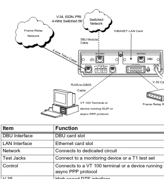
REAR PANEL
The rear panel contains a DTE connector which provides primary channel V.35. An 8-pin network jack, test jacks, a control port, a captive power cord, and a power switch are also located on the rear panel. Pin assignments for these connectors are listed in Pinouts on page A-1. The TSU IQ rear panel is shown in Figure 2-1 with optional DBU and ethernet cards installed.
Item Function
DBU Interface DBU card slot
LAN Interface Ethernet card slot
Network Connects to dedicated circuit
Test Jacks Connect to a monitoring device or a T1 test set
Control Connects to a VT 100 terminal or a device running SLIP or
async PPP protocol
V.35 High speed DTE interface
Power Switch Turns power on or off
115 VAC Connection Power cord connection
Frame Relay Network
VT 100 Terminal or device running SLIP or async PPP protocol
Frame Relay Router or FRAD
4-wire Telco Cable
RJ45-to-DB25 Cable
V.35 Cable 10BASET LAN Card
NETWORK
INOUT
TEST JACKS CONTROL V.35 NX56/64
MON
DBU INTERFACE LAN INTERFACE
10 BASE T ETHERNET 115 VAC 60HZ.15A ON OFF DBU TELCO
V.34, ISDN, PRI 4-Wire Switched 56
DBU Modular Cable
DBU and LAN Card Slots
The TSU IQ rear panel has two card slots (labeled DBUINTERFACE
and LAN INTERFACE) for the installation of dial backup, ethernet, and DCE cards. To insert cards, perform the following procedure:
1. Turn off the power switch on the rear panel.
2. Slide the card into the corresponding rear slot until the card panel is flush with the TSU IQ chassis.
3. Push card locks in (until they click) to secure the card and ensure proper installation.
Network Connector: Network Interface Connection
Connect the TSU IQ to the network by using the 8-position modular jack labeled NETWORK. The pinout for this connector is listed in Pinouts on page A-1.
Test Jacks
Monitor
The monitor jack (labeled MON) is used as a non-intrusive monitoring point for the data received from the network. The monitoring device needs to be set for high impedance bridge mode.
In/Out
The INand OUTjacks are used to connect to a T1 test set for testing the T1 interface of the TSU IQ. These connections isolate the T1 interface from the RJ-45 telco (network) jack.
Card slots are keyed to prevent improper installation (i.e., putting a DBU card into the ethernet slot). The DCE card is keyed for the DBU slot.
Control Port
The TSU IQ has an 8-pin modular jack labeled CONTROL. The control port provides connection to a VT 100 EIA-232-compatible interface, a device running SLIP protocol, or a device running Async PPP protocol. An 8-foot cable with adapter connector provides a standard DB-25 EIA-232 interface. See Pinouts on page A-1 for the control port’s pin assignments. A description of the operation of this port is covered in Operation on page 3-1.
V.35 Connector: DTE Data Connection
The DTE should be connected to the V.35 connector (labeled V.35 NX56/64). The maximum cable length is 100 feet. The pin assignments for this connector are listed in Pinouts on page A-1.
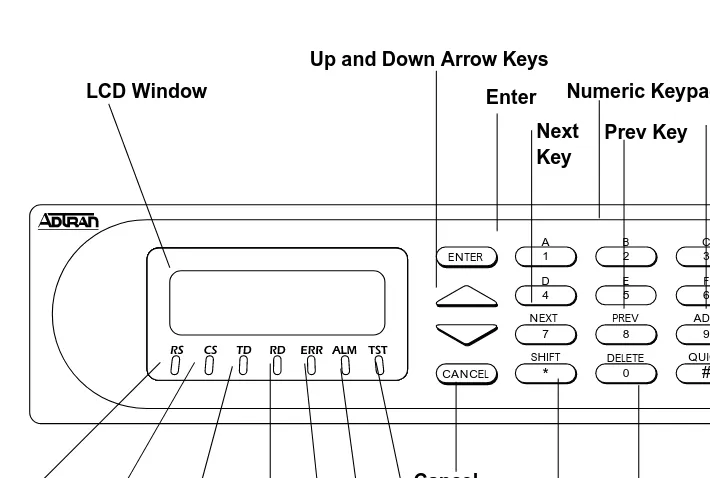
FRONT PANEL
The TSU IQ faceplate is shown in Figure 3-1. Descriptions of each part of the front panel follow.
Add Key
RS LED
TST LED LCD Window
Up and Down Arrow Keys
Enter Numeric Keypad
Cancel
Shift Delete Quick Key
Prev Key CS LED TD LED RD LED ALM ERR Next Key SHIFT * 7 D 4 A 1 8 0 E 5 B 2 QUICK TSU IQ # 9 F 6 C 3 ENTER CANCEL
NEXT PREV ADD
LCD Window
Displays menu items and messages in 2 lines by 16 characters.
Enter
Selects active menu items. To activate a menu item, scroll to it using the arrow keys or press the number of the item. The flashing cursor indicates the active parameter. Press Enterto select the active menu item.
Up and Down Arrows
The up and down arrows scroll through and activate the menu items of the current menu. The flashing cursor indicates the active parameter.
Cancel Key
Pressing the Cancel key stops the current activity and returns to the previous menu. Repeat until the desired menu level is reached. When a submenu item is displayed, press Cancel to exit the current display and return to the previous menu.
Quick Key
Pressing the Quickkey returns the front panel to the main menu.
Numeric Keypad
The numeric keypad contains the numbers 0 through 9 and alpha characters A through F, which are used to activate menu items and enter information such as the IP address.
Next, Prev, Add, Delete Keys
To activate these functions, press and release the Shift key; then press the Next, Prev, Add, orDelete key. Use these keys when editing tables such as the PVC Options table. See PVC Options
Shift Key
Enter alpha characters by first pressing and releasing theShiftkey and then pressingthe desired character. The Next, Prev, Add, and
Deletekeys are also activated by first pressingShift.
To activate a menu item designated by an alpha character rather than a number, place the cursor on the menu item using the up and down arrows or press Shift and then the letter. The flashing cursor indicates the active parameter. Press Enterto select the item.
LED Descriptions
The TSU IQ has seven LED indicators: RS, CS, TD, RD, ERR, ALM, and TST. These LEDs are identified as follows:
RS: Request to Send
Reflects the status of the RS pin of the DTE interface.
CS: Clear to Send
Reflects the status of the CS pin of the DTE interface.
TD: Transmit Data
This LED is active when the TSU IQ DTE port is transmitting data.
RD: Receive Data
This LED is active when the TSU IQ DTE port is receiving data.
ERR: Error
This LED is active when a T1 line code violation or a T1 path code violation occurs.
ALM: Alarm
This LED is active when an alarm condition exists. Alarm conditions include:
T1 Alarm Conditions • Loss of signal
• Loss of T1 frame sync (red alarm)
• Receiving AIS (alarm indication signal) from the service provider
Frame Relay Alarm Condition
TST: Test
This LED is active when the network interface is in a loopback condition triggered from the service provider.
Front Panel Operation
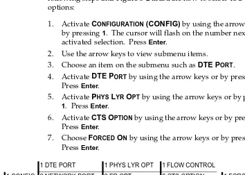
To choose a menu item, press the corresponding number or alpha character on the keypad. Press Shift to activate menu items with alpha selections. Scrolling to the selection by pressing the up and down arrows also activates the menu items. The flashing cursor indicates the active selection. Press Enter to select the item. The following steps and Figure 3-2 illustrate how to select TSU IQ options:
1. Activate CONFIGURATION (CONFIG) by using the arrow keys or by pressing 1. The cursor will flash on the number next to the activated selection. Press Enter.
2. Use the arrow keys to view submenu items.
3. Choose an item on the submenu such as DTE PORT.
4. Activate DTE PORT by using the arrow keys or by pressing 1. Press Enter.
5. Activate PHYS LYR OPT by using the arrow keys or by pressing
1. Press Enter.
6. Activate CTSOPTIONby using the arrow keys or by pressing 2. Press Enter.
7. Choose FORCED ON by using the arrow keys or by pressing 1. Press Enter.
Figure 3-2. Example of Basic Front Panel Menu Navigation
1 DTE PORT 1 PHYS LYR OPT 1 FLOW CONTROL
1 CONFIG 2 NETWORK PORT 2 FR OPT 2 CTS OPTION 1 FORCED ON
3 CONTROL PORT 3 DSR OPTION 2 FOLLOW RTS
4 SYSTEM 4 CD OPTION
VT-100 Terminal Connection and Operation
To control the TSU IQ using a VT 100 terminal, follow this procedure:
1. Set the TSU IQ baud rate to match the terminal through the front panel (maximum rate is 38.4k). Select 1 CONFIG, then select 3 CONTROL PORT.
2. Using the ADTRAN-provided VT 100 terminal adapter, connect the COM port of a VT 100 compatible terminal or equivalent to the eight-pin modular jack labeled CONTROLon the rear of the TSU IQ. This connection is used for both local and remote configuration.
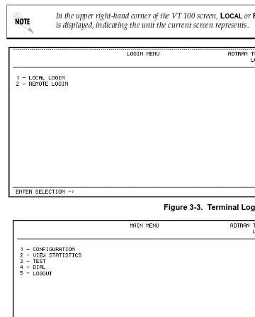
3. Open the connection and press Enter repeatedly until the LOGIN
menu appears (Figure 3-3 on page 3-6).
4. Select LOCAL LOGIN to configure the TSU IQ unit connected to
the terminal.
5. Select REMOTE LOGIN to configure a remotely located TSU IQ unit.
6. For remote applications, at the remote DLCI prompt, enter the outgoing DLCI (see the following note) by pressing 1, then
Enter, entering the DLCI number, and pressing Enter again.
7. Select BEGIN REMOTE SESSION by pressing 2 and Enter.
8. Enter the password. The factory default password is adtran. The main menu will appear (Figure 3-4 on page 3-6).
9. Make selections by entering the number corresponding to the chosen parameter. Press ESC to return to the previous screen.
When entering the DLCI for a remote application, enter the DLCI associ-ated with the local unit that you are logged in to (not the far end DLCI).
If the wrong DLCI is entered or a network problem exists, the screen
freez-es at the PRESSANYKEYTOCONTINUE prompt. Press CNTL + L twice
Figure 3-3. Terminal Login Menu
Figure 3-4. Terminal Main Menu
In the upper right-hand corner of the VT 100 screen, LOCALor REMOTE
TELNET
Local Login Via Telnet
Before you begin, please note the following:
Figure 3-5. PC Connected to Local and Remote IQs
Local Login via Telnet is defined as telnetting from the PC into IQ #1 and then choosing LOCAL LOGIN to enter the main menu of IQ # 1 and begin configuration of that unit, as shown in Figure 3-5.
Only one Telnet session can be active at one time.
The Telnet session will time-out after 5 minutes of inactivity.
IQ #1 FR
PC
DLCI 16 DLCI 17
IP 200.200.250.1
IQ #2
Mask 255.255.255.0 IP 200.200.200.2
Mask 255.255.255.0
To connect to the TSU IQ(s) via Telnet, follow these steps:
1. Before attempting to connect via Telnet to IQ unit #1, define the
IP ADDRESS, the GATEWAY IP ADDRESS, and the SUBNET MASK
using the front panel. These options are under SYSTEM CONFIG. 2. When you begin the local login via Telnet session into IQ #1,
you will see the screen shown in Figure 3-6.
Figure 3-6. TSU IQ Login Screen (Local)
ADTRAN TSUIQ VER 3.31 2779
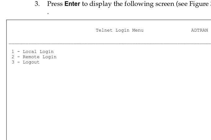
3. Press the Enterkey to display following screen. See Figure 3-7.
Figure 3-7. Telnet Login Menu Screen (Local)
4. To login to the local unit (i.e., the unit you are telnetted into), choose 1 for LOCAL LOGIN and press Enter.
5. Next you will be prompted for a password. The default password is adtran.
Telnet Login Menu ADTRAN TSUIQ Telnet _______________________________________________________________________________
1 - Local Login 2 - Remote Login 3 - Logout
_______________________________________________________________________________ Enter Selection ->
You can change this password using the SYSTEM CONFIG submenu. This
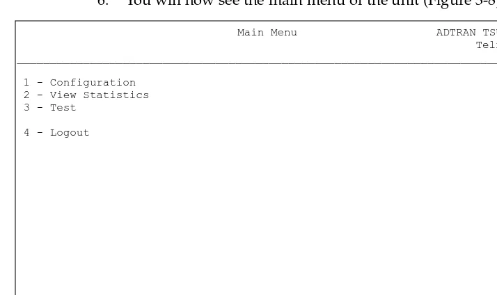
6. You will now see the main menu of the unit (Figure 3-8).
Figure 3-8. TSU IQ Main Menu Screen
7. Notice that when you are telnetted into the local unit, the word
Telnet will appear in the upper right-hand corner.
Main Menu ADTRAN TSU IQ Telnet _______________________________________________________________________________
1 - Configuration 2 - View Statistics 3 - Test
4 - Logout
Remote Login Via Telnet
Remote Login via Telnet is defined as telnetting from the PC into IQ #1 and then choosing REMOTE LOGIN to enter the main menu of IQ #2 and begin configuration of that unit.
1. Before attempting to connect via Telnet to IQ Unit #2, define the
IP ADDRESS, the GATEWAY IP ADDRESS, and the SUBNET MASK
using the front panel. These options are under SYSTEM CONFIG. 2. When you begin the Telnet session, you will see the following
screen (Figure 3-9).
Figure 3-9. TSU IQ Login Screen (Remote)
ADTRAN TSUIQ VER 3.31 2779
3. Press Enter to display the following screen (see Figure 3-10). .
Figure 3-10. Telnet Login Menu Screen (Remote)
4. To login to the remote unit (not the unit you are telnetted into), choose 2 for REMOTE LOGIN and press Enter.
Telnet Login Menu ADTRAN TSUIQ Telnet _______________________________________________________________________________
1 - Local Login 2 - Remote Login 3 - Logout
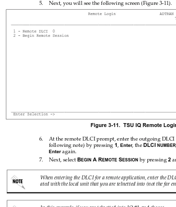
5. Next, you will see the following screen (Figure 3-11).
Figure 3-11. TSU IQ Remote Login Screen
6. At the remote DLCI prompt, enter the outgoing DLCI (see following note) by pressing 1, Enter, the DLCI NUMBER, and
Enter again.
7. Next, select BEGIN A REMOTE SESSION by pressing 2 and Enter.
Remote Login ADTRAN TSUIQ Telnet _______________________________________________________________________________
1 - Remote DLCI 0 2 - Begin Remote Session
_______________________________________________________________________________ Enter Selection ->
When entering the DLCI for a remote application, enter the DLCI associ-ated with the local unit that you are telnetted into (not the far end DLCI).
In this example, if you are telnetted into IQ #1 and choose
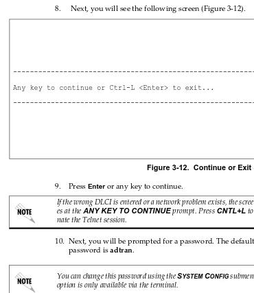
8. Next, you will see the following screen (Figure 3-12).
Figure 3-12. Continue or Exit Screen
9. Press Enter or any key to continue.
10. Next, you will be prompted for a password. The default password is adtran.
---Any key to continue or Ctrl-L <Enter> to exit...
---If the wrong DLCI is entered or a network problem exists, the screen
freez-es at the ANY KEY TO CONTINUE prompt. Press CNTL+L to
termi-nate the Telnet session.
You can change this password using the SYSTEM CONFIG submenu. This
11. You will now see the MAIN MENU of the remote unit.
See Figure 3-13.
Figure 3-13. TSU IQ Remote Main Menu Screen
12. Notice when you are telnetted into the remote unit, the word
Remote appears in the upper right-and corner.
Main Menu ADTRAN TSUIQ Remote _______________________________________________________________________________
1 - Configuration 2 - View Statistics 3 - Test
4 - Logout
TSU IQ MENU STRUCTURE
The opening menu is the access point to all other operations. The main menu branches are CONFIGURATION, VIEW STATISTICS, TEST,
DIAL, and LOGOUT. See Figure 3-4 on page 3-6. Each main menu item has several functions and submenus to identify and access specific parameters.
Main Menu
Definitions for the branches of the main menu follow:
Configuration (CONFIG)
CONFIGURATION is used to select DTE Port, Network Port, DBU,
Control and system operating parameters. For more information on configuration options, see the following chapters: Configuration
Overview on page 5-1, DTE Port Configuration on page 6-1, Network
Port Configuration on page 7-1, Configuring DBU Options on page 8-1,
and System Configuration on page 9-1.
View Statistics (STATS)
This selection displays statistical information for the DTE port, network port, dial backup port, and the system. See Statistics on
page 10-1 for more information.
Test
TEST options allow you to perform PVC loopback tests. See Testing
on page 11-1 for more information.
Dial
This selection allows you to access manual dialing capabilities. See
Activating Dialing Functions on page 12-1 for more information.
Logout (terminal menu only)
This parameter logs out of the system.
The LOGOUT selection is available on the terminal interface only.
This chapter provides examples of some common TSU IQ management options as well as an example of a dial backup application. The management application examples include VT-100 management, out-of-band SNMP/Telnet management, and in-band PVC SNMP/Telnet management. Descriptions and
configuration tips for these options are provided in the sections that follow.
MANAGEMENT APPLICATIONS
One of the main advantages of the TSU IQ is management flexibility. The TSU IQ front panel interface provides complete configuration capabilities and viewing of key frame relay statistics information. Other management options described in this chapter provide configuration and diagnostics capabilities as well as all-inclusive statistics information.
Local VT-100 Terminal Management
Connect a VT-100 terminal to the TSU IQ CONTROLport. This interface provides full-screen configuration and all-inclusive statistics access. VT-100 management also allows for remote configuration. Through this port, a remotely located TSU IQ is fully accessible for configuration, diagnostics, and statistics viewing. Figure 4-1 shows an example of a VT-100 application.
Figure 4-1. VT-100 Management Application Example
Minimum Configuration Requirements for VT-100 Management
The following options are the minimum configuration requirements for establishing VT-100 management access.
Baud Rate
Set the baud rate to match the VT-100 terminal rate. This is accessible from the front panel only (select CONTROL PORT from the
CONFIGURATION menu).
Control Port Mode
Set the CONTROL PORT MODE for TERMINAL. This selection is found in the SYSTEM portion of the CONFIGURATION menu.
VT-100 remote mode is proprietary and non-intrusive. Therefore, you can perform all VT-100 management functions without disrupting the flow of data.
VT -100 Router Router TSU IQ
Frame
Relay
DSU IQRD1 TD2RD2 TDNRDN TD1 ALM /TST 1 A C B 4 D F E SHIFTDELETE QUICK
NEXT7 PREVADD
2 5 # 3 6 9 8 0 TSU IQ DSU IQ
RD1 TD2RD2 TDNRDN TD1 ALM /TST 1 A C B 4 D F E SHIFTDELETE QUICK
NEXT7 PREVADD
Out-of-Band Management
This management option (shown in Figure 4-2) is commonly used in situations where the customer is trying to reduce the amount of management traffic flowing through the frame relay device. The TSU IQ can be managed though an established Telnet session or an SNMP-based network manager like HP OpenView®, IBM
Netview®, or SunNet Manager®.
SNMP and Telnet management is provided by one of the following interfaces:
• A device (e.g., a router) running SLIP protocol. Connection is made through the TSU IQ's Control port.
• A device (e.g., a router) running async PPP protocol. Connection is made through the TSU IQ's control port. • A LAN. Connection is made through the optional 10BaseT
ethernet interface provided on the ethernet card (P/N 1204005L1).
The ADTRAN TSU IQ MIB is available in the support section of the ADTRAN Web page at www.adtran.com.
Router 10BaseT Ethernet SLIP/PPP Router TSU IQ NMS
Frame
Relay
DSU IQRD1 TD2RD2 TDNRDN TD1 ALM/TST 1A C B 4 D F E SHIFTDELETE QUICK NEXTPREV ADD 7 2 5 # 3 6 9 8 0 TSU IQ DSU IQ
Configuration System Menu>Minimum Configuration Requirements
The following options (all found in the SYSTEM portion of the
CONFIGURATION menu) are the minimum configuration
requirements for establishing out-of-band SNMP or Telnet access. Once these options are configured, the unit may be accessed using SNMP/Telnet.
IP Address
Enter the TSU IQ IP address.
Control Port Mode
If necessary, select SLIP or PPP as the TSU IQ control port mode. If the ethernet card is the interface type, this parameter does not affect setup.
Subnet Mask
Enter the subnet mask number assigned to the network formed by the TSU and the other FRAD/routers across the frame relay network. This address is available from the network administrator and is only necessary when using the ethernet card.
Gateway IP Address (if required)
Enter the Gateway node IP address. This address is applicable only if the TSU IQ and the network manager are connected through a Gateway node. This address is available from the network administrator and is only necessary when using the ethernet card.
The next five settings are applicable for SNMP access only.
Read Community Name
Set the READ COMMUNITY NAME to match the NMS (network management system) settings.
Write Community Name
Set the WRITE COMMUNITY NAME to match the NMS settings.
Trap Manager DLCI
Trap Manager IP Address
Enter the IP address of the SNMP manager to which the TSU IQ sends traps. This selection is found under
CONFIGURATION>SYSTEM>TRAP MGR OPTIONS.
Trap Manager Port
Enter the TSU IQ port used to transmit traps to the SNMP manager. This selection is found under CONFIGURATION>SYSTEM>TRAP MGR OPTIONS.
In-Band Management
The ADTRAN TSU IQ supports three modes of in-band management using the frame relay structure of PVCs. These modes are local, shared, and dedicated PVC management. All three types support complete SNMP management as well as Telnet capabilities.
Local PVC Management
Local PVC management refers to a PVC created between the TSU IQ and the frame relay router on the DTE interface of the TSU IQ (see Figure 4-3 on page 4-6). This type of management is ideal when local management is needed but an ethernet connection is not available. To support this type of management, all traffic on the selected PVC must be RFC 1490 encapsulated, noncompressed IP traffic.
The local PVC is sent out of the WAN serial port of the router as normal WAN traffic and is terminated in the TSU IQ. Since the TSU IQ responds to Inverse ARP, it is not necessary to set up a static route in the router. The router will discover the IP address
automatically; however, it will be necessary to set up a local PVC between the router and the TSU IQ. Accomplish this by setting a value (between 16 and 1007) for the DTE management DLCI on the
Local PVC management can be used at any location that has a router. Therefore, remote sites can be accessed through the remote router. One consideration when using local PVC management is that if the remote router goes down, access to the remote TSU is lost.
Figure 4-3. Local PVC Management Application
Minimum Configuration Requirements for Local PVC Management
The following options are the minimum configuration
requirements for establishing in-band local PVC management. Once these options are configured, the unit may be accessed using SNMP/Telnet. All options (with the exception of the MANAGEMENT DLCI option) are found in the SYSTEM portion of the
CONFIGURATION menu.
IP Address
Enter the TSU IQ IP address.
Management DLCI
Enter a DLCI number (between 16 and 1007) that is not used by the frame relay service. This option is found in the FRAME RELAY OPTIONS portion of the DTE PORT CONFIGURATION menu.
The next five settings are applicable for SNMP access only.
NMS Router Router TSU IQ
Frame
Relay
DSU IQRD1 TD2RD2 TDNRDN TD1 ALM /TST 1 A C B 4 D F E SHIFT DELETEQUICK NEXT PREVADD 7 2 5 # 3 6 9 8 0 TSU IQ DSU IQ
Read Community Name
Set the READ COMMUNITY NAME to match the NMS settings.
Write Community Name
Set the WRITE COMMUNITY NAME to match the NMS settings.
Trap Manager DLCI
Identify the virtual circuit used for all traps generated by the TSU IQ. This selection is found under CONFIGURATION>SYSTEM>TRAP MGR OPTIONS.
Trap Manager IP Address
Enter the IP address of the SNMP manager to which the TSU IQ sends traps. This selection is found under CONFIGURATION> SYSTEM>TRAP MGR OPTIONS.
Trap Manager Port
Enter the TSU IQ port used to transmit traps to the SNMP manager. This selection is found under CONFIGURATION>SYSTEM>TRAP MGR OPTIONS.
Shared PVC Management
Shared PVC management refers to a PVC that is used for normal data traffic between locations (see Figure 4-4 on page 4-8). The TSU IQ monitors this PVC for packets that contain its IP address. When the TSU IQ detects a packet containing a destination IP address that matches the TSU IQ IP address, the unit intercepts the packet and processes its TCP/IP information. To support this type of
management, all traffic on the selected PVC must be RFC 1490 encapsulated, noncompressed IP traffic.
Shared PVC management is used to manage remote TSU IQs without being dependent on services from the remote router. This usually requires a static route at the host location.
Figure 4-4. Shared PVC Management Application
Minimum Config Requirements for Shared PVC Management
The following options are the minimum configuration
requirements for establishing in-band shared PVC management. Once these options are configured, the unit may be accessed using SNMP/Telnet. All options (with the exception of the MANAGEMENT DLCI options) are found in the SYSTEM portion of the
CONFIGURATION menu.
IP Address
Enter the TSU IQ IP address.
Management DLCI 1 and/or DLCI 2
Enter the management DLCI(s) used to carry management traffic to and from the network. This option is found in the NETWORK PORT CONFIGURATION menu.
Management DLCI 1 and/or DLCI 2 Mode
Set to DEDICATED if the management DLCI is used only to manage the TSU IQ (and not used to carry customer traffic). If set to
DEDICATED, the router is not notified of that DLCI. Set to SHARED if the DLCI is used to carry customer traffic as well as management data. This option is found in the NETWORK PORT CONFIGURATION
menu.
NMS
Router Router
TSU IQ TSU IQ
Frame
Relay
DSU IQ RD1 TD2 RD2 TDNRDN TD1 ALM/TST 1 A C B 4D F E SHIFTDELETE QUICK NEXT PREVADD 7 2 5 # 3 6 9 8 0 DSU IQ RD1 TD2 RD2 TDNRDN TD1 ALM/TST 1 A C B 4D F E SHIFTDELETE QUICK NEXT PREVADD 7 2 5 # 3 6 9 8 0LAN
LAN
The next five settings are applicable for SNMP access only.
Read Community Name
Set the READ COMMUNITY NAME to match the NMS settings.
Write Community Name
Set the WRITE COMMUNITY NAME to match the NMS settings.
Trap Manager DLCI
Identify the virtual circuit used for all traps generated by the TSU IQ. This selection is found under CONFIGURATION>SYSTEM>TRAP MGR OPTIONS.
Trap Manager IP Address
Enter the IP address of the SNMP manager to which the TSU IQ sends traps. This selection is found under CONFIGURATION> SYSTEM>TRAP MGR OPTIONS.
Trap Manager Port
Enter the TSU IQ port used to transmit traps to the SNMP manager. This selection is found under CONFIGURATION>SYSTEM>TRAP MGR OPTIONS.
Dedicated PVC Management
Dedicated PVC management refers to the ability to have a PVC originated from the network and terminated in the TSU IQ (see Figure 4-5 on page 4-10). This is an ideal configuration for third-party management. It isolates the customer’s data traffic from network management traffic, and it also acts as a fire-wall that restricts management data to the TSU. Dedicated PVC
Figure 4-5. Dedicated PVC Management Application
Configuration Requirements for Dedicated PVC Management
The minimum configuration requirements for dedicated PVC management are identical to those listed for shared PVC
management. See the previous section, Shared PVC Management on
page 4-7, for more information.
DIAL BACKUP APPLICATION
The TSU IQ dial backup (DBU) option cards provide single or multiple site backup, depending on the DBU card option selected. The TSU IQ can be configured to originate a call based on physical layer conditions (i.e., port failures) and/or PVC outages. Once the criteria are met, the TSU IQ establishes a call to the configured phone number (see Table 4-1 on page 4-13) and the connection is used to carry traffic for the PVC(s) configured for DBU operation.
In the case of PVC outages (not physical layer port failure), the TSU IQ's two-port design allows the TSU IQ receiving the call to continue to use the T1 frame relay circuit for PVCs that are not affected by the outage. This is done (without the attached DTE device's intervention) by modifying the status of PVCs that are in DBU state to active when the PVC status is given to the DTE.
A TSU IQ with multiple PVCs to multiple sites can also originate a call to one site during an outage and restore connection for PVCs to that destination. With all DBU cards except for the PRI card, you can make only one call at a time. The other PVCs to other sites in
Carrier NMS
Router Router
TSU IQ TSU IQ
Frame
Relay
DSU IQ
RD1 TD2RD2 TDNRDN TD1 ALM/TST 1A C B 4 D F E
SHIFTDELETEQUICK
NEXT7PREVADD
2 5 # 3 6 9 8 0 DSU IQ
RD1 TD2RD2 TDNRDN TD1 ALM/TST 1A C B 4 D F E
SHIFTDELETEQUICK
NEXT7PREVADD
this scenario will be inactive. If you have a PRI card you can originate or answer up to 23 calls.
Information entered into the PVC CONFIGURATIONtable (see Table 4-2 on page 4-13) marks PVCs for DBU operation. The key element in each entry of the table is the DBU DLCI. For each PVC
connecting two sites for DBU operation, the DLCI field represents the PVC DLCI at the local UNI and the DBU DLCI represents the PVC DLCI at the remote site UNI. The TSU IQ uses this
information in the outbound side to change the PVC DLCI so the far end DTE device receives frames on the DBU PVC addressed in the same manner as when the frame relay circuit is operational. For PVCs not used for DBU operation, leave the DBU PHONE NUMBER
field set for a null entry. Enter a space character from the VT-100 terminal to create a null entry for DBU PHONE NUMBER field.
The DBU PHONE NUMBER is only required for the TSU IQ originating the call.
.
DBU Application 1 (non-PRI)
The following application shows the critical configuration required for a case where all end points of the frame circuit are equipped with single call DBU units (see Figure 4-6). This set-up allows any remote site to place a call to the host site or the host site to place a call to each remote site based on PVC failure. This set-up also allows the host to designate primary and alternate sites to call based on port failure criteria using the call order parameter.
Figure 4-6. Dial Backup Application (non PRI)
Table 4-1. Example Settings for Dial Backup Options
Table 4-2. Example Settings for PVC Configuration Table
Option Settings
Auto DBU Enable
DBU Criteria With Network Fail: Enable With No LMI: Enable With PVC Inactive: Enable
SITE A (ENTRY #1)
SITE A (ENTRY #2)
SITE B SITE C
DLCI 16 17 116 117
DBU DLCI* 116 117 16 17
DBU Phone #** Site B # Site C # Site A # Site A #
DBU Call Order 1 2 None None
DBU on Inactive*** Enabled Enabled Enabled Enabled
* DBU DLCIs and DBU phone number must be entered to provide dial backup for a DLCI.
** DBU phone number - All DLCIs to the same site should have the same phone number
DBU Application 2 - PRI
The following application shows the critical configuration for a case where the Host Site of the frame relay circuit is set up to restore service (see Figure 4-7). This setup uses a PRI ISDN module and service so that multiple calls can be placed simultaneously. The criteria for placing a call are based on Host Site port failure or individual PVC failure. The individual PVC failure should account for remote sites port outages and frame relay service troubles.
Figure 4-7. PRI DBU Card at Host Site (A)
Table 4-3, Table 4-4, and Table 4-5 on page 4-15 show example setups for PRI DBU options at the Host Site. These tables are based on the example application shown in Figure 4-7.
Table 4-3. Example Settings for PRI DBU Card (A)
Table 4-4. Global DBU Settings (B and C)
Table 4-5. Example Settings for PRI DBU Card at Host Site Auto DBU Enabled
DBU Criteria With Net Fail: Enabled With No LMI: Enabled With PVC inactive: Enabled
Auto DBU Enabled
DBU Criteria With Net Fail: Disabled With No LMI: Disabled With PVC inactive: Disabled
SITE A SITE A SITE A
(ENTRY #1)
DLCI 16 17 19
DBU DLCI* 100 101 200
DBU PHONE #** Site B# Site B# Site C#
DBU on Inactive*** Enabled Enabled Enabled
* DBU DLCIs and DBU phone number must be entered to provide dial backup for a DLCI.
** DBU phone number - All DLCIs to the same site should have the same phone number
LOCAL AND REMOTE CONFIGURATION
The TSU IQ can be configured locally or communications can be established so that a local TSU IQ can configure a remote TSU IQ using a VT-100 interface. See Operation on page 3-1 for information on selecting LOCAL or REMOTEoperation.
The CONFIGURATION menu consists of submenus relating to specific
interfaces or functions of the TSU IQ requiring setup:
• DTE Port • Network Port
• Dial Backup (if DBU card is installed) • Control Port (front panel only) • System
The terminal CONFIGURATION menu is shown in Figure 5-1 on page 5-2.
For detailed information on configuration, see the chapters DTE Port Configuration on page 6-1, Network Port Configuration on page 7-1,
Configuring DBU Options on page 8-1, and System Configuration on
CONFIGURATION menu trees are shown in Figure 5-2 on page 5-3 (for
the terminal interface) and Figure 5-3 on page 5-4 (for the front panel interface).
1 None 1 Flow Control 2 Hardware 1 Physical Layer Options 3 FECN/BECN 1 DTE Port
2 Frame Relay Options 1 T392 1 Forced On 2 N392 2 CTS Option 2 Follow RTS 3 N393
4 MGT DLCI 1 Enabled 1 Always On 3 DSR Option 1 Forced On 5 MGT PVC Opt 2 Disabled 2 Follow Network 4 CD Option 2 Normal 6 Sig Responses 3 Always Off
1 Normal 5 TC Clock Option 2 Inverted
1 Config 1 D4
1 Framing 2 EDF
1 Physical Layer Opts 3 Auto
2 Line Code 1 B8ZS 2 Network Port 2 Frame Relay Options 1 Signal Type 1 None 2 AMI
3 MGT DLCI 1 2 T391 2 LMI
4 MGT DLCI 2 3 N391 3 ANSI T1.617-D 1 Internal 5 MGT DLCI 1 Mode 1Shared 4 N392 4 ITU-T Q.933-A 3 Clock Source 2 From Network 6 MGT DLCI 2 Mode 2 Dedicated 5 N393 5 Auto 3 Base DTE
7 PVC Count 4 Base DSX-1
8 Hist. Interval Count 1 DLCI
9 PVC Options 2 DBU DLCI** 1 Auto
3 DBU Phone # 4 Line Build Out 2 0 3 DBU** See Chapter 8 for this part of the menu tree 4 DBU on Inactive 3 7.5
5 DBU Call Order # 4 15.0
6 CIR (Kbps) 5 22.5
7 Seq Number 1 Disabled
8 PVC Delay 2 Enabled 1 Auto 5 RX Sensitivity 1 Normal 9 Stats Option 2 Enabled 2 Extended 10 Next 3 Disabled
11 Prev 1 Change Password 12 Add 2 IP Address 13 Delete
3 Subnet Mask* 1 Terminal 6 Channel Bandwidth 1 X56K 4 IP Address* 2 Slip Protocol 2 X64K 5 Control Port Options 1 Control Port Mode 3 PPP Protocol
4 System 6 Read Community 7 Write Community
8 Trap MGR Options 1 Trap Mgr DLCI 7 Channel Alignment 1 Contiguous 2 Trap Mgr IP 1 None 2 Alternating 9 Protocol 1 1 None 3 Trap MGR Port 2 DTE Port 8 Start Channel
10 Protocol 2 2 IP 4 Next 3 Network Port 9 Number of Channels 11 System Time 3 IPX 5 Previous 4 Control Port 10 Transmit PRM 1 Yes 12 System Date 1 5 Min 4 ARP 6 Add 2 No
2 10 Min 5 SNA 7 Delete 13 History Interval Size 3 15 Min 6 Unknown
Figure 5-3. Front Panel Configuration Menu Tree 1 None 1 Flow Control 2 Hardware
3 FECN/BECN 1) Physical Layer Options
1 Forced On 1 DTE Port 1 T392 2 CTS Option 2 Follow RTS
2 Frame Relay Options 2 N392
3 N393 3 DSR Option 1 Forced On 4 MGT DLCI 1 Enabled 1 Always On 4 CD Option 2 Normal 5 MGT PVC Opt 2 Disabled 2 Follow Network
6 Signaling Resp 3 Always Off 1 Normal 5 TC Clock Option 2 Inverted
3 External
1 D4
1 Config 1 Framing 2 EDF
1 Physical Layer Opts 3 Auto
2 Network Port
2 Frame Relay Options 1 Signal Type 1 None 2 Line Code 1 B8ZS
2 T391 2 LMI 2 AMI
3 DLCI 1 3 N391 3 ANSI
4 DLCI 2 4 N392 4 ITU-T 1 Internal 5 DLCI 1 Mode 1 Shared 5 N393 5 Auto 3 Clock Source 2 From Network 6 DLCI 2 Mode 2 Dedicated 3 Base DTE
7 PVC Count 1 DLCI 4 Base DSX-1
8 Hist. Interval Count 2 DBU DLCI
9 PVC Config 3 DBU Phone # 1 Auto 3 DBU** See Chapter 8 for this part of the menu tree 4 DBU On Inactive 4 Line Build Out 2 0
5 DBU Call Order # 3 7.5
96000 6 CIR (kbps) 4 15.0
4 Control 1 Baud Rate 19.2 7 Seq Num 1 Disabled 1 Auto 5 22.5 38.4K 8 PVC Delay 2 Enabled 2 Enabled
9 Stats Option 3 Disabled 5 RX Gain 1 Normal
10 Next 2 Extended
11 Prev 12 Add 13 Delete
1 IP Address
2 Subnet Mask* 1 Terminal
3 IP Address* 2 SLIP Protocol 6 Channel Rate 1 56K 5 System 4 Control Port Options 1 Control Port Mode 3 PPP Protocol 2 64K
5 Read Community
6 Write Community 7 Transmit PRM 1 Yes 7 Trap MGR Options 1 Trap DLCI 2 No
2 Trap IP
8 Protocol 1 1 None 3 Trap Port 1 None 9 Protocol 2 2 IP 2 DTE Port A System Time 3 IPX 1 5 Min 3 Network Port B System Date 4 ARP 2 10 Min 4 Control Port
5 SNA 3 15 Min 5 Ethernet Port* 6 Unknown 4 20 Min
Configure the physical layer and frame relay protocol options for the DTE port located on the rear of the TSU IQ by selecting DTE PORT from the CONFIGURATION menu. Figure 6-1 shows the
terminal CONFIGURATION menu for the DTE Port. Figure 6-2 on
page 6-2 shows the menu tree for this section. The menu descriptions follow the menu tree.
Figure 6-1. Terminal DTE Port Configuration Menu
Figure 6-2. DTE Port Menu Tree
Physical Layer Options (PHYS LYR OPT)
Flow Control
This option determines how the TSU IQ responds to congestion during DBU operation.
None
No flow control is used and the TS