ABSTRACT
Keene, Brandi Nechelle. Biodegradation of Polypropylene Nonwovens. (Under the direction of Dr. Richard Kotek).
The primary aim of the current research is to document the biodegradation of
polypropylene nonwovens and filament under composting environments. To accelerate the
biodegradation, pre-treatments and additives were incorporated into polypropylene
filaments and nonwovens.
The initial phase (Chapter 2) of the project studied the biodegradation of untreated
polypropylene with/without pro-oxidants in two types of composting systems. Normal
composting, which involved incubation of samples in food waste, had little effect on the
mechanical properties of additive-free spunbond nonwovens in to comparison
pro-oxidant containing spunbond nonwovens which were affected significantly. Modified
composting which includes the burial of samples with food and compressed air, the
polypropylene spunbond nonwovens with/without pro-oxidants displayed an extreme
loss in mechanical properties and cracking on the surface cracking.
Because the untreated spunbond nonwovens did not completely decompose, the next
phase of the project examined the pre-treatment of γ-irradiation or thermal aging prior to
composting. After exposure to γ- irradiation and thermal aging, polypropylene is subjected
to oxidative degradation in the presence of air and during storage after irradiation. Similar to
photo-oxidation, the mechanism of gamma radiation and thermal oxidative degradation is
fundamentally free radical in nature.
polypropylene nonwovens with/without additives. Cracking on both the pro-oxidant and
control spunbond nonwovens was showed by SEM imaging.
Spunbond polypropylene nonwovens with/without pro-oxidants were also pre-
irradiated by gamma rays followed by composting. Nonwovens with/without pro -oxidants
were severely degraded by γ-irradiation after up to 20 kGy exposure as explained in Chapter
4. Furthermore (Chapter 5), γ-irradiated polypropylene nonwovens with pro-oxidants were
invisible to the naked eye after 30 days of composting suggesting microbial attack was
achieved.
The final phase of the project enco mpasses the extrusion of bicomponent fibers.
Because microorganisms desire to feed on hydrophilic molecules, commercially available
starch -based polymers were spun with polypropylene resins in a sheath/core configuration.
Similar to the previously discussed nonwovens studies, the bicomponent filaments were pre-
treated with heat (Chapter 6) and γ-rays (Chapter 7) before evaluating the biodegradability
under composting studies. The results from these chapters were reviewed to determine if
© Copyright 2012 by Your Name
Biodegradation of Polypropylene Nonwovens
by
Brandi Nechelle Keene
A dissertation or thesis submitted to the Graduate Faculty of North Carolina State University
in partial fulfillment of the requirements for the degree of
Doctor of Philosophy
Fiber and Polymer Science
Raleigh, North Carolina
2012
APPROVED BY:
_______________________________ ______________________________
Dr. Richard Kotek Dr. Mohamed Bourham
Committee Chair
________________________________ ________________________________
DEDICATION This work is dedicated to:
My Lord and Savior, Jesus Christ. For I know that through you, all things are
possible.
To my husband Travis, for being my biggest fan even when I may have not deserved
it. I love you!!!
My phenomenal parents and baby sister for being brilliant examples of love, prayer,
faith, hope, and perseverance.
Lastly, my extended family and friends for understanding when I was unable to attend a
BIOGRAPHY
Brandi Nechelle Keene was born and raised in Ahoskie, NC. At a very early age Brandi
developed a passion for science and math. This passion continued to grow as a result of
Brandi completing advance placement chemistry while attending Hertford County High
School. As a result, Brandi pursued a Bachelor of Science degree in chemistry at North
Carolina State University and a Master of Science degree in chemistry at North Carolina
Central University. Following graduate school, Brandi will be employed by the United
States Department of Defense as a research chemist. In addition, she plans to volunteer in
ACKNOWLEDGMENTS
First and foremost, I would like to thank my Heavenly Father for giving me the strength, ability, and motivation to fulfill the requirements to complete this dissertation. For I know with him, all things are possible.
Next, I would extend my gratitude to my committee members, Dr. Mohamed Bourham, Dr. Peter Hauser, Dr. Ahmed El-Shafei, Dr. Saundra Delauder, and my advisor, Dr. Richard Kotek. Each of you has played a major role on my success to complete this thesis beyond being a member on my committee. Particularly, I would like to thank Dr. Kotek for his guidance,
continuous encouragement, insight, and support throughout my graduate career. Your dedication to your research group is indescribable.
In addition to my committee members, I also owe a huge “thank you” to various lab
managers, technicians, and departmental administrators. Whether it was helping me to order supplies or conduct analysis, your support is appreciated. In particular, I would like to send a special thanks to Birgit Anderson, Judy Elison, Theresa White, Dr. Jan Ballard, Jeff White, Tri Vu, Mr. Nuygen, Dr. William Oxenham, Dr. Jon Rust, and Traci Figura. I would also like to acknowledge the Graduate School staff, Dr. Duane Larick, Dr. David Shafer, Alison Al- baati, and Dr. Mike Carter for your continuous support and encouragement.
I am also grateful to my past and current research group members. Your continuous input and support is beyond immeasurable.
TABLE OF CONTENTS
LIST OF TABLES ... viii
LIST OF FIGURES ... ix
CHAPTER 1 Literature Review ...1
1.1 BACKGROUND ...1
1.2 Overview of Polypropylene ...1
1.3 Manufacture of Polypropylene Fibers ...7
1.4 Degradation Mechanisms of Polypropylene ... 28
1.5 Thermal Degradation ... 46
1.6 γ-Irradiation ... 51
1.7 Biodegradation of Polypropylene ... 57
1.8 Composting ... 83
1.9 Conclusion ... 97
CHAPTER 2 Characterization of the Compostability of Untreated Spunbond Polypropylene and Pro-oxidant Additive Containing Nonwovens ... 102
2.1 Introduction ... 102
2.2 Experimental ... 106
2.3 Results and Discussion ... 110
2.4 Conclusion ... 133
CHAPTER 3 Biodegradation of Untreated and Thermally Pre-treated Spunbond Polypropylene Nonwovens in Composting Environments ... 135
3.1 Introduction ... 135
3.2 Materials and Methods ... 137
3.3 Results and Discussion ... 142
3.4 Conclusion ... 171
CHAPTER 4 Characterization of Degradation of Polypropylene Nonwovens ... 172
Irradiated by γ-Ray ... 172
2. Experimental ... 176
3. Results and Discussion ... 179
4. Conclusion ... 197
CHAPTER 5 Compostability of γ-Irradiated Spunbond Polypropylene With/Without Pro-oxidant Additive Containing Nonwovens ... 199
5.1 Introduction ... 199
5.2 Materials and Methods ... 201
5.3 Results and Discussion ... 206
5.3.1 Temperature Profile During Composting ... 206
5.3.2 Effect of γ-Irradiation on Nonwovens ... 208
5.3.3 Normal Composting of γ-Irradiated Spunbond Nonwovens... 210
5.3.4 Modified Composting of γ-Irradiated Nonwovens ... 216
5.3.5 Normal and Modified Composting of γ-Irradiated Spunbond Nonwovens with TDPATM Pro-oxidants ... 227
5.4 Conclusion ... 230
CHAPTER 6 Compostability of Polypropylene and Starch-based Bicomponent Filaments after Thermal Aging ... 231
6.1 Introduction ... 231
6.2 Materials and Methods ... 234
6.3 Results and Discussion ... 239
6.3.1 Temperature Profile During Composting ... 239
6.3.2 Effect of Thermal Aging on Polypropylene with/without Starch-based Additives ... 241
6.3.3 Normal Composting of Thermal Aging on Polypropylene with/without Starch-based Additives ... 248
6.3.4 Modified Composting of Thermal Aging on Polypropylene Filaments with/without Starch-based Additives ... 255
CHAPTER 7 Compostability of Polypropylene and Starch-based Bicomponent Filaments
after γ-Irradiation ... 267
7.1 Introduction ... 267
7.2 Materials and Methods ... 275
7.3. Results and Discussion ... 277
7.3.1Temperature Profiling During Composting ... 282
7.3.2 Effect of γ-Irradiation on Polypropylene with/without Starch-based Additives ... 282
7.3.3 Normal Composting of γ-Irradiated Polypropylene with/without Starch-based Additives ... 289
7.3.4.Modified Composting of γ-Irradiated Polypropylene with/without Starch-based Additives ... 289
7.4 Conclusion ... 297
CHAPTER 8 Conclusions ... 299
8.1 Introduction ... 299
8.2 Abiotic Degradation Summary ... 299
8.3 Biotic Degradation Summary... 301
8.4 Conclusions and Recommendations ... 303
REFERENCES... 308
LIST OF TABLES
Table 1 Properties of Textile Grade Polypropylene ...6
Table 2 Properties of Polypropylene Films After Outdoor Weathering in Nigeria ... 37
Table 4 Crystallinity of cooled (FC) and quenched (FQ) polypropylene films... 50
Table 4 Common gamma emitters ... 52
Table 5 List of Published Literature Documenting Biodegradation of Polypropylene/Blends ... 63
Table 6 (continued)List of Published Literature Documenting Biodegradation of ... Polypropylene/Blends... 64
Table 7 Mean Breaking Strength of Various Polypropylene Nonwovens111 ... 64
Table 8 Visual Growth of A.niger on Various Polymer Films86 ... 65
Table 9 Visual Growth Test Results of Polymers As a Function of γ-sterilization83 ... 67
Table 10 Breaking Strength Loss and Fungal Growth Rate (shown in parenthesis).94 ... 73
Table 11 Desired Characteristic for Effective Composting116 ... 90
Table 12 Summary of Previously Discussed Polypropylene Degradation Technologies ... 100
Table 2.1 Melt Spinning Parameters of Spunbond Polypropylene Nonwovens ... 107
Table 3.1 Melt Spinning Parameters of Spunbond Polypropylene Nonwovens ... 138
Table 5.1 Melt Spinning Parameters of Spunbond Polypropylene Nonwovens ... 202
Table 2: Process Parameter of Bicomponent Filaments ... 271
Table 1 Effect of Gamma Irradiation on Elongation at Break (mm) and peak load (lbf) of Spunbond and Meltblown Polypropylene Nonwovens. ... 315
Table 2 Effect of γ-irradiation dose on thermal properties of spunbond polypropylene... 315
Table 3 Effect of γ-irradiation dose on thermal properties of meltblown polypropylene. .... 315
Table 4 Peak position, d-spacing, and half-widths of (110), (040), and (130) reflections of spunbond polypropylene nonwovens. ... 316
LIST OF FIGURES
Figure 1 Synthesis of Polypropylene...2
Figure 2 Tacticities of Polypropylene ...3
Figure 3 Schematic of Melt Spinning ...8
Figure 4 Expected Growth of Nonwovens in Specific Applications ... 11
Figure 5 Melt Blown Process Technology ... 13
Figure 6 Schematic of Fiber Attenuation in the Meltblowing Process ... 15
Figure 7 Spunbond Process ... 19
Figure 8 Material Breakdown of Waste Generated by Americans in 2009... 22
Figure 9 Amount of Nonwovens Produced Globally ... 23
Figure 10 Percentage of Nonwovens Produced Globally ... 24
Figure 11 Polymers Used in Nonwovens Since 1981 ... 25
Figure 12 Lifetime of Nonwovens ... 26
Figure 13 Various Polymer Degradation Routes ... 29
Figure 14 Electromagnetic Spectrum ... 30
Figure 15 Decomposition of Carbonyl Compounds through Norrish I Reaction ... 32
Figure 16 Formation of Carbonyl Groups During Photo-oxidative Degradation of Polypropylene ... 33
Figure 17 Decomposition of Carbonyl Groups through Norrish II Reactions ... 34
Figure 18 Schematic of degradation mechanism of polypropylene plates ... 38
Figure 19 (Left) Residual Strength of Polypropylene Filaments after One Year Exposure and (Right) Correlation between Residual Strength and Intrinsic Viscosity ... 39
Figure 20 (Left) Molar Mass (g mol-1) of Polypropylene films after 48 day exposure with (A) 0 mg kg-1 (B) 100 mg kg-1 (C) 300 mg kg-1of anti-oxidant and (D) control. (Right) Crystallinity of polypropylene with no antioxidant up to 300 days ... 40
Figure 21 The carbonyl (left) and hydroxyl (right) band intensity of the polypropylene fabric exposed to UV radiation at 254 nm for different times ... 42
Figure 22 Cross-section of stained polypropylene fiber after 50, 115, and 165 hr of accelerated weathering testing ... 43
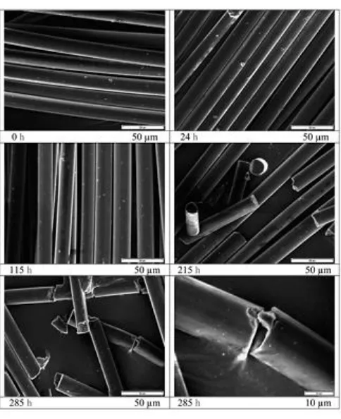
Figure 23 SEM of polypropylene fibers after 285 hours of accelerated weathering test ... 44
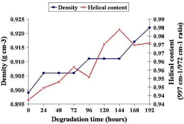
Figure 24 Changes of density and helical content of polypropylene nonwovens at various degradation times ... 45
Figure 25 Degree of crystallinity as a function of molar mass to determine embrittlement behavior ... 49
Figure 26 Melt flow rate of recycled polypropylene (red) and virgin polypropylene (blue) films ... 51
Figure 27 Comparison of penetration distances of alpha, beta, and gamma rays ... 53
Figure 28 Oxidation of polypropylene during γ-radiation... 54
Figure 30 Influence of γ-irradiation on the viscosity-average molecular weight, viscosity,
elongation at break, and toughness of polypropylene films(left) and yarns(right) ... 56
Figure 31 SEM of γ-sterilized polypropylene films at (left) 780 Gy/hr and 600 Gy/hr... 57
Figure 32 Biodegradation Mechanism of Polymers ... 58
Figure 33 Schemes of Aerobic and Anaerobic Biodegradation... 59
Figure 33 Weight losses of polypropylene and polyethylene after composting ... 62
Figure 34 BacLight staining image of thermal pretreated polypropylene after 12 months of soil burial ... 65
Figure 35 Phases of Biodegradation in Polymer Blends ... 68
Figure 36 TGA and DTG curves at 10˚C min-1 for polypropylene, starch, and blend prior to soil burial (left) and blend after 12 months of soil burial (right) ... 69
Figure 37 Biodegradation curves for polypropylene composites containing natural fibers 70
Figure 38 SEM micrograph of partially degraded polypropylene composites of pineapple leaves (top, left), banana (top, right) and bamboo (bottom, center) ... 71
Figure 39 Scheme of photodegradation and biodegradation of polypropylene with and without pro-oxidant additive ... 76
Figure 40 SEM images of the tested pro-oxidant containing materials after approximately 100 days of incubation (a) Oxidized HDPE abiotic; (b) oxidized HDPE R. rhodochrous; (c) oxidized LDPE M. alpina; (d) oxidized LDPE N. asteroides; (e) oxidized LDPE R. rhodochrous; (f) oxidized LDPE abiotic. ... 78
Figure 41 Pictures of the PP and PPOx samples after 56 days in soil compost ... 79
Figure 42 Carbon mineralization of low density polyethylene films (a and b) referenced to cellulose in soil burial ... 81
Figure 43 Mineralization profiles of thermally fragmented low density polyethylene containing TDPATM (Q-LDPE) samples and filter paper in soil burial test ... 82
Figure 44 Carbonyl index of control polypropylene nonwovens and blends of TDPA and ECM additives after 12 weeks of soil burial... 83
Figure 45 Aerated Static Pile Composting Method ... 86
Figure 46 Industrial Composting Process ... 88
Figure 47 Weight loss under normal composting conditions (a,b,c for 0, 30, 90 hours, respectively) and accelerated composting (d,e,f for 0, 30, 90, respectively) ... 94
Figure 48: Amount of CO2 generated from blank samples in neat mature compost (left) and amount of CO2 generated from polypropylene samples of various shapes in mature compost (right) ... 95
Figure 49 SEM micrographs of sterilized (25 kGy) polypropylene film (left) and sterilized (25 kGy) polypropylene film after 4 months of composting ... 96
Figure 50 Tensile Strength of polypropylene containing pro-oxidant after 4 weeks of vermin-composting ... 97
Figure 2.2 Diagram of Redesigned Nature Mill Pro XE Compost Bin ... 110
Figure 2.3 Normal Composting Temperature Profile ... 111
Figure 2.5 Tensile Strength of Spunbond Polypropylene and TDPA Containing
Polypropylene After Normal Composting ... 114
Figure 2.6 Elongation at Peak Load of Spunbond Polypropylene and TDPA Containing Polypropylene After Normal Composting ... 115
Figure 2.7 Tensile Strength of Spunbond Polypropylene and TDPA Containing Polypropylene After Modified Composting ... 116
Figure 2.8 Elongation at Peak Load of Spunbond Polypropylene and TDPA Containing Polypropylene After Modified Composting ... 117
Figure 2.9 Peak Load of Spunbond Polypropylene and TDPA Containing Polypropylene After Normal and Modified Composting ... 118
Figure 2.10 Elongation at Peak Load of Spunbond Polypropylene and TDPA Containing Polypropylene After Normal and Modified Composting ... 119
Figure 2.10 FTIR (carbonyl region) spectrum of spunbond polypropylene nonwoven and spunbond polypropylene with TDPA© pro-oxidant after 20 days of normal composting. .. 121
Figure 2.12 FTIR (carbonyl region) spectrum of spunbond polypropylene nonwoven and spunbond polypropylene with TDPA© pro-oxidant after 20 days of modified composting. 122 Figure 2.12 FTIR (hydroxyl region) spectrum of spunbond polypropylene nonwoven and spunbond polypropylene with TDPA© pro-oxidant after 20 days of normal composting. .. 123
Figure 2.14 FTIR (hydroxyl region) spectrum of spunbond polypropylene nonwoven and spunbond polypropylene with TDPA© pro-oxidant after 20 days of modified composting. ... 124
Figure 2.15 Carbonyl index and hydroxyl index of spunbond polypropylene nonwoven and spunbond polypropylene with TDPA© pro-oxidant after normal composting. ... 125
Figure 2.16 Carbonyl index and hydroxyl index of spunbond polypropylene nonwoven and spunbond polypropylene with TDPA© pro-oxidant after modified composting. ... 126
Figure 2.17: SEM micrograph (2000X) of control spunbond polypropylene nonwoven ... 127
Figure 2.18 SEM micrograph (2000X) of spunbond polypropylene nonwoven after 20 days of normal composting. ... 128
Figure 2.19 SEM micrograph (2000X) of spunbond polypropylene nonwoven after 20 days of modified composting. ... 129
Figure 2.20 SEM micrograph (2000X) of control spunbond polypropylene nonwoven with TDPA© pro-oxidants. ... 130
Figure 2.21 SEM micrograph (650X) of control spunbond polypropylene nonwoven with TDPA© pro-oxidants after 20 days normal composting. ... 131
Figure 2.22 SEM micrograph (2540X) of control spunbond polypropylene nonwoven with TDPA© pro-oxidants after 20 days normal composting. ... 132
Figure 2.23 SEM micrograph (1200X) of control spunbond polypropylene nonwoven with TDPA© pro-oxidants after 20 days modified composting. ... 133
Figure 3.2 Diagram of Redesigned Nature Mill Pro XE Compost Bin ... 141
Figure 3.3 Normal Composting Temperature Profile ... 143
Figure 3.6 Tensile strength of thermal treated (TT) spunbond polypropylene nonwovens with and without TDPA© pro-oxidant after 30 days of modified composting ... 149 Figure 3.7 Elongation of thermal treated (TT) spunbond polypropylene nonwovens with and without TDPA© pro-oxidant after 30 days of normal composting ... 150 Figure 3.8 Elongation of thermal treated (TT) spunbond polypropylene nonwovens with and without TDPA© pro-oxidant after 30 days of modified composting ... 151 Figure 3.9 Comparison of tensile strength of thermal treated (TT) spunbond polypropylene nonwovens with and without TDPA© pro-oxidant after 30 days of normal and modified composting ... 152 Figure 3.10 Comparison of elongation of thermal treated (TT) spunbond polypropylene nonwovens with and without TDPA© pro-oxidant after 30 days of normal and modified composting ... 153 Figure 3.11 Effect of thermal treatment and normal composting on the carbonyl functional groups of spunbond polypropylene nonwovens with and without TDPA© pro-oxidant ... 154 Figure 3.12 Effect of thermal treatment and normal composting on the hydroxyl functional groups of spunbond polypropylene nonwovens with and without TDPA© pro-oxidant ... 155 Figure 3.13 Effect of thermal treatment and modified composting on the carbonyl functional groups of spunbond polypropylene nonwovens with and without TDPA© pro-oxidant ... 156 Figure 3.14 Effect of thermal treatment and modified composting on the hydroxyl functional groups of spunbond polypropylene nonwovens with and without TDPA© pro-oxidant ... 157 Figure 3.15 Calculation of carbonyl and hydroxyl indices of thermal pre-treated spunbond polypropylene nonwovens subjected to normal composting ... 158 Figure 3.16 Calculation of carbonyl and hydroxyl indices of thermal pre-treated spunbond polypropylene nonwovens subjected to modified composting ... 159 Figure 3.17 Calculation of carbonyl and hydroxyl indices of thermal pre-treated spunbond polypropylene nonwovens with TDPA© pro-oxidant subjected to normal composting ... 160 Figure 3.18 Calculation of carbonyl and hydroxyl indices of thermal pre-treated spunbond polypropylene nonwovens with TDPA© pro-oxidant subjected to modified composting .... 161 Figure 3.19 Comparison of carbonyl and hydroxyl indices of thermal pre-treated spunbond polypropylene nonwovens with and without TDPA© pro-oxidant subjected to normal
Figure 3.25 SEM micrograph (2540X) of control spunbond polypropylene nonwoven with TDPA© pro-oxidants after 30 days normal composting (a) and thermally pre-treated spunbond polypropylene nonwoven with TDPA© pro-oxidants after 30 days normal
composting (b-c). ... 167
Figure 3.26 SEM micrograph (3000X) of spunbond polypropylene nonwoven after 30 days of modified composting (a) and thermally pre-treated spunbond polypropylene nonwoven after 30 days modified composting (b,c,d). ... 168
Figure 3.27 SEM micrograph (3000X) of (1200X) of control spunbond polypropylene nonwoven with TDPA© pro-oxidants after 30 days modified composting (a) and thermally pre-treated spunbond polypropylene nonwoven with TDPA© pro-oxidants after 30 days modified composting (b). ... 169
Figure 1 Calculation of carbonyl and hydroxyl indices of spunbond polypropylene nonwovens after gamma-irradiation at 0, 20, and 25 kGy ... 181
Figure 2 Calculation of carbonyl and hydroxyl indices of meltblown polypropylene nonwovens after gamma-irradiation at 0, 20, and 25 kGy. ... 182
Mechanical Properties of γ-irradiated Polypropylene Nonwoven ... 182
Figure 3 Tensile strength at break of spunbond and meltblown polypropylene nonwoven at various γ-irradiation doses. ... 184
Figure 4 Elongation at break of spunbond and meltblown polypropylene nonwoven at various γ-irradiation doses. ... 185
Figure 5 DSC curves of spunbond polypropylene after γ-irradiation of 0, 20, and 25 kGy. 187 Figure 6 DSC curves of meltblown polypropylene after γ-irradiation of 0, 20, and 25 kGy ... 188
Figure 7 Crystallinity of spunbond and meltblown polypropylene nonwoven as a function of γ-radiation dose. ... 190
Wide Angle X-ray Scattering (WAXS) ... 190
Figure 8 WAXS equatorial scan of spunbond polypropylene nonwoven at 0 kGy. ... 192
Figure 9 WAXS equatorial scan of spunbond polypropylene nonwoven at 25 kGy. ... 193
Figure 10 WAXS equatorial scan of meltblown polypropylene nonwoven at 0 kGy... 193
Figure 11 WAXS equatorial scan of meltblown polypropylene nonwoven at 25 kGy. ... 194
Scanning Electron Microscopy of γ-Irradiated Nonwovens ... 194
Figure 12 Scanning electron microscopy of spunbond polypropylene nonwoven after (top, left) 0 kGy, (top, right) 13 kGy, (bottom, left) 20 kGy, and (bottom, right) 25 kGy... 196
Figure 13 Scanning electron microscopy of meltblown polypropylene nonwoven after (top, left) 0 kGy, (top, right) 13 kGy, (bottom, left) 20 kGy, and (bottom, right) 25 kGy... 197
Figure 5.1 Diagram of Nature Mill Pro XE Composter (www.naturemill.com) ... 204
Figure 5.2 Diagram of Redesigned Nature Mill Pro XE Compost Bin ... 205
Figure 5.3 Normal Composting Temperature Profile ... 207
Figure 5.4 Modified Composting Temperature Profile ... 208
Figure 5.6 Tensile properties of control spunbond polypropylene, irradiated spunbond polypropylene nonwoven, control spunbond polypropylene nonwoven with TDPATM, and irradiated spunbond polypropylene nonwoven with TDPATM subjected to normal
composting. ... 211
Figure 5.7 Elongation of control spunbond polypropylene, irradiated spunbond polypropylene nonwoven, control spunbond polypropylene nonwoven with TDPATM, and irradiated spunbond polypropylene nonwoven with TDPATM subjected to normal composting. ... 212
Figure 5.8 FTIR spectrum of carbonyl (A) and hydroxyl (B) regions of spunbond polypropylene before and after exposure to 20 kGy of gamma irradiation after normal composting ... 214
Figure 5.9 Carbonyl indices calculated from FTIR spectrum of spunbond polypropylene before and after exposure to 20 kGy of gamma irradiation after normal composting ... 215
Figure 5.10 Hydroxyl indices calculated from FTIR spectrum of spunbond polypropylene before and after exposure to 20 kGy of gamma irradiation after normal composting ... 216
Figure 5.11 Tensile properties of control spunbond polypropylene, irradiated spunbond polypropylene nonwoven, control spunbond polypropylene nonwoven with TDPATM, and irradiated spunbond polypropylene nonwoven with TDPATM subjected to modified composting. ... 217
Figure 5.12 Elongation of control spunbond polypropylene, irradiated spunbond polypropylene nonwoven, control spunbond polypropylene nonwoven with TDPATM, and irradiated spunbond polypropylene nonwoven with TDPATM subjected to modified composting. ... 218
Figure 5.13 FTIR spectrum of carbonyl (A) and hydroxyl (B) regions of spunbond polypropylene before and after exposure to 20 kGy of gamma irradiation after modified composting ... 220
Figure 5.14 Carbonyl indices calculated from FTIR spectrum of spunbond polypropylene before and after exposure to 20 kGy of gamma irradiation after modified composting ... 221
Figure 5.15 Hydroxyl indices calculated from FTIR spectrum of spunbond polypropylene before and after exposure to 20 kGy of gamma irradiation after modified compostin ... 222
Figure 5.18 SEM micrographs of irradiated spunbond polypropylene nonwoven after modified composting (G), (H), (I), and (J) at 3000 ... 226
Figure 5.19 SEM micrographs of irradiated spunbond polypropylene nonwoven after modified composting (G), (H), (I), and (J) at 3000X continued ... 227
Figure 5.20 Scheme of photodegradation and biodegradation of polypropylene with and without pro-oxidant additive102 ... 229
Figure 6.1 Diagram of Nature Mill Pro XE Composter (www.naturemill.com) ... 238
Figure 6.2 Diagram of Redesigned Nature Mill Pro XE Compost Bin ... 239
Figure 6.3 Normal Composting Temperature Profile ... 240
Figure 6.5 FTIR spectrum of polypropylene (blue) and starch-based bicomponent filaments
(purple and red) prior to thermal aging and composting ... 242
Figure 6.6 Carbonyl region of FTIR spectrum of polypropylene (blue) and starch-based bicomponent filaments (purple and red) prior to thermal aging and composting. ... 243
Figure 6.7 Control PP (A), Control Core (PP)/Sheath (Bioplast) (B), and Control Sheath (PP)/ Core (Bioplast) (C) ... 245
Figure 6.8 Control PP (A), Control Core (PP)/Sheath (Bioplast) (B), and Control Sheath (PP)/ Core (Bioplast) (C) after 15 days of thermal aging. ... 246
Figure 6.9 Control PP (A), Control Core (PP)/Sheath (Bioplast) (B), and Control Sheath (PP)/ Core (Bioplast) (C) after 30 days of thermal aging. ... 247
Figure 6.10 Tensile strength of pure polypropylene and bicomponent blends, core (polypropylene)/sheath(Bioplast) and sheath (polypropylene)/core (Bioplast) after thermal aging (TA) and normal composting (NC) ... 249
Figure 6.11 Elongation at peak load of pure polypropylene and bicomponent blends, core (polypropylene)/sheath(Bioplast) and sheath (polypropylene)/core (Bioplast) after thermal aging (TA) and normal composting (NC) ... 250
Figure 6.12 Carbonyl indices of pure polypropylene and bicomponent blends, core (polypropylene)/sheath(Bioplast) and sheath (polypropylene)/core (Bioplast) after thermal aging (TA) and normal composting (NC) ... 252
Figure 6.13 Control PP (A), Control Core (PP)/Sheath (Bioplast) (B), and Control Sheath (PP)/ Core (Bioplast) (C) (at 50X) after 30 days of normal composting. ... 253
Figure 6.14 Control PP (A), Control Core (PP)/Sheath (Bioplast) (B), and Control Sheath (PP)/ Core (Bioplast) (C) after 30 days of thermal aging and 30 days of normal composting. ... 254
Figure 6.15 Tensile strength of pure polypropylene and bicomponent blends, core (polypropylene)/sheath(Bioplast) and sheath (polypropylene)/core (Bioplast) after thermal aging (TA) and modified composting (MC) ... 256
Figure 6.17 Carbonyl indices of pure polypropylene and bicomponent blends, core (polypropylene)/sheath(Bioplast) and sheath (polypropylene)/core (Bioplast) after thermal aging (TA) and modified composting (MC) ... 259
Figure 6.17 Proposed mechanism of biotic degradation120 ... 261
Figure 6.18 Degradation Mechanism of Poly(lactide acid) by hydrolysis122 ... 262
Figure 6.19 Control PP (A), Control Core (PP)/Sheath (Bioplast) (B), and Control Sheath (PP)/ Core (Bioplast) (C) at 50X after 30 days of modified composting. ... 263
Figure 6.20 Control PP (A), Control Core (PP)/Sheath (Bioplast) (B), and Control Sheath (PP)/ Core (Bioplast) (C) after 30 days of thermal aging and 30 days of modified composting, ... 264
Figure 7.1 Diagram of Nature Mill Pro XE Composter (www.naturemill.com) ... 273
Figure 7.2 Diagram of Redesigned Nature Mill Pro XE Compost Bin ... 274
Figure 7.5 FTIR spectrum of polypropylene (blue) and starch-based bicomponent filaments (purple and red) prior to thermal aging and composting ... 278 Figure 7.6 Carbonyl region of FTIR spectrum of polypropylene (blue) and starch-based bicomponent filaments (purple and red) prior to thermal aging and composting. ... 279 Figure 7.7 Control PP (A), Control Core (PP)/Sheath (Bioplast) (B), and Control Sheath (PP)/ Core (Bioplast) (C) ... 281 Figure 7.8 Pure PP (A), Core (PP)/Sheath (Bioplast) (B), and Sheath (PP)/ Core (Bioplast) (C) after γ-irradiation at 20 kGy... 282 Figure 7.9 Tensile strength of pure polypropylene and bicomponent blends, core
(polypropylene)/sheath(Bioplast) and sheath (polypropylene)/core (Bioplast) after
γ-irradiation (TA) and normal composting (NC) ... 283 Figure 7.10 Elongation at peak load of pure polypropylene and bicomponent blends, core (polypropylene)/sheath(Bioplast) and sheath (polypropylene)/core (Bioplast) after
γ-irradiation and normal composting (NC)... 284 Figure 7.12 Carbonyl indices of pure polypropylene and bicomponent blends, core
(polypropylene)/sheath(Bioplast) and sheath (polypropylene)/core (Bioplast) after
γ-irradiation and normal composting (NC) ... 285 Figure 7.13 Hydrolysis mechanism of PLA ... 286 Figure 7.13 Control PP (A), Control Core (PP)/Sheath (Bioplast) (B), and Control Sheath (PP)/ Core (Bioplast) (C) (at 50X) after 30 days of normal composting. ... 288 Figure 7.14 Control PP (A), Control Core (PP)/Sheath (Bioplast) (B), and Control Sheath (PP)/ Core (Bioplast) (C) after γ-irradiation and 30 days of normal composting. ... 289 Figure 7.15 Tensile strength of pure polypropylene and bicomponent blends, core
(polypropylene)/sheath(Bioplast) and sheath (polypropylene)/core (Bioplast) after
γ-irradiation modified composting (MC) ... 291 Figure 7.16 Elongation at Peak load of pure polypropylene and bicomponent blends, core (polypropylene)/sheath(Bioplast) and sheath (polypropylene)/core (Bioplast) after
γ-irradiation and modified composting (MC) ... 292 Figure 7.17 Carbonyl indices of pure polypropylene and bicomponent blends, core
(polypropylene)/sheath(Bioplast) and sheath (polypropylene)/core (Bioplast) after
CHAPTER 1 Literature Review 1.1 Background
The purpose of this chapter is to present a brief overview of the current state of the
body of knowledge concerning the biodegradation of polypropylene textile materials.
Initially, a brief description of chemical and structural properties of polypropylene will be
explained. In addition, an attempt has been made to cover the various degradation
mechanisms of polypropylene, methods of analytical characterization to evaluate
biodegradation, and potential biodegradable polymer alternatives.
1.2 Overview of Polypropylene 1.2.1 Discovery of Polypropylene
Between 1951 and 1953, three patent applications were filed for the discovery of polypropylene. Paul Hogan and Robert Banks, scientists at Philip’s Petroleum Company
synthesized crystalline polypropylene by packing a pipe with propylene and nickel oxide
catalyst modified with small amounts of chromium oxide.6 A. Zletz of Standard Oil
produced polypropylene molybdenum oxide catalyst. Ziegler used transition metal
halogenides and aluminum organic compounds and the work of Italian scientist, Giulio Natta
in applying the catalyst system lead to the synthesis of stereoregular polypropylene.
Remarkably, the catalytic polymerization of propylene at low pressure to produce
polypropylene (with three different catalytic systems) was discovered within a brief period
by researchers in three separate laboratories, none knowing that the others were even
Polypropylene (PP), a thermoplastic polymer, consists mainly of two elements,
carbon and hydrogen. Hence, polypropylene is very similar in structure to its polyolefin
counterpart polyethylene, with the exception of every other carbon atom in the backbone
chain bonded to a methyl group. Generally, polypropylene is prepared from the monomer
propylene by (Figure 1) Ziegler -Natta polymerization or metallocene catalysis
polymerization.
Figure 1 Synthesis of Polypropylene7
1.2.2 Stereo Arrangement of Polypropylene
Polypropylene‘s properties are affected by stereoregularity. The factors which
determine the stereo arrangement of polypropylene are (1) the degree of branching (linear or
branched), (2) regiospecificity (head-to-tail, or head-to-head or tail-to-tail), and (3)
stereospecificity (right or left hand). 8 Hence, polypropylene can be produced with different
isotactic, syndiotactic, and atactic tacticities. The majority of polypropylene used in fiber
production (Table 1) is isotactic though syndiotactic has been employed in fiber formation.
Figure 2 Tacticities of Polypropylene8
In isotactic polypropylene, the pendent methyl groups are present on the same side of the
backbone; they are alternating in syndiotactic polypropylene, and random in atactic
polypropylene. Isotactic polypropylene is one of the most widely used forms of PP and is
prepared with various modifications of Ziegler-Natta coordination catalysts, producing
polymers with various degrees of stereoregular order. The final isotacticity can be up to
98%.9
1.2.3 Properties of Polypropylene
In general, there are many factors which have attributed to the success and rapid growth of
polypropylene. Polypropylene has excellent chemical resistance and high purity. It has better
mechanical properties than other polyolefin materials. In fact, polypropylene is the lightest
of all commercial plastics with a good balance of properties. When employed in applications, polypropylene operates safely at temperatures up to 85˚C.10
hardness and superior abrasion resistance. Compared to traditional materials,
polypropylene has a low density. Particularly in the automotive industry, polypropylene
contributes to the fuel efficiency, reduced material cost, and passenger comfort. Commercial
polypropylene homopolymers are usually in the isotactic form, high in molecular weight, and
semi-crystalline solid with a melting point range of 160-165˚C.3 Polypropylene
homopolymers have moderate impact strength, excellent stiffness, great mechanical
properties, and low electrical conductivity. Low molecular weight polypropylene resins are
used to make melt-spun and melt blown fibers. The addition of stabilizers during processing
protects polypropylene from oxygen, thermal degradation, and ultraviolet light. Other
additives are also added to improve resin clarity, flame retardancy, and radiation resistance.
Since its introduction into the textile industry in the 1950s, the list of successful
products and markets for polypropylene fiber has increased exponentially. Of the
polypropylene used in the U.S., more than one-third goes into fiber and fiber-related
products.
Processability of a polymer is greatly dependent on its rheological properties, which
are closely related to molecular weight, molecular weight distribution, and processing
temperature and shear rate. Polypropylene resins are generally categorized according to their
melt flow rates (MFR), which is the amount of material that passes through a standard die
hole for ten minutes. Polymers with higher molecular weight have lower MFR and higher
viscosity (under a given temperature). In textile an application, the typical MFR range is
the range is 3- 5 g/min due to high molecular weight. The polydispersity (PDI) ranges from
Table 1 Properties of Textile Grade Polypropylene13
Tensile Strength (gf den-1) 3.5-5.5
Elongation at break (%) 40-100
Abrasion Resistance Good
Moisture Absorption (%) 0-0.05
Elastic Recovery (after 30 s at
2% elongation)
Immediate (%)
Delayed (%)
91
9
Glass Transition Temperature
(oC)
-15 to –20
Softening Point (oC) 140
Melting Point (oC) 165
Chemical Resistance Generally
excellent
Relative Density 0.91
Thermal Conductivity 6.0 (with air as
1.0)
Pyrolytic Stability (oC) 350
Electrical Insulation Excellent
1.3 Manufacture of Polypropylene Fibers 1.3.1 Introduction to Melt Spinning Process
The melting spinning process originated in 1940 with the commercial production of
Nylon 6.11 Melt spinning is the preferred method of manufacture for polymeric fibers, due to
its efficiency in producing high quantity and quality fibers, thereby making it a very cost
effective process.
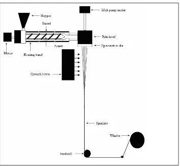
A typical melt spinning process consists ( Figure 4) of an extruder, a positive
displacement pump, a spin head, a spinneret or die, a quench tower, a feed roll, draw rolls,
and a winder. The functions of the extruder are: (1) heat and mix the polymer to produce a
homogeneous melt, and (2) to pump it through the spinneret at a constant rate. The extruder
contains a motor driven screw of a specific length/diameter ratio inside the barrel, which
helps in mixing and pumping of the melt. Generally, there are three zones in an extruder
which correspond to the geometry of the screw: the feed zone, the compression zone, and the
metering zone.3 Each of these zones is heated to different temperatures based on the polymer
being extruded.
Initially, polypropylene granules (MFI= 10-40 g/min) are fed through the hopper into
the extruder feed zone to start melt spinning. Depending on the polymer being extruded, the
chips may be dried or used without prior drying. To prevent the polymer from oxidizing, a
slow nitrogen purge is frequently employed. As the polymer is pushed along the extruder
barrel by either a single or twin screw, it is heated by a combination of conducted heat and
the polymer melt exits the metering zone, the positive displacement pump delivers the molten
polymer at a set flow rate to the spin head.11
Figure 3 Schematic of Melt Spinning 11
The spin head consists of filters and channels that supply molten polymer to the
spinneret, through which the molten polymer is extruded. The filter, composed of a number
screens (or some other special porous materials) , removes degraded polymer gels, foreign
bodies, and gaseous bubbles. After the polymer melt exits the spinneret, a quench tower
pulled down to a smaller cross-sectional area by a feed roll, which is set to a desired velocity.
A set of draw rolls is used before or after the spinning process depending on the final
property requirements of the fiber. Drawing of fibers orients the molecular chains in the
fibers to a high degree in the machine direction. Spun fibers are placed on a bobbin attached
to the winder.
A typical melt spinning process for polypropylene, begins with polypropylene pellets
or granules (MFI= 10-40 g/min) are fed through the hopper to extruder. To melt
polypropylene pellets, the polymer is extruded in the range of 230˚C to 280˚C in several
heating zones.10 The molten polypropylene is then melted and pumped to the spin pack. The
spin pack consists of a filter which removes impurities and uniform melt flow of spinneret
containing small orfices with a diameter of 0.3-0.8 mm. Industrially, a large extruder is used
with a capacity of 500-1000 kg/h to distribute molten polypropylene to 8-20 spinnerets
equipped with separate gear pump and spin pack. The number of spinneret holes for
producing staple fibers is typically 10,000-50,000.15 The molten fiber exits the spinneret and
enters the cooling zone which cools and solidifies the fibers. The shape of the spinneret holes
are round, annular, rectangular, or other various shapes. The shapes of the holes affect the
distribution of quench air flow, appearance of PP fabric, and physical properties of fibers.
The final properties of the fiber, such as percent crystallinity, molecular orientation,
diameter, etc., depend on various processing parameters. The key processing parameters for
melt spinning are the polymer extrusion temperature, the cooling conditions along the
and the shape of spinneret holes. Of all these parameters, two important parameters are
typically recognized by researchers are throughput rate and take-up speed.
1.3.2 Polyolefin Application in Nonwovens
In the past decade, the use of polyolefines, especially polypropylene, has dominated
the production of meltblown and spunbond nonwovens. 1 Polyolefin resins are generally
considered the polymer of choice in the nonwoven market because of the relatively attractive
cost combines with the good value and ease of use in comparison to conventional resins, such
as polyesters and polyamides.
In order to qualify for consideration in nonwoven applications, all polyolefines must
possess extrusion and melt-spinning characteristics. It is well known that polypropylene is
more difficult to extrude than polyethylene. 3 However, both polypropylene and polyethylene
filaments are easy to spin into fine denier filaments provided that resins have narrow
molecular weight distributions and MFI.
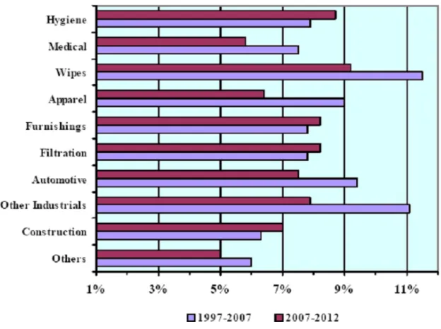
Polypropylene is the most widely used resin in the polymer laid nonwovens. Though
polypropylene nonwovens first gain recognition in the disposable surgical and sanitary
sector, new products are being introduced daily in diverse applications. As shown in Figure
4, nonwovens are used in a variety markets.
Polyolefin polymers are considered material of choice in the absorbent and medical
sector. Of the absorbent product applications, the baby diaper area is the largest volume user;
however, applications in adult incontinence currently show the highest growth in recent
covers, face masks, and sterilizable packaging. Compared to traditional polymers used in
medical
Figure 4 Expected Growth of Nonwovens in Specific Applications1
applications, polypropylene exhibits exceptional characteristics such as breathability,
resistance to fluid penetration, lint-free structure, sterilizability, and impermeable bacteria.
Filtration is a major market for polypropylene nonwovens. In fact, most household
filters are produced from polypropylene nonwovens. In addition to air filtration,
polypropylene nonwovens are used in cigarette filters and numerous technical applications
In packaging applications where paper products and plastic films are not sufficient,
polypropylene nonwovens are used. These applications are food containers, envelopes,
stationary products, and medical sterile packaging.3
Geotextiles, an industry which is highly connected to civil engineering is another
common discipline which polypropylene nonwovens are used. Erosion control, railroad bed
stabilization, canal and reservoir lining protection, highway and airfield black top cracking
prevention, and roofing are unique geotextiles which are composed of polyolefin nonwovens.
The geotextiles are unique and highly controllable structures which are engineered for
specific properties.3
Lastly, polypropylene nonwovens are employed in many areas of the automobile.
One of the major uses of nonwoven webs is the backings of tufted automobile floor carpets.
The nonwovens are also used for trim parts, trunk liners, interior door panels, and seat
covers.
1.3.3 Melt Blown Process for Producing Nonwovens
The melt blowing process is one of the newest and least developed nonwoven
processes. In comparison to other nonwoven processes, the melt blown process is distinctive
because it is used almost exclusively to produce fine fibers rather than fibers the size of
normal textile fibers. The concept of melt blowing to produce fine fibers was first developed
under U.S. government sponsorship in 1954. Van A. Wente, scientist at the Naval Research
Laboratory, first began this work to produce micro-filters for the collection of radioactive
into two converging high velocity streams of heated air or other gas.15 It was claimed that
fibers as small as 0.1 – 1 micron can be formed by this method .16, 17 In the 1960’s, an Exxon
affiliate and a development program recognized the significance of this work. Five years
later, a patented prototype model successfully confirmed the production of fine microfibers
and providing the name for a new process: “Meltblowing”. Thus, Exxon became the first to
demonstrate, patent, publicize, and license the use of the Wente’s concept as a practical
one-step process to manufacture unique forms of nonwoven webs. Early successful licensees
included Kimberly-Clark, Johnson & Johnson, James River, Web Dynamics and Ergon
Nonwovens, followed by many other companies, including 3M. Currently, Exxon has
created the majority of the licenses and/or options to produce microfiber nonwoven and melt
blown equipment.
Meltblowing is an extrusion technology that produces fiber webs directly from a polymer.
The schematic of the process is shown in Figure 5:
Initially, polymer granules or pellets are extruded through a linear die containing
closely arranged small orifices. The filaments are attenuated by two convergent streams of
high-velocity hot air to form fine fibers. After the extruded polymer threads are attenuated by
hot air, this air and resulting fibers are expanded into the ambient air. As a result of the
combination of high speed hot air and fibers with room temperature air, the fiber bundle
starts its movement forward and backward (Figure 6). While flying through the ambient air,
the filaments are stretched and on their way down to the belt the fibers are stretched again
due to so-called “form drag”. This form drag emerges with every change in fiber direction.
Hence, melt blown fibers usually do not have a constant fiber diameter. In general,
fiber attenuation is achieved by three different forces: aerodynamic drag near the die,
aerodynamic drags near the collector, and the fiber elongation due to fiber entanglements
along the spinline; however, most of the attenuation occurs near the die.18 The other function
of hot air streams is also to transport the fibers to a collector where they self-bond at the
Figure 6 Schematic of Fiber Attenuation in the Meltblowing Process15
In most cases, filaments produced by the meltblowing process have generally low or
no molecular orientation .18 Some of the processing conditions which influence the final
properties of the meltblown fibers and webs are melt temperature, polymer mass flow rate
(throughput), die geometry, airflow rate and air temperature, die-to-collector-distance
(DCD), and collector speed.19,20 Variation in any of these input parameters will alter final
properties of fibers, such as cross-sectional shape, diameter, morphology, and web structure
can also be changed.
Melt blowing process has three distinct regimes. The most common regime has a very
high air flow rate that allows production of fibers in the range from 2 to 5 microns. This
regime is currently used commercially. Another regime, the ultra high flow rate regime
allows production of ultrafine fibers with the diameter less than 1 micron. Although fibers as small as 0.1 μm can be produced by the ultra high flow rate regime, it is still under
development . 21 A low air flow rate regime produces 1 denier (approximately 10 μm) and DIE
TIP AIR
KNIFE AIR KNIFE
ROOM AIR HOT AIR
larger fibers.22 The effort to produce sub-micron fibers by using splittable cross-sectional
fiber morphology in the meltblowing process was attempted however the smallest achieved
fiber diameter was generally in the range of 1 – 2 microns.23, 24
Meltblown webs usually have a wide range of product characteristics. The main
characteristics and properties of melt-blown webs are as follows: 25
1. Random fiber orientation.
2. Lower to moderate web strength, deriving strength from mechanical entanglement and frictional forces.
3. Generally high opacity (having a high cover factor).
4. Fiber diameter ranges from 0.5 to 30 µm, but typically from 2-8 µm. 5. Basis weight ranges from 8-350 g/m2, but typically 20-200 g/m2.
6. Microfibers provide a high surface area for good insulation and filtration characteristics.
7. Fibers have a smooth surface texture and are circular in cross-section.
8. Most melt-blown webs are layered or shingled in structure, the number of layers increases with basis weight.
Nonetheless, there are few drawbacks to the meltblowing technology. One drawback is,
only low viscosity materials can be spun into meltblown webs to avoid excessive polymer
swelling upon exit from the spinneret. As a result, it is estimated that over 90% of all
meltblown nonwovens are made of polypropylene having melt flow rate (MFR) ranging from
1000 to 1500 g/10 min.27 Due to the lack of ability to employ different polymers in
meltblowing, many potential applications of the meltblown web are limited. Another
fibers typically need a supporting structure and are generally engaged in a composite
structure.29 This allows for the meltblown web to optimize their filtration properties;
however this adds the complexity to the manufacturing process. The brittleness of meltblown
webs causes difficulties with their downstream processing also. In general, meltblown fabrics
are difficult to dye and incorporate into other nonwoven filter media structures, such as
carded, airlaid, needlepunched, or wetlaid composites. As a final point, meltblown webs
typically exhibit broad fiber diameter distributions that can be inappropriate for some
applications.30 1.3.4 Spunbond Process for Producing Nonwovens
The spunbonding process is a manufacturing system involving direct conversion of a
polymer into continuous filaments, integrated with the conversion of filaments into a
random-laid, bonded nonwoven. 26 A spunbonded nonwoven is defined as a fabric formed by
filaments that have been extruded, drawn, laid on a belt, and bonded thermally, chemically or
mechanically. Historically, the spunbonding process can be viewed as either an evolution of
the existing staple fiber nonwoven production concept or the logical extension of the
synthetic filament spinning processes commercialized during 1940s and 1950s.27 The
spunbonding process is considered to have originated in 1940, when the processes similar to
that of spunbonding were patented by Slather and Thomas of Corning Company for the
production of glass wool.28 Similar processes for the manufacture of the mineral wool from
molten silica were patented by Callender in 1945.29 Commercially, manufactured
spunbonded nonwovens made of synthetic polymers are commonly based on the technology
DuPont commercialized a product made of polyester called Reemay®. This was followed by
Typar® made of polypropylene and Tyvek® made of high-density polyethylene produced by
flash-spinning method.31 During the same time period, Freudenberg introduced the
spunbonding process called Lutravil® for the manufacture of mixed polyamides. A few years
later a process called Docan® was introduced by Lurgi Kohle & Mineral öltechnik GmbH
(Germany). In 1984, the spunbonding process called Reicofil® for producing webs from
polypropylene was introduced by Refenhauser GmbH (Germany).31 Within the1990s other
equipment suppliers, such as Kobelco, Nordson, STPI, ISBT (now Rieter), Hills,
Inventa-Fisher and many others offered complete spunbond lines, and hygiene and medical suppliers switched to spunbond (meltblown) processes. In 2000’s, Reifenhauser became the main
turnkey supplier of spunbonds polypropylene. Also, in 2000’s Reifenhauser and Nordson
offered bicomponent spunbond and meltblown using Hills bicomponent technology. Hills
offered Hills open system spunbond with Hills biotechnology.
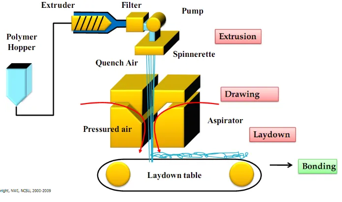
A primary factor in the spunbonding process is the control of five operations:
filament extrusion, drawing, quenching, lay down, and bonding. The typical spunbonding
process consists of the following elements: a polymer feed, an extruder, filament spinning,
drawing and deposition system, quenching, laydown, and bonding.32 The schematic diagram
Figure 7 Spunbond Process1
In spunbonded fibers, also called air attenuated fibers, the polymer is fed to the
extruder in the form of a powder or pellet. In addition to the polymer, stabilizers, additives,
color master batch, resin modifiers etc. may also be fed through the extruder. As the polymer
moves through the extruder, it is exposed to heating, friction of viscous flow, and mechanical
action resulting in melting. Periodically, vented twin-screw extruders are used to dry the
polymer as it melts. Under pressure, the molten polymer is then transported to a filter. The
purpose of the filter is to remove foreign particles, such as metals, solid polymer particles,
etc. from the molten polymers. After filtering, the polymer melt goes to a metering pump.
The metering pump is a positive displacement constant volume device that controls a precise
volumetric flow rate of the molten polymer. The melt pumps provide high pressure for the
spin pack. From the gear pump the polymer melt goes to a spin beam, which includes the
a die block assembly (spin pack), one of the most important elements of the spunbonding
process. The die assembly, consists of a polymer feed distribution plate and a spinneret. The
feed distribution in the die assembly is very vital because it balances the polymer flow and
the residence time across the width of the die. It provides a uniform polymer distribution to
each capillary and a uniform temperature of the polymer flow. From the feed distributor, the
polymer melt goes into the spinneret. The spinneret is a single block of metal having several
thousand orifices, which can have different shapes, but usually circular or rectangular in
shape. Commercially, several grouping of spinnerets (blocks) are used to increase the
coverage of fibers. As the filaments surface through the spinneret holes, they are forced
downward into quench zone or quench chimneys. As the filaments travel through the quench
zone, cool air is directed across the filament bundle to cool the molten filaments and cause
solidification. Because insufficient solidification results in the fiber roping and inability of
the fibers to form the web, efficient quenching of the filaments is very important. After
quenching, the filaments are led downward into a tapered medium by the air stream. A
second stream of the high-velocity air is directed parallel to the direction of the filaments,
causing acceleration and accompanying attenuation of the individual filaments.26 However, it
has been shown that filament attenuation starts right below the spinneret exit.27,33-36
After attenuation and quenching, the filaments are deposited on a moving belt.
Vacuum under the belt assists in the formation of the filament web on the forming belt and in
removal of air used in the extrusion/drawing operation. To achieve maximum uniformity and
cover in the web, individual filaments are separated prior to placement on the belt. In some
separation of the individual filaments. In other cases, deflector plates are used to lay down
the filament sheet on the forming belt. The collecting belt surface is usually perforated to
prevent the air stream from deflecting and carrying the fibers in an uncontrolled manner.
Finally, the continuous filament web is delivered to a bonding section. At the bonding
section, one of several methods could be applied to bond loose filaments into strong,
integrated fabric, such as calendering, hydroentangling, needlepunching, ultrasonic bonding,
through air thermal bonding, stitch bonding, or chemical bonding. In commercial production
lines, bonded fabric encounters finishing (topical treatments, dying, embossing, laminating,
stretching, splitting and so on) and slitting sections. Following slitting, the fabric is wound
onto a large roll, either a full width roll or series of narrow slit rolls. At this point, the fabrics
are ready for wrapping and shipping.26
The spinning speeds during spunbonding can range from 1,000 to 8,000 m/min,
depending on the processing polymer characteristics, desired properties of resulting fiber,
and process productivity.26 Some polymers show a higher degree of molecular orientation
and crystallinity due to stress induced crystallization at higher spinning speeds. However,
polypropylene does not show significant improvement in the molecular orientation with an
increase in the spinning speed due to its high crystallizing ability.36 Thus, polypropylene
usually spins at about 2000 m/min. Properties of polypropylene spunbonds include high
strength, low weight, hydrophobicity, good skin tolerance, chemical and rot resistance, and
1.3.5 Need for Biodegradable Nonwovens
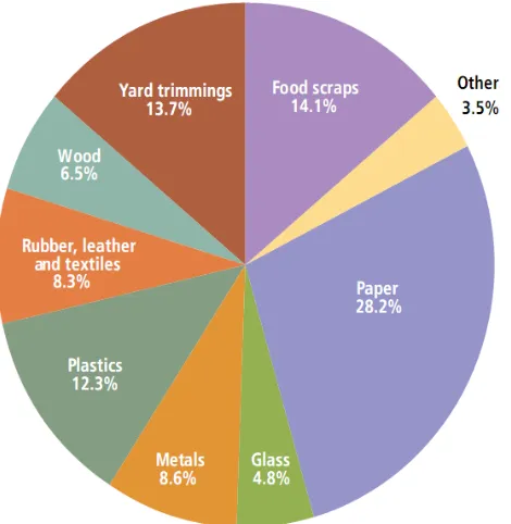
According to the United States Environmental Protection Agency, Americans
produced about 243 million tons of municipal solid waste (MSW), or about 4.3 pounds of
waste per person per day in 2009. The graph below illustrates the material breakdown of the
waste generated. As depicted below (Figure 8), approximately 8.3% of leather, rubber, and
textiles were disposed. Hence, nonwovens are categorized as textiles.
Figure 8 Material Breakdown of Waste Generated by Americans in 200937
Since the initial production of nonwovens more than 2 decades ago, the nonwoven
success of the nonwoven market is attributed to the small labor requirement, high spinning
speed, and low cost. Globally, the nonwovens market (Figure 9) has continued to expand year after year with the exception of 2008 due to economic downturn.38
Figure 9 Amount of Nonwovens Produced Globally38
Over half of the production of nonwovens is populated in North America (mainly the
United States) and Europe as shown in Figure 10. However, as the cost of shipping increase,
developing countries such as China and Latin America are expected to increase in
production. 0 1 2 3 4 5 6 7 8
2000 2001 2002 2003 2004 2005 2006 2007 2008
Figure 10 Percentage of Nonwovens Produced Globally 1
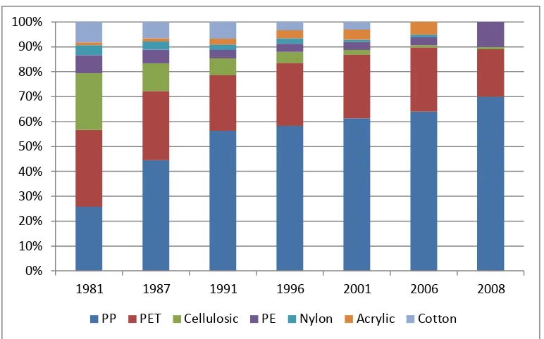
Synthetic fibers have dominated the nonwovens industry for decades. Since the
1980’s, polypropylene has become the polymer of choice to manufacture nonwovens. In
particular, polypropylene is employed in home filters, hygiene products (diapers, feminine
pads) and medical filters. In these applications, the product is typically used once and then
disposed in the designated waste stream. Consequently, 64% of nonwovens in 2001 have a
shelf-life of less than one month. With the consumption of nonwovens increasing annually,
alternative methods must be explored for waste disposal.
South America 4%
4% Middle
East 4% Other
2%
Japan 6%
Asia Pacific 10%
Europe 29% China
20%
Figure 11 Polymers Used in Nonwovens Since 198138
In the 21st century, nonwoven producers have expressed concern about the
sustainability of nonwovens. In general, biodegradability jumps to the forefront as an
environment concern when the tremendous growth in nonwoven production and consumption
is not likely to slow down in the next decade. Rising standards of living and increased
disposable income allocated to health and hygiene are leading to a significant increase in the
demand for nonwoven products.
0% 10% 20% 30% 40% 50% 60% 70% 80% 90% 100%
1981 1987 1991 1996 2001 2006 2008
Figure 12 Lifetime of Nonwovens39
Thus, discovering a method to locate renewable, biodegradable products has
been a challenge facing the disposable side of the nonwovens industry from Day 1.
Diapers, feminine hygiene products, wipes and other disposable items have long been
criticized for their contribution to landfills despite studies deeming it insignificant,
and the whole "disposing of disposables" debate has been a hot one among
nonwovens stakeholders. However, a few companies have begun addressing the
urgency to create nonwovens which naturally degrade when disposed in the landfill.
In recent years, Ingeo Fibers has been making considerable strides in the area
of sustainable, renewable products involving nonwovens and other textiles. The
company's biopolymer NatureWorks PLA is the world's first greenhouse-gas neutral
polymer and forms the basis for Ingeo fibers, which has replaced
polypropylene-based on oil, a limited resource-in some disposable applications. Because
NatureWorks PLA resins and Ingeo fiber are derived from 100% sustainable
use. Ingeo has uniquely positioned the products to replace existing oil-based polymers
and fit perfectly with both the consumer and legislative demand for a sustainable
approach to handling disposable products.
Among the nonwoven products currently being manufactured with the Ingeo
Fibers are W.I.P.'s (Wellness Innovation Project) biodegradable Love 'N feminine
hygiene products and Eco Baby wipes developed by Healthquest. Other potential
applications of Ingeo Fibers include furniture and mattress waddings, short life
industrial applications, diapers and many more nonwoven products. Because these
applications contribute to significant waste management issues, Ingeo fiber is an easy
drop-in alternative that offers a competitive choice from all
perspectives-performance, economics and not least, ethics.
Ingeo fiber and NatureWorks PLA resin is produced in a comprehensive range
of resin and fiber types designed to fit with standard nonwovens technologies ranging
from spunbonding and spunlacing to thermal, chemical or resin bonding, calendering,
needlepunch and wetlaid processes.
Cellulosic fiber supplier Lenzing also recognizes the need for sustainability in
the nonwovens industry. Lenzing fibers are fully biodegradable and become part of
the natural cycle. Cellulose fibers are made from pulp, which is made from wood, a
renewable and climate-friendly resource. Nonwovens made Lenzing fibers are fully
biodegradable and become part of the natural cycle. Under the trademarks Viscose®
DIN CERTCO, which issues certificates only for products fully made from
compostable raw materials.
Though several studies have explored biopolymers as alternatives to synthetic
polymers to construct nonwovens, polypropylene still remains a strong candidate in
nonwoven fabrication. Despite the fact that polypropylene breakdown after a 100
years in the landfill, biopolymers have several drawbacks when used in nonwoven
applications. A few of the limitations to biopolymers are:
1. The shelf-life is very short.
2. Production cost and bioresins are expensive.
3. Insufficient mechanical and thermal properties.
4. Industrial composting facilities are not readily available to handle
tremendous waste from biopolymers.
Thus, the objective of this research is to study waste disposal alternatives to alleviate
polypropylene nonwovens at the end of service life. Instead of disposing polypropylene
nonwovens in the landfill, the current research examines the feasibility of composting virgin
and chemically modified polypropylene at specific conditions.
1.4 Degradation Mechanisms of Polypropylene
Degradation of polymers is defined as any change in polymer properties due to
change in chemical, physical, or biological reactions resulting in bond scission or subsequent
chemical transformations .40 Degradation is often categorized as changes in material
properties such as mechanical, optical, thermal, or physical properties in the form of
result in chain scission, chemical transformation, or attachment of new functional groups.
Depending on the nature of the polymer, degradation (Figure 13) may occur by
photo-oxidative degradation, thermal degradation, ozone-induced degradation, catalytic
degradation, or biodegradation. Many studies have documented the degradation of
polypropylene by photo-oxidative degradation, thermal degradation, oxo-biodegradable
degradation, and biodegradable.
Figure 13 Various Polymer Degradation Routes40
1.4.1 Photo-oxidative Degradation of Polypropylene
Photo-oxidative degradation is the process of decomposition of a material by the
action of light, which is considered as one of the primary sources of damage exerted upon
polymeric substrates at ambient conditions.41 Most synthetic polymers are susceptible to
spectrum (Figure 14) shows the location of UV and visible light. In the UV region, the
UV-B terrestrial radiation (~295–315nm) and UV-A radiation (~315–400nm) are responsible for
the direct photo-degradation (photolysis, initiated photo-oxidation) of synthetic polymers. In
the visible portion, sunlight (400-760nm) accelerates polymeric degradation by heating.
Figure 14 Electromagnetic Spectrum
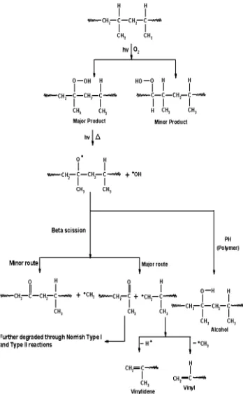
Polymer degradation occurs mainly in the ether groups, where photo-irradiation
generates ester, aldehyde, formate, and propyl end groups . 42 UV radiations have sufficient
energy to cleave C-C bond .43 The most damaging UV wavelength for a specific plastic
depends on the bonds present and the maximum degradation, around 320 nm for
polypropylene. During photo-oxidation, the polymers physical, mechanical, and optical
properties change. Visually, the polymer may appear yellow in color or fading maybe
observed. Thus, mechanical integrity is diminished and molecular weight is decreased as a
result of extensive chain scission during photo-degradation.41
chain reactions involving free radicals as described by the Bolland-Gee autooxidation
mechanism.44 Thus, photo-oxidative degradation of polypropylene involves initiation,
propagation, and initiation.
The photo-oxidative degradation of polypropylene is initiated by abstraction of
hydrogen atoms from the aliphatic chains by singlet oxygen molecules.3 In general, the
hydrogen atoms attached to tertiary carbon atom are the most readily abstracted. Hence,
without the tertiary carbon atom, photo-oxidative degradation of PP would not transpire
because polyolefin polymers do not absorb UV-radiation in the solar spectrum at the earth
surface.45 For that reason, once initiated the chemical degradation takes place through an
autocatalytic process that is diffusion controlled. As the initiation reaction occurs,
hydroperoxides form from the decomposition of impurities.
After initiation, a series of propagation reactions occur from which further hydroperoxides