Transactions, SMiRT-22
San Francisco, California, USA - August 18-23, 2013 Division III
COMPUTATION OF WELDING RESIDUAL STRESSES IN
A MULTI-PASS WELDED MOCK-UP PIPE
Heikki Keinänen1, Michael Chauhan2
1
Senior Scientist, Structural Performance, VTT Technical Research Centre of Finland (Heikki.Keinanen @vtt.fi)
2
Research Scientist, Structural Performance, VTT Technical Research Centre of Finland
ABSTRACT
In on-going MACY-project residual stresses are measured from a multi-pass welded mock-up pipe. Computational simulation of welding will provide one independent result for the residual distribution. The computation was performed with the Abaqus finite element code. Both axisymmetric and three dimensional models were utilised. The non-linear characteristics of the material including temperature dependency and plasticity were taken into account. The computed size of the fusion zone is reasonable, which is verification for the thermal results. The axisymmetric model gave a larger fusion zone near the inner surface. The computed axisymmetric and three dimensional stresses show a formal agreement with each other. The axisymmetric model gave higher circumferential stresses near the inner surface. This is most probably partly due to thermal results and partly due to the lack of capability of the axisymmetric model to model the movement of welding torch in the circumferential direction and consequently deformations in front of and behind the torch are ignored. A comprehensive comparison of the computational results to the measured ones will be performed in future.
INTRODUCTION
A mock-up of a pipe containing multiple butt-welds was manufactured, and residual stresses are measured with various methods from the pipe. The pipe mock-up is shown in Figure 1. The outer diameter and wall thickness of the pipe are 323.85mm and 17.45 mm correspondingly. The length of the mock-up is 400 mm consisting of two equally length pipes which are welded together. The pipe materials are austenitic steel SA 376 TP 304, and weld material AISI 318L. The welding was performed by nine passes. The first three passes were welded using gas tungsten arc (TIG) welding and the rest of the passes were welded using manual metal arc welding. Table 1 shows the welding parameters, and Figure 2 welding passes. The welding velocity was computed as an average utilising the given average circumferential welding duration and time values.
Figure 1. The pipe mock-up.
Table 1: The welding parameters. The velocity was the computed average velocity using the given welding time and length.
Pass Voltage [V] Current [A] Velocity[mm/s] Temperature
before start [°C]
1 13.5 84.0 0.3289 25
2 13.5 90.0 0.3777 55
3 13.5 90.0 0.4080 57
4 22.0 77.0 1.1485 22
5 22.0 77.0 0.8958 64
6 22.0 100.0 1.2386 21
7 22.0 100.0 1.1923 70
8 22.0 100.0 1.4570 48
9 22.0 100.0 1.6201 88
MATERIAL PROPERTIES
22nd Conference on Structural Mechanics in Reactor Technology San Francisco, California, USA - August 18-23, 2013 Division III
Figure 2. Welding passes.
Figure 3. Specific heat and conductivity as a function of temperature. The properties for 304 were taken from Zang et al. (2009).
Figure 5. Computed stress-strain curves for the parent and weld material. The data is shown for the first cycle, strain amplitude is 0.05.
DESCRIPTION OF THE ANALYSIS PROCEDURES
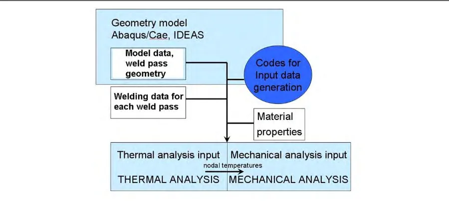
Abaqus 6.11-1 software was utilised in the analyses. Thermal and mechanical analyses were performed separately. In-house codes were used to generate some of the input data, see Figure 6. First order (linear) reduced integration hybrid finite elements were used in order to avoid volumetric locking (Abaqus solid element type C3D8RH or axisymmetric type CAX8RH). Small strains and displacements were assumed.
In the mechanical analysis additional dummy elements were doubled upon the structural elements used in the weld area. These dummy elements were modelled with low elastic modulus and material strength properties. The dummy elements were needed to track the accumulated deformation of the nodes, which are not yet active in the model. Otherwise the computed deformed shape would be highly distorted. The dummy elements were not present in thermal analysis.
In the mechanical analysis, mixed hardening material model of Abaqus including both isotropic and kinematic hardening with an anneal temperature of 1000 °C was utilized, Armstrong and Frederick (1966), Chaboche (1989).
22nd Conference on Structural Mechanics in Reactor Technology San Francisco, California, USA - August 18-23, 2013 Division III
Figure 6. Flow chart of the analysis procedure.
Table 2: Welding data from the three dimensional FE analysis including also computed pass volume and heat input.
In the thermal analysis the heat input was modelled using uniform internal heat generation and an exponential time function. The length of the time function was chosen so, that the length of the heat input area was approximately 12 mm. In addition, the initial temperature of 1400 °C of the weld material was modelled. The amount of the heat input Q [J/s]), was obtained using the welding parameter, and thermal efficiency as:
Q
U I
, (1)where U is voltage and I is current.
Concerning surface heat losses convection was modelled. The ambient temperature was 20 °C. No heat losses from weld pool were modelled. Radiation was not modelled.
Pass Thermal Efficiency [%]
Volume [mm3]
Heat Input [J/mm3s]
1 80 109.5 5.79
2 144 143.7 8.53
3 160 171.8 9.66
4 96 112.6 13.17
5 96 111.36 13.41
6 120 146.42 11.95
Figure 7. Real welding process sequence (left figure), and the modelled sequence in the three dimensional FE analysis (right figure).
COMPUTATIONAL MODEL
On the basis of the preliminary results it became apparent that a 45 degree model is too small in the circumferential direction. The effects of the boundaries were visible on the results. Thus a 90 degree model was constructed, see Figure 8.Symmetry conditions were assumed on the axially oriented cutting planes. One point on the end plane was fixed in the axial direction to prevent rigid body movement. In the final model, the number of nodes was 59902 and the number of elements was 54420. The element side length varied between 0.6…2.2 mm in the weld area.
22nd Conference on Structural Mechanics in Reactor Technology San Francisco, California, USA - August 18-23, 2013 Division III
In addition to the mechanical boundary conditions thermal convection boundary conditions were assumed. Convection due to surface heat losses was modelled using a convection coefficient of 30 W/m2K. The heat flow in the circumferential direction was modelled using a convection coefficient of 60 W/m2K.
For comparison the analyses were performed also using an axisymmetric model, Figure 9. In the axisymmetric model the welding is assumed to be performed instantaneously around the circumference. Reduced integration hybrid element type CAX8RH (Abaqus (2011)) was utilised in the computation. In the weld area the minimum element side length was 0.45 mm. The number of nodes was 6861 and elements 2182. Convection due to surface heat losses was modelled using a convection coefficient of 20 W/m2K.
Figure 9. The axisymmetric finite element model.
RESULTS
Figure 10 shows computed temperatures during the welding of bead 6. The molten (grey) area of the moving heat source is visible in the Figure.
The computed maximum deformation in the middle of the weld is approximately 2 mm. The computed deformed shape is basically similar to that of the mock-up. Figure 11 and Figure 12 show the computed circumferential residual stresses after welding. Both three dimensional and axisymmetric results are shown. Larger tensile stresses were obtained with the axisymmetric model in the weld area near the inner surface.
Figure 13 shows the computed through-wall stress distributions at the middle of the weld. The differences between the three dimensional and axisymmetric circumferential (hoop) stress results are clearly visible near the inner surface.
Figure 10. Computed temperatures during the welding of bead 6.
22nd Conference on Structural Mechanics in Reactor Technology San Francisco, California, USA - August 18-23, 2013 Division III
Figure 12. Computed circumferential residual stress (MPa) after welding, axisymmetric model.
Figure 13. Computed axial and circumferential (hoop) residual stress (MPa) after welding at the middle of the weld. Three dimensional and axisymmetric results are shown. Inner surface corresponds to coordinate
three dimensional model were utilised. The non-linear characteristics of the material including temperature dependency and plasticity were taken into account.
Considering the computation of the welding, the weld pass lumping was a powerful method to simplify the computation procedure. However, the final weld passes were individually modelled to get adequate results. The computed size of the fusion zone is reasonable, which is verification for the thermal results. The axisymmetric model gave a larger fusion zone near the inner surface.
The computed axisymmetric and three dimensional stresses show a formal agreement with each other. The axisymmetric model gave higher circumferential stresses near the inner surface. This is most probably partly due to thermal results and partly due to the lack of capability of the axisymmetric model to model the movement of welding torch in the circumferential direction and deformations in front of and behind the torch.
A comprehensive comparison of the computational results to the measured ones will be performed in future.
ACKNOWLEDGEMENTS
This work has been carried out in the FRESH project of the SAFIR2014 programme (The Finnish Research Programme on Nuclear Power Plant Safety). The project has been funded by Valtion ydinjäterahasto, VTT and TVO (Teollisuuden Voima Oyj). The authors are grateful for comments obtained from the members of the SAFIR2014 Reference Group 6 and from Paul Smeekes/TVO.
REFERENCES
Abaqus Theory Manual, version 6.11-1. Dassault Systemes, 2011.
Armstrong, P.J. & Frederick, C.O. A mathematical representation of the multiaxial Bauschinger effect,
C.E.G.B. Report RD/B/ N731, Berkeley Nuclear Laboratories, Berkeley, UK, 1966. Chaboche J L 1989 Int. J. of Plasticity 5 247.
Ku F.H. & Tang S.S. 2012. Investigative study of 2-D vs. 3-D weld residual stress analyses of the NRC phase II mockup. Proceedings of the ASME PVP 2012, July 15-19, 2012, Canada. 7 p.