Jurnal Teknologi, 44(A) Jun 2006: 115–125 © Universiti Teknologi Malaysia
THE DESIGN AND SIMULATION OF FLOW MODE ELECTRORHEOLOGICAL DAMPER
REIZA ZAKIA MUKHLIS1, NIK ABDULLAH NIK MOHAMED2 & MOHD JAILANI MOHD NOR3
Abstract. Electrorheological (ER) damper is a damper that utilizes electrorheological fluid as the working fluid. By changing the strength of applied electric field to the fluid, the flow resistance of the fluid changes and hence the damping characteristic could be adjusted. This paper provides theoretical formulation to calculate the damping constant of semi-active flow mode ER damper. The formula is developed by analyzing fluid velocity profile that flows in electrode gap. From the simulation, it shows that electric field strength gives severe effect to the damping level of the damper. Without applying electric field, a reduction on the gap of electrode from 3 to 1 mm will increase the damping constant value by a factor of only 27, while with a 3 kVmm–1 electric field being applied, the increase is by a factor of 595.
Keywords: Vehicle suspension, electrorheological damper, electrode gap
Abstrak. Peredam elektroreologi (ER) adalah peredam yang menggunakan bendalir elektroreologi sebagai bendalir kerja. Dengan mengubah kekuatan medan elektrik yang diberikan kepada bendalir ER, ketahanan alir daripada bendalir tersebut berubah dan kerananya ciri redamannya dapat dilaras. Kertas kerja ini menyediakan perumusan teori untuk menghitung pemalar redaman daripada peredam separa aktif ER ragam alir. Rumusan tersebut diterbitkan melalui analisis daripada profil halaju bendalir yang mengalir di dalam sela elektrod. Daripada hasil simulasi, didapati bahawa kekuatan medan elektrik memberikan pengaruh yang sangat besar terhadap tingkat redaman daripada peredam. Tanpa pemberian medan elektrik, pengurangan sela antara elektrod daripada 3 mm kepada 1 mm akan menaikkan nilai pemalar redaman sebesar 27 kali ganda sahaja. Manakala dengan pemberian medan elektrik sebesar 3 kVmm–1, nilai pemalar redaman meningkat sebanyak 595 kali ganda.
Kata kunci: Ampaian kenderaan, peredam elektroreologi, sela elektrod
1.0 INTRODUCTION
In the design of vehicle suspension system, there must be a compromise between two conflicting requirement, which are road handling and ride comfort. To get a good ride comfort, lightly damped suspension is needed. On the other hand, heavily damped suspension is needed to get good handling. Since the road condition is random in nature and may vary from one profile to another, the optimum performance
1,2&3
of the suspension system can only be obtained using damper with adjustable damping characteristic. There are two ways to adjust the damping level, whether controlling the fluid properties or modifying the orifice.
Electrorheological fluid is a class of dispersion which is commonly composed of polarisable solid particles as dispersion phase and non conducting oil as dispersed phase. Upon the imposition of external electric field, the particle will polarised and form a chainlike structure along the directions of the electric field. This structure is responsible for the rheological properties alteration of the ER fluid from a fluid-like state to a solid-fluid-like state which exhibits a yield stress. The reversible and dramatic change in the rheological properties of ER fluids coupled with the instant response made the fluid suitable to be used as working fluid for the system mentioned above.
2.0 DESIGN CONCEPT OF INTELLIGENT SUSPENSION SYSTEM
An intelligent suspension system which utilize ER damper has been proposed by Mukhlis et al. [1], as shown in Figure 1.
Figure 1 Schematic diagram of an intelligent ER suspension system [1] Processing Control
system
Processing
Electric source
ERF damper Actual
damping level Desired damping
level Sensor Road
profile
Sensor
Suitable damping level
semi-active system since it can only dissipate energy but cannot inject energy to the system.
The damper used in the system is flow mode-ER damper. Flow mode is chosen since this mode gives higher yield stress than shear mode for the same electric field strength applied [2]. The relationship between electric field strength to the yield stress and damping constant of the damper is discussed in the following section.
3.0 MATHEMATICAL MODEL
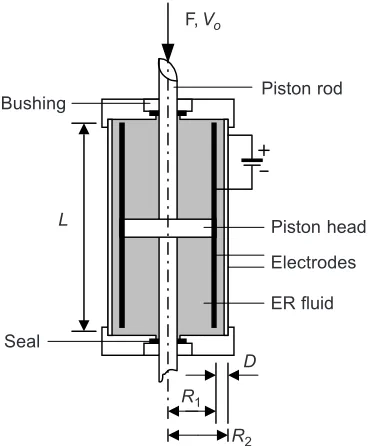
Basically, the flow mode ER-damper consists of piston rod and piston head in concentric cylinder tubes which also act as electrodes (Figure 2). If a certain level of force is given to the piston rod, there will be a pressure drop between the upper section and the lower section inside the annular gap and the fluid will move with a certain flux or velocity.
Figure 2 Flow mode ER damper Piston rod
Piston head
Electrodes
ER fluid Bushing
Seal
L
D R1
R2
In the case where electrode gap (D) is much less than inner electrode diameter (2Rl), the solution for the Poiselle flow between concentric cylinders collapses to that flow between parallel plates [3]. For the fluid between parallel plates, the force equilibrium is [4]:
d P
dr L
τ = ∆
(1)
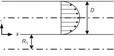
where τ is the shear stress, L is the electrode length and ∆P is the pressure drop. Without the application of external electric field, the particle phase of ER fluid is randomly distributed in dispersed phase and act as Newtonian fluid (Figure 3).
The shear stress of Newtonian fluid is proportional to the velocity profile gradient through the gap as:
0 du dr
τ µ= (2)
where µ0 is the viscosity and u is the velocity.
Figure 3 Schematic illustrations of the ER particles before and after application of an electric field. The two parallel dark lines stand for two electrodes [5]
E E
The equation for the velocity profile (Figure 4) can be obtained by substituting Equation (2) to Equation (1) and integrating with respect to r, as:
( )
(
2)
0
2
P
u r r Dr
µ ∆
= − (3)
By inserting the non-slip condition at the boundary such that u(0) = u(D) = 0, yields
( ) (2 )
2
P
r r D
L
τ = ∆ − (4)
Figure 4 Newtonian fluid velocity profile
D
x r
The fluid volume flux through the electrodes (QN) is obtained via integrating the velocity profile over the annular electrode gap, which is:
π µ
∆ = − 1 3
0
6 N
R D P Q
L (5)
The fluid volume flux through annulus (QN) is equal to the fluid volume flux displaced by the piston head (Qp). Since Qp = Apv0 and ∆P = −F/Ap, yields:
2 0 0 3 1 6 p A L F v R D µ π = (6)
By noting that F = CNv0, gives:
2 0 3 1 6 p N A L C R D µ π = (7)
In the above equations, Ap, CN and v0 are area of piston head minus area of rod, zero-field damping constant and piston head velocity respectively.
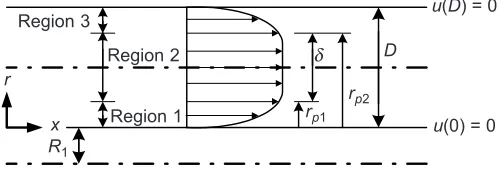
If a certain amount of electric field strength is applied to ER fluid, the particle phase of the fluid will polarize and form a chainlike structure between the electrodes (Figure 3). The fluid will only flow if the stress given is greater than a critical point called yield stress, τy. This condition can be modeled by Bingham plastic behavior as: sgn y p du du dr dr τ τ= =µ
(8)
The higher electric field strength (E) applied, the higher τy will be produced. The relationship between E and τy is [6,7]:
( ) 2
y E E E
τ =α +β +χ (9)
where α, β and χ are the characteristic value for the particular ER fluid which are obtained via experiment.
Figure 5 Bingham fluid velocity profile Region 3 Region 2 Region 1 R1 x r rp1 δ rp2 D
u(D) = 0
The velocity profile of Bingham flow can be divided into three regions (Figure 5). Regions 1 and 3 are called post yield conditions while region 2 is called as pre yield condition. On regions 1 and 3, τ is higher than τy so that the material is sheared. On the other hand, τ in region 2 is lower than τy so that the material will flow as a plug.
From the integration of Equation (1), shear stress in region 2 is:
2 1
P r C L
τ = ∆ + (10)
By inserting boundary condition such that τ(rp1) = τy and τ(rp2) = –τy yields:
1 1
y p
P
r C L
τ = ∆ + and y p2 1
P
r C L
τ ∆
− = + (11)
Subtraction of these equations yields equation for plug thickness as:
2 1 2 y p p p A L r r F τ δ
− = = (12)
By introducing non dimensional plug thickness
D
δ
δ = and noting that rp2 – rp1
= δ and gives equations:
(
)
1 1
2
p D
r = −δ (13)
(
)
2 1
2 p
D
r = +δ (14)
Substituting Equation (8) into Equation (1), integrating it with respect to r and inserting boundary condition such that shown in Figure 5, yields velocity profile equations for each region as:
( )
1 p1
p P
u r r r
L
µ ∆
= − (15)
( )
µ ∆
= − 2
2 1
2 p p
P
u r r
L (16)
( )
(
2 2)
3 2 2 2 2
2 p p p
P
u r r r r r D D
L
µ ∆
= − + − (17)
by integrating fluid velocity profile for the whole regions with respect to r yields equation for volume flux of Bingham flow as:
(
) (
)
π δ δ
µ ∆
= 1 3 1− 2 2+
since ∆ = −P F / Ap, gives:
(
) (
)
(
)
2 1 2 0 3 1 12 1 2 p p B LA F v R D µ δ δ π −= − + (19)
so that the damping constant is:
(
) (
)
(
)
2 1 2 3 1 12 1 2 p p B LA C R D µ δ δ π −= − + (20)
For Newtonian condition (E = 0 and δ =0), Equation (20) is similar with Equation (7).
All preceding equations are valid for the assumption that the flow is steady and laminar and the viscosity of the fluid remains constant at working temperature. The complete equation can be found in [8].
4.0 RESULTS AND DISCUSSIONS
Several simulations have been done by using some commercially available ER fluid: Al 3565 (made by Bayer AG Germany), TX-ER5 (made by Nippon Shokubai, Co., Ltd. Japan) and ER-100 (made by Lord Corp. USA). The viscosity of the fluids at 25°C are 66.13, 48 and 220.31 mPa respectively. The nominal damper design is: L is 101.6 mm, R1 is 25.4 mm, piston head diameter is 50.8 mm, and electrode gap is 2 mm.
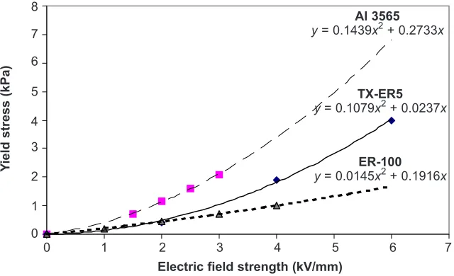
The relationship between electric field to the yield stress for each fluid is obtained from data in [9] and shown in Figure 6.
Figure 6 Effect of electric field strength to the τy 8
0
Al 3565
y = 0.1439x2 + 0.2733x
Y
ield stress (kPa)
TX-ER5
y = 0.1079x2 + 0.0237x
ER-100
y = 0.0145x2 + 0.1916x
1 2 3 4 5 6 7
2 3 4 5 6 7 1 0
The damping constant produced by the nominal damper filled up with each fluid is shown in Figure 7. The damping constant is obtained by substituting the dimension of the damper and the fluid properties to Equations (8), (12) and (20).
Figure 7 Relationship between electric field strength to the damping constant for nominal damper filled up with particular fluid
2500
0
Al 3565
Damping constant (Ns/m)
ER-100
TX-ER5
0.5 1 1.5 2 2.5 3 3.5 500
1000 1500 2000
0
Electric field strength (kV/mm)
4 4.5
From Figure 7, it can be concluded that the damper filled with Al 3565 has the widest controllable range. This condition prevail since the fluid has low viscosity at zero field condition and has the highest yield stress in the application of external
Figure 8 Force versus velocity diagram for nominal damper filled up with Al 3565
Force (N)
Piston velocity (m/s)
4kV/mm
0.1
3kV/mm
2kV/mm
1kV/mm 0kV/mm
0.3 0.5 0.7
–400
–800
–1200 400
800
–0.1 –0.3
–0.5 –0.7
electric field. For the application of electric field strength up to 4 kVmm–1, the damping constant produced by Al 3565 is in the range between 250 to 2000 Nsm–1. The following discussion is focused on damper that is filled up with Al 3565 fluid.
Figure 8 shows the relationship between force versus piston velocity for each electric field strength applied. For a given electric field strength, the applied load must exceed a minimum force before the piston starts to move. From Figure 8, it can be seen that for a given piston velocity, the damping force for 4 kVmm–1 electric field strength applied is higher by a factor of 7 compared with zero-field condition. The higher this difference factor, a wider controllable range for the semi-active damper will be obtained.
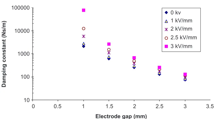
Figure 9 shows the effect of electrode gap variation to the damping constant for nominal damper design filled up with Al 3565 in logarithmic scale. The damping constant appears to be very sensitive to the gap dimension. In zero-field condition, as the gap tapered from a maximum of 3 mm to a minimum of 1 mm, the damping level increase by a factor of 27. It increases from 75 to 2000 Nsm–1. This trend becomes even more severe as the applied electric field increase to 3 kVmm–1. In the application of 3 kVmm–1 electric field, the damping level increase by a factor of 595 as the gap tapered from a maximum of 3 mm to a minimum of 1 mm. The results agree with [6]. In zero field condition, the damping constant is influenced by gap dimension only. While in the on-field condition, the damping constant is also influenced by the chainlike structures, which are stronger as the electric field strength increases.
Figure 9 Effect of electrode gap variation to the damping constant for various electric field strength 0 kv
Damping constant (Ns/m)
0.5 1000
Electrode gap (mm)
10000 100000
100
10
0 1 1.5 2 2.5 3 3.5
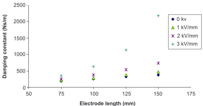
Figure 10 shows the effect of electrode length variation to the damping constant. Similar to electrode gap variation, the variation of electrode length also has higher influence on the damping constant in on-field condition. However, the influence of electrode length variation is not as severe as electrode gap variation.
In zero-field condition, the alteration of electrode length from a minimum of 75 mm to a maximum of 150 mm yields the increase in damping constant value by a factor of 2, while in a condition when 3 kVmm–1 of electric field strength is applied, the increasing is by a factor of 6. In on-field condition, the electrode length variation does not only influence the pressure drop, but also effects the yield stress of the ER fluid. The amount of ER fluid involved in chainlike structure formation increases as the electrode longthens, which in turn increases the yield stress.
5.0 CONCLUSIONS
From the mathematical model and the simulations presented, it can be concluded that the high damping level can be obtained by increasing the electric field strength, choosing an appropriate ER fluid, increasing the electrode length or decreasing the gap between the electrodes.
The ER damper filled with Al 3565 has a wider controllable range compared to units ER damper filled with TX-ER5 or ER-100 since Al 3565 produces the highest yield stress for a given electric field strength.
The variation of electrode gap and electrode length has a significant effect on the damping value of the damper. In on-field condition, the effect is even more severe
Figure 10 Effect of electrode length variation to the damping constant for various electric field strength
0 kv
Damping constant (Ns/m)
75 1000
1500 2000
500
0
50 100 125 150 175
1 kV/mm
2 kV/mm 3 kV/mm 2500
since the variation of the gap and the length of the electrode do not only influence the pressure drop, but also the yield stress of the material.
ACKNOWLEDGEMENTS
The authors would like to thank the Malaysian Ministry of Science, Technology and Environment for sponsoring this research under project IRPA 03-02-02-0016 SR0003/ 07-02.
REFERENCES
[1] Mukhlis, R. Z., N. A. N. Mohamed, and M. J. M. Nor. 2004. A Preliminary Study on Developing an Intelligent Automotive Suspension using Electrorheological Fluid. Proceeding of Engineering Materials Seminar and Exhibition 2004. Institut Teknologi Bandung Indonesia. 111-121.
[2] Len, H. G., and S. B. Choi. 2002. Dynamic Properties of an ER Fluid Under Shear and Flow Modes.
Material and Design. 23: 69-76.
[3] Makris, N., S. A. Burton, and D. P. Taylor. 1996. Electrorheological Damper with Annular Ducts for Seismic Protection Applications. Smart Materials and Structures. 5: 551-564.
[4] Hughes, W. F. 1979. An Introduction to Viscous Flow. London: McGraw-Hill Book Company. [5] Hao, T. 2002. Electrorheological Suspensions. Advances in Col loid and Interface Science.97: 1-35. [6] Kamath, G. M., M. K. Hurt, and N. M. Wereley. 1996. Analysis and Testing of Bingham Plastic Behavior
in Semi-active Electrorheological Fluid Dampers. Smart Materials and Structures. 5: 576-590.
[7] Lindler, J., and N. M. Wereley. 2003. Quasy-steady Bingham Plastic Analysis of an Electrorheological Flow Mode Bypass Damper with Piston Bleed. Smart Materials and Structures. 12: 305-317.
[8] http://www.tudresden.de/mw/ilr/lampe/DATENBAN/ERF-UEB (29 July 2005).
![Figure 1Schematic diagram of an intelligent ER suspension system [1]](https://thumb-us.123doks.com/thumbv2/123dok_us/1259988.1158586/2.595.118.500.399.558/figure-schematic-diagram-intelligent-er-suspension.webp)