Design and Analysis of Nosecone of Kaplan Turbine at High Flow
Conditions using Computational Fluid Dynamic Analysis
Kuruva Venkata Ramana1, A Vidya Sagar (Mtech)2 1
P.G. Scholar, 2Guide, Head of the Department 1,2
BRANCH. : MACHINE DESIGN 1,2
Geetanjali College of Engineering and Technology
Email id : [email protected], [email protected]
ABSTRACT
In this generation multitechnology is developing day by day. Especially in producing electric power (current) using natural resources. For every engineer, it’s very important to show enthusiastic to produce current from natural resources. Because of multitechnologies will develop by engineers only. The Kaplan turbine is an outward or inward flow reaction turbine. Here working fluid changes pressure as it moves through the turbine. Power is gained from both the Hydro static head and from the kinetic energy of flowing water. The Kaplan turbine is an outward flow reaction turbine, which means that the working fluid changes pressure as it moves through the turbine and gives up its energy. Power is recovered from both the hydrostatic head and from the kinetic energy of the flowing water. In this project, Kaplan turbine with different nose cones were studied briefly and fluid flow analyzed for Kaplan turbine with different nose cones using Ansys CFD software.
This analysis studied at high waterflow condition. From analysis results, Kaplan turbine with optimized nose cone was proposed at high waterflow condition.
CADTOOL: UNIGRAPHICS CAETOOL: ANSYSCFD
INTRODUCTION
ABOUT THE COMPONENT
A ship moves through the water through propelling devices, such as paddle wheels or propellers. These devices impart velocity to a column of water and moves it in the opposite direction in which it is desired to move the ship. A force, called reactive force because it reacts to the force of the column of water, is developed against the velocity imparting device. This force, also called thrust, is transmitted to the ship and causes the ship to move through the water.
The propeller is the propulsion device used in almost all naval ships. The thrust developed on the propeller is transmitted to the ship’s structure by the main shaft through the thrust bearing. The main shaft extends from the main reduction gear shaft to the propeller supported and held in alignment by the spring bearings, the stern tube bearings, and the strut bearing. The thrust, acting on the propulsion shaft as a result of the pushing effect of the propeller, is transmitted to the ship’s structure by the main thrust bearing. In most ships, the main thrust bearing is located at the forward end of the main shaft within the main reduction gear casing.
PRODUCTLIFECYCLEMANAGEMENT
usually in the form of a drawing. The manufacturing process starts from the design specifications and ends with shipping of the actual products.
The activities involved in the design process can be classified largely as three types: synthesis, analysis and manufacturing. The initial synthesis design activities (such as identification of the design need, formulation of design specifications, feasibility study with collecting relevant design information, and design conceptualization) are part of the synthesis sub process. That is, the result of the synthesis subprocess is a conceptual design of the prospective product in the form of a sketch or a lay outdrawing that shows the relationships among the various product components. The major financial commitments needed to realize the product idea are made and the functionality of the product is determined during this phase of the cycle. Most of the information generated and handled in the synthesis sub process is qualitative and consequently is hard to capture in a computer system. Once the conceptual design has been developed, the analysis subprocess begins with Analysis and optimization of the design. An analysis model is derived first because the Analysis subprocess is applied to the model rather than the design itself. Despite the rapid growth in the power and availability of computers in engineering, the abstraction of analysis models will still be with us for the foreseeable future. The analysis model is obtained by removing from the, design unnecessary details, reducing dimensions, and recognizing and employing symmetry. Dimensional reduction, for example, implies that a thin sheet of material is represented by an equivalent surface with a thickness attribute or that along slender region is represented by a line having cross-sectional properties. Bodies with symmetries in their geometry and loading are usually analyzed by considering a portion of the model.
FINITE ELEMENT METHOD
The FEM is numerical analysis technique for obtaining approximate solutions to wide variety of engineering problems. The method originated in the aerospace industry as a tool to study stresses in complicated airframe structures. It grew out of what was called the matrix analysis method used in aircraft design. The method has gained popularity among both researchers and practitioners and after so many developments codes are developed for wide variety of problems.
Major steps involved in any finite element software
1.Preprocess
Create geometrical model by either hyper mesh or ansys software or any cad software.
Import a cad model in hyper mesh/ansys software if geometrical model was done by cad software. Select analysis type such as static,
modal, transient dynamic, thermal analysis.
Insert element type either 2-Dimensional (ex: Trusses, Beams) or 3-Dimensional (ex:Solid, Shell, Plate) Apply material properties (Young's
modulus, Poisson ratio, Thermal conductivity,
Density values)based on types of materials.
Apply meshing to FE model.
Also apply boundary conditions and Loading conditions.
2.Solution
Get nodal solutions such as displacement values at each node or temperature value sat each node by solving linear or nonlinear algebraic equations at each node.
These solutions formed based on matrix formulation for system of equations. That Formula noted as
3.Postprocessing
Postprocessor software contains sophisticated routines used for sorting, printing, and plotting selected results from a finite element solution. Element Characteristic Shape:
In general, four shapes are possible: Point, Line, Area or Volume. A point element Typically dented by a node, e.g., a mass element. A line element is typically represented by a line or arc connecting two or three nodes. E.g., beams spars, pipes and axi symmetric shells. An area element has a triangular or quadrilateral shape and may be a 2-D solidelementor shell element. A volume element has a tetrahedral or brick shape usually a 3-D solid element Degrees of Freedom and Discipline:
The DOF of the element determine the discipline for which the element is applicable:
sufficient to characterize the model’s response. Including the Unnecessary DOF increases the solution memory requirements and runtime
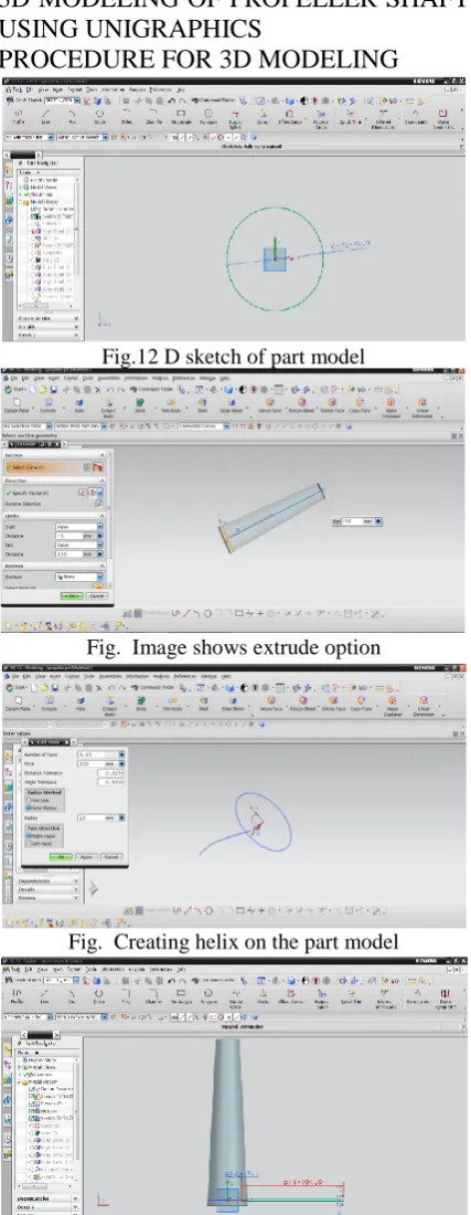
3D MODELING OF PROPELLER SHAFT USING UNIGRAPHICS
PROCEDURE FOR 3D MODELING
Fig.12 D sketch of part model
Fig. Image shows extrude option
Fig. Creating helix on the part model
Fig. Image shows 2 D sketch of blade on part model
Fig. Creating swept curve
Fig Creating edge blend on inner side at outer edge
Fig Creating edge blend on inner side at inner edge
Fig Creating edge blend on outerside at top edge
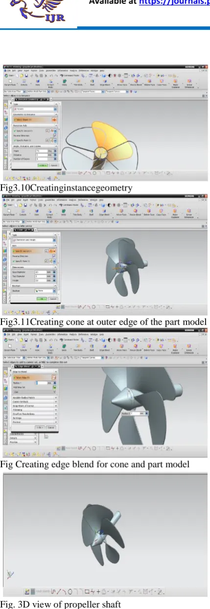
Fig3.10Creatinginstancegeometry
Fig3.11Creating cone at outer edge of the part model
Fig Creating edge blend for cone and part model
Fig. 3D view of propeller shaft
FLUIDDYNAMICANALYSISOFPROPEL LERSHAFT
4.1CALCULATIONOFFLOW
VELOCITYTHROUGHPROPELLER SHAFT
Thrust power acting on propeller(P)=800KW
Thrust for ceacting at propeller(Ft)=45KN Wek now thrust power(P)=Ft*Vf
Flow velocity(Vf)=800000/45000=17.77m/s 4.2MESHING
Before meshing the model and even before building the model, it is important to think about whether a free mesh or a mapped mesh is appropriate for the analysis. A free mesh has no restrictions in terms of element shapes and has no specified pattern applied to it.
Compare to a free mesh, a mapped mesh is restricted interms of the element shape it contains and the pattern of the mesh. A mapped are a mesh contains either quadrilateral or only triangular elements, while a mapped volume mesh contains only hexa hedron elements. If we want this type of mesh, we must build the geometry as series of fairly regular volumes and/or areas that can accept a mapped mesh.
4.3COMPUTATIONAL FLUID DYNAMICS(CFD)
ANSYS provides a comprehensive suite of computational fluid dynamic software for modeling fluid flow and other related physical phenomena. It offers unparallel led fluid flow analysis capabilities, providing all the tools needed to design and optimize new fluids equipment and to trouble shoot existing installations. The primary ANSYS products in the fluids area are ANSYS Fluent and ANSYSCFX. With these solutions you can simulate a wide range of phenomena: aerodynamics, combustion, hydrodynamics, mixtures of liquids/ solids/ gas, particle dispersions, reacting flows, heat transfer, and much more. Steady-state and transient flow phenomena are easily and quickly solved.
combustion, and other parameters evolve with time. Fluid dynamics is the study of the movement of fluids, including their interactions as two fluids come into contact with each other. In this context, the term "fluid" refers to either liquid or gases. It is a macroscopic, statistical approach to analyzing these interactions at a largescale, viewing the fluids as a continuum of matter and generally ignoring the fact that the liquid or gas is composed of individual atoms. Fluid dynamics is one of the two main branches of fluid mechanics, with the other branch being fluid statics, the study of fluids at rest.(Perhaps not surprisingly, fluid statics may be thought of as a bit less exciting most of the time than fluid dynamics.)
Key Concepts of Fluid Dynamics
Every discipline involves concepts that are crucial to understanding how it operates. Here are some of the main ones that you'll come across when trying to understand fluid dynamics.
Basic Fluid Principles
The fluid concepts that apply in fluid statics also come into play when studying fluid that is in motion. Pretty much the earliest concept in fluid mechanics is that of buoyancy, discovered in ancient Greece by Archimedes. As fluids flow, the density and pressure of the fluids are also crucial to understanding how they will interact. The viscosity determine show resistant the liquid is to change, so is also essential in studying the movement of the liquid.
Here are some of the variables that come up in these analyses:
Bulk viscosity: μ Density: ρ
Kinematic viscosity: ν = μ / ρ
Flow
Since fluid dynamics involves the study of the motion of fluid, one of the first concepts
that must be understood is how physicists quantify that movement. The term that physicists use to describe the physical properties of the movement of liquid is flow. Flow describes a wide range of fluid movement, such blowing through the air, flowing through a pipe, or running along a surface. The flow of a fluid is classified in a variety of different ways, based upon the various properties of the flow.
Steady vs. Unsteady Flow
If the movement of a fluid does not change overtime, it is considered a steady flow. This is determined by a situation where all properties of the flow remain constant with respect to time, or alternately can be talked about by saying that the time-derivatives of the flow field vanish. (Check out calculus for more about understanding derivatives.) A steady state flow –is even less time-dependent, because all of the fluid properties (not just the flow properties) remain constant at every point within the fluid. So if you had a steady flow, but the properties of the fluid itself changed at some point(possibly because of a barrier causing time-dependent ripples in some parts of the fluid),then you would have a steady flow that is not a state flow. All steady-state flows are examples of steady flows, though. A current flow in gat a constant rate through a straight pipe would be an example of a steady-state flow (and also a steady flow). If the flow itself has properties that change over time, then it is called an unsteady flow or a transient flow. Rain flowing into a gutter during as to rm is an example of an unsteady flow.
Laminar flow vs. Turbulent flow
A smooth flow of liquid is said to have a laminar flow. Flow that contains seemingly chaotic, non-linear motion are said to have a turbulent flow. By definition, a turbulent flow is a type of unsteady flow. Both types of flows may contain eddies, vortices, and various types of recirculation, though the more of such behaviors that exist the more likely the flow is to be classified as turbulent.
The distinction between whether a flow is laminar or turbulent is usually related to the Reynolds number (Re). The Reynolds number was first calculated in 1951 by physicist George Gabriel Stokes, but it is named after the 19th century scientist Osborne Reynolds.
The Reynolds number is dependent not only on the specifics of the fluid itself but also on the conditions of its flow, derived as the ratio of inertial forces to viscous forces in the following way:
Re = Inertial force / Viscous forces Re = (ρ V dV/dx) / (μ d2
V/dx )
The term dV/dx is the gradient of the velocity (or first derivative of the velocity), which is proportional to the velocity (V) divided by L, representing a scale of length, resulting in dV/dx = V/L. The second derivative is such that d 2V/dx = V2/L . Substituting these in for the first and second derivatives results in:
Re = (ρV V/L) / (μ V/L2 ) Re = (ρV L) / μ
You can also divide through by the length scale L, resulting in a Reynolds number per foot, designated as Ref = V/ν.
A low Reynolds number indicates smooth, laminar flow. A high Reynolds number indicates a flow that is going to demonstrate eddies and vortices, and will generally be more turbulent.
Pipe flow vs. Open-channel Flow
Pipe flow represents a flow that is in contact with rigid boundaries on all sides, such as
water moving through a pipe (hence the name "pipe flow") or air moving through
an air duct.
Open-channel flow describes flow in other situations where there is at least one free surface that is not in contact with a rigid boundary. (In technical terms, the free surface has 0 parallel sheer stress.) Cases of open-channel flow include water moving through a river, floods, water flowing during rain, tidal currents, and irrigation canals. In these cases, the surface of the flowing water, where the water is in contact with the air, represents the "free surface" of the flow.
Flows in a pipe are driven by either pressure or gravity, but flows in open-channel situations are driven solely by gravity. City water systems often use water towers to take advantage of this, so that the elevation difference of the water in the tower (the hydrodynamic head) creates a pressure differential, which are then adjusted with mechanical pumps to get water to the locations in the system where they are needed.
Compressible vs. Incompressible
Gases are generally treated as compressible fluids, because the volume that contains them can be reduced. An air duct can be reduced by half the size and still carry the same amount of gas at the same rate. Even as the gas flows through the air duct, some regions will have higher densities than other regions.
As a general rule, being incompressible means that the density of any region of the fluid does not change as a function of time as it moves through the flow. Liquids can also be compressed, of course, but there's more of a limitation on the amount of compression that can be made. For this reason, liquids are typically modeled as if they were incompressible.
Bernoulli's Principle
Simply put, it relates the increase of speed in a liquid to a decrease in pressure or Potential energy.
For incompressible fluids, this can be described using what is known as Bernoulli's equation:
Where 'g' is the acceleration due to gravity, 'ρ' is the pressure throughout the liquid, 'v' is The fluid flow speed at a given point, 'z' is the elevation at that point, and 'p' is the Pressure at that point. Because this is constant within a fluid, this means that these Equations can relate any two points,1and2,with the following equation:
The relationship between pressure and potential energy of a liquid based on elevation is also related through Pascal's Law.
Applications of Fluid Dynamics
Two-thirds of the Earth's surface is water and the planet is surrounded by layers of atmosphere, so we are literally surrounded at all times by fluids ... almost always in motion. Thinking about it for a bit, this makes it pretty obvious that there would be a lot of interactions of moving fluids for us to study and understand scientifically. That's where fluid dynamics comes in, of course, so there's no shortage of fields that apply concepts from fluid dynamics.
This list is not at all exhaustive, but provides a good overview of ways in which fluid dynamics show up in the study of physics across a range of specializations:
METHODOLOGY USED IN THE PROJECT:
Develop a 3D model from the available 2D drawings of the given component. The 3D model is created using UNIGRAPHICS-NX software.
The 3D model is converted into parasolid file (.xt) and imported into Ansys CFD for generating mesh and apply boundary conditions.
Calculate pressure and deflections of the original model and check if the component is withstanding for the operating speed in CFD software.
ELEMENT TYPE USED Element Type : Solid 187
Element Shape : 2D shape- R-Trios ( right angle trio) AND 3D shape- Tetrahedral
Number of nodes : 8
Number of DOF=3(Ux, Uy, Uz)
SOLID187 is used for the three-dimensional modeling of solid structures. The element is defined by eight nodes having three degrees of freedom at each node: translations in the nodal x, y, and z directions. The element has plasticity, stress stiffening, large deflection, and large strain capabilities.
Below image show structural solid 187
MATERIAL PROPERTIES
A material's property (or materials Property)is an intensive, often quantitative, property of some material. The Material used for missile piston is Al6061alloy. The composition of the material is as follows
Typical properties of Aluminium alloy 6061 include
• Medium to high strength • Good toughness
• Good surface finish
• Excellent corrosion resistance to atmospheric conditions
• Good corrosion resistance to seawater
• Can be anodized
• Good weldability and brazability • Good workability
• Widely available
Physical Properties of Aluminium 6061 alloy
Density : 2.7g/cm3
Melting Point : Approx580°C Modulus of Elasticity : 70-80GPa Poisson’s Ratio : 0.33
Yield strength : 180Mpa
LOADING CONDITIONS
Calculated velocity value is given as input to Propeller shaft turbine and observed pressure values in CFD software.
PROCEDURE FOR COMPUTATIONAL FLUID DYNAMIC ANALYSIS OF PROPELLER SHAFT:-
K-EPSILAN RULE
The k – ε model was invented first by Jones and Launder . It is now consider the standard turbulence model for engineering simulation of flows.
turbulent kinetic energy. The mixing length model lacks this kind of generality. The words, the ratio between Reynolds stress and mean rate of deformations is the same in all directions.
turbulence.
Also eddy viscosity is inversely proportional to rate of dissipation.
Finite Element Modeling:
3D model of the propeller shaft was developed in UNIGRAPHICS from the 2d drawings provided. The model was then converted into a parasolid model to import into CFD. A Finite Element model was developed with solid 187 elements. In these models, the solid elements are used because of the thin wall of the component.
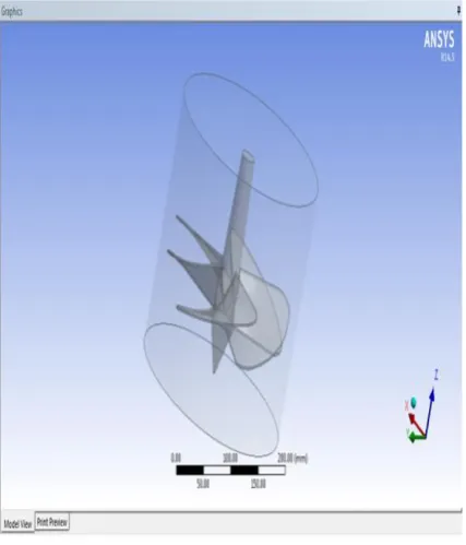
Fig Imported Propeller and enclosure in ANSYSCFD
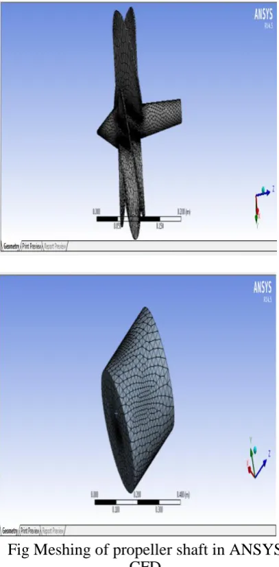
Fig Meshing of propeller shaft in ANSYS CFD
Fig shows in let of propeller shaft
Fig. shows outlet of propeller shaft Boundary conditions
Calculated inlet flow velocity applied at inlet region of propeller.
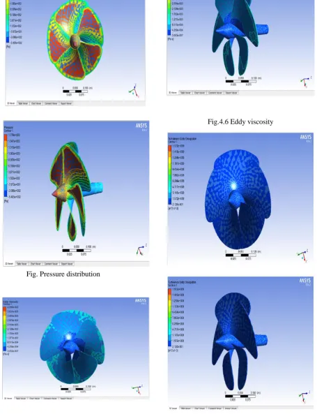
Fig. Stream velocity distribution
Fig. Pressure distribution
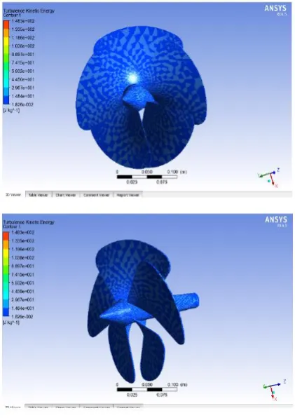
Fig. Turbulence eddy dissipation CONCLUSION
From CFD analys is results max. fluid pressure formed on propeller shaft is 62890 PA and yield strength of aluminium is 300 MPA. So fluid pressures are formed less than yield strength of aluminium , so designed propeller shaft is in safe condition at flow velocity.
REFERENCES
[1]IMO.Annex5,Resolution MEPC.245(66),2014 Guidelines on the method of calculation of the
attained Energy Efficiency Design Index
(EEDI)for new ships.
http://www.imo.org/KnowledgeCentre/IndexofIM OResolutions/MEPC%20Resolutions/
MEPC%20245%2066.pdf, Marine Environment Protection Committee, 2014
[2]IMO. Annex 9, Resolution MEPC. 213 (63), 2012 Guidelines for the development of a Ship Energy Efficiency Management Plan (SEEMP).
http://www.imo.org/KnowledgeCentre/IndexofIM OResolutions/Documents/MEPC%20-%20
Marine% 20 Environment %20 Protection /213 (63) .pdf, Marine Environment Protection
Committee, 2012.
[3] IMO. MEPC 59/4/15, Prevention of air pollution from ships, Energy
Efficiency Operational Indicator (EEOI)
http://www.rina.org.uk/hres/mepc%2059 4
16.pdf, Marine Environment Protection
Committee, 2009.