Small Platform System Manual
NEC America, Inc. has prepared this document for use by its em-ployees and customers. The information contained herein is the property of NEC America, Inc. and shall not be reproduced without prior written approval from NEC America, Inc.
NEAX and Dterm are registered trademarks of NEC Corporation.
Copyright 1998 NEC America, Inc.
NEAX2000 IVS
Small Platform System Manual
TABLE OF CONTENTS
Page
LIST OF FIGURES... iv
LIST OF TABLES... vi
REGULATORY INFORMATION ... vii
1. Regulatory Requirements ... vii
2. FCC Part 15 Requirements... vii
3. FCC Part 68 Registration... vii
3.1 Company Notification... vii
3.2 Service Requirements... viii
3.3 Location of FCC Compliance Labels ... viii
4. Direct-Inward Dialing (DID) Calls ... viii
5. Regulatory Information on Single-Line Analog Telephones... ix
6. Hearing Aid Compatibility... ix
7. Industry Canada CS-03 ... ix
8. Safety Certifications ... x
8.1 Safety Considerations... x
CHAPTER 1 INTRODUCTION ... 1
1. PURPOSE ... 1
2. REFERENCE MANUAL ... 1
3. HOW TO FOLLOW THIS MANUAL... 2
4. SCOPE OF INSTALLATION PROCEDURES ... 2
CHAPTER 2 GENERAL INFORMATION ... 3
1. TRUNKING DIAGRAM ... 3
2. SYSTEM CONFIGURATIONS... 5
3. FUNCTIONAL OUTLINE OF EQUIPMENT ... 9
3.1 Functional Outline of Modules ... 9
3.2 Functional Outline of Installation Hardware ... 10
3.3 Functional Outline of Circuit Cards ... 10
3.3.1 Control Circuit Card ... 10
3.3.2 Application Circuit Cards... 11
3.3.3 Line/Trunk Circuit Cards ... 12
1. PRECAUTIONS ... 19
1.1 Grounding Requirements... 19
1.2 Static Electricity Guard... 20
1.3 Removing/Inserting Circuit Cards ... 22
2. PROCEDURE ... 24
NAP-200 -001 Unpacking ... 26
1. Unpacking Procedure... 26
-002 Marking and Drilling... 28
1. Confirmation of the Equipment Layout ... 28
2. Marking... 28
2.1 Floor Standing ... 28
2.2 Wall-Mounting ... 29
3. Drilling ... 30
-003 Installation of Main Equipment ... 31
1. Floor Standing Installation... 31
2. Wall-Mounting Installation ... 34
3. 19-Inch Rack-Mounting Installation ... 39
4. Desk Top Installation... 41
5. AC Power Cabling ... 43
6. MDFM/BATTM Installation ... 48
-004 Connection of Battery... 52
1. Battery Connection... 52
1.1 Internal Battery Connection... 54
1.2 Battery Connection in the BATTM... 56
-005 Cable Running to the MDF... 57
1. MDF Cable ... 57
2. Installation of External MDF ... 58
3. Cable Running to the External MDF... 59
4. Cable Running to the MDFM ... 60
-006 Termination of Cables on the MDF ... 62
1. Cable Connection to the MDF ... 62
2. MDF Cross Connections ... 66
-007 Installation of SN716 DESKCON ... 116
1. SN716 - DESKCON ... 116
-008 Switch Setting of Circuit Card... 127
1. Circuit Cards Switch Setting... 127
2. PN-CP03 (MP) ... 128
3. PZ-PW86 (PWR) ... 131
4. PZ-PW86(D) (PWR) ... 134
5. PN-PW00 (EXTPWR)... 136
6. PN-8DLCJ/8dlcp (DLC) ... 138
7. PN-8LCS (LC) ... 139
-009 Mounting of Circuit Cards... 140
1. Mounting Procedure ... 140
2.1 CAT ... 144
2.2 MAT... 145
2.3 Feature Programming ... 145
-011 Operation Test... 150
1. Operation Test... 150
-012 Cleaning and Visual Check ... 151
1. Cleaning ... .... 151
2. Visual Check ... 151
-013 Mounting of the Front Cover... 152
1. Mounting of the Front Cover... 152
CHAPTER 4 OFFICE DATA PROGRAMMING... 153
1. CUSTOMIZING DATA ... 153
1.1 Data Programming Procedure ... 153
1.2 General Information on Customizing Data... 153
1.2.1 Numbering Plan ... 153
1.2.2 Station Data ... 154
1.2.3 Trunk Data ... 154
1.2.4 Station Hunting Group Data ... 155
1.2.5 Call Pickup Group Data ... 155
1.2.6 Speed Calling-System Data ... 156
1.2.7 Port Assignment Table... 156
1.3 Customer Specification Sheets... 161
1.3.1 Numbering Plan ... 161
1.3.2 Station Data ... 162
1.3.3 Trunk Data ... 163
1.3.4 Station Hunting Group Data ... 164
1.3.5 Call Pickup Group Data ... 165
1.3.6 Speed Calling-System Data ... 166
1.4 System Configuration... 167
1.4.1 Port Assignment Table... 167
1.4.2 Bay Face Layout for Module ... 168
1-2 Scope of Installation Procedures ... 2
2-1 PBX Trunking Diagram ... 3
2-2 Floor Standing Installation ... 5
2-3 Wall-Mounting Installation... 6
2-4 19-Inch Rack-Mounting Installation ... 7
2-5 Desk Top Installation ... 8
2-6 Circuit Card Mounting Slots ... 16
3-1 Static Electricity Guard ... 20
3-2 Procedure Flowchart... 24
001-1 Unpacking of Main Equipment... 27
002-1 Floor Marking for Main Equipment... 28
002-2 Wall Mounting Points ... 29
002-3 Instruction for Anchor Bolt ... 30
003-1 Securing of the BASE ... 31
003-2 Mounting of the PIM... 32
003-3 Mounting of the TOP COVER ... 33
003-4 Screwing the RACK PARTS to a Wall ... 35
003-5 Mounting the PIM to the RACK PARTS... 36
003-6 Screwing the PIM to the RACK PARTS... 37
003-7 Connecting the Covers and AC CORD to the PIM ... 38
003-8 Connecting the Covers and AC CORD to the PIM ... 39
003-9 Mounting the PIM to the 19-Inch Rack ... 40
003-10 Connecting the Covers and AC CORD to the PIM ... 41
003-11 Connecting the RUBBER FOOT to the PIM ... 42
003-12 Cable Connection on the PZ-PW86... 43
003-13 Cable Connection between the PZ-PW86 and the BWB ... 45
003-14 AC Power Cable Wiring ... 46
003-15 Screwing the AC CORD-B to the Terminals ... 47
003-16 Connection of RACK PARTS and BASE ... 48
003-17 Connection of RACK PARTS... 49
003-18 Connection of the PIM and the RACK PARTS ... 50
003-19 Connection of PIM and MDFM/BATTM ... 51
004-1 Internal Battery Mounting... 54
004-2 Internal Battery Connection ... 55
004-3 Battery Mounting into the BATTM... 56
005-1 MDF Cable... 57
005-2 Cable Hole Location ... 58
005-3 Cable Running to External MDF ... 59
005-4 Cable Running to MDFM ... 60
005-5 MDF Cable Connection to MDFM Example... 61
006-1 Card Slots and LTC Connectors Location (PIM0) ... 62
006-2 Card Slots and LTC Connectors Location (PIM1) ... 63
006-3 Location of Each LEN ... 64
006-4 LTC Connector Pin Arrangement (PIM0)... 65
006-5 LTC Connector Pin Arrangement (PIM1)... 70
006-11 MDF Cross Connection for a Single Line Telephone (Standard Line)... 82
006-12 MDF Cross Connection for a Single Line Telephone (Long Line) ... 83
006-13 MDF Cross Connection for a Multiline Terminal/DSS Console (Standard Line)... 84
006-14 MDF Cross Connection for a Multiline Terminal/DSS Console (Long Line) ... 85
006-15 Mounting Handset Support to SN610 ATTCON ... 86
006-16 Jack Set Installation for SN610 ATTCON ... 87
006-17 SN610 ATTCON Switch Setting ... 88
006-18 Cable Connection to SN610 ATTCON ... 90
006-19 MDF Cross Connection for SN610 ATTCON ... 91
006-20 MDF Cross Connection for Day/Night Mode Change by External Key... 92
006-21 External TAS Indicator Connection Outline ... 93
006-22 MDF Cross Connection for a TAS Indicator with a Battery... 94
006-23 MDF Cross Connection for a TAS Indicator with a Battery (Ground Start)... 95
006-24 Paging Equipment Connection Outline ... 96
006-25 MDF Cross Connection for Paging Equipment ... 97
006-26 External Tone Source Connection Outline ... 100
006-27 MDF Cross Connection for an External Tone Source Equipment ... 101
006-28 Connecting a Tone Source Supplied with D.C. ... 103
006-29 MDF Cross Connection for External BGM Sources... 104
006-30 Cable Connection Between PN-TNTA and External BGM Sources ... 105
006-31 PFT Connection Outline ... 106
006-32 MDF Cross Connection for the PFT (PN-AUCA) ... 107
006-33 PFT (PZ-8PFTA) Connection Outline ... ... 109
006-34 Connection of 25-Pair Cable and PZ-8PFTA... 110
006-35 Mounting PZ-8PFTA Card to the PIM ... 111
006-36 PFT Connector Pin Assignment ... 112
006-37 MDF Cross Connection for the PFT (PZ-8PFTA) ... 113
006-38 MDF Cross Connection for an Alarm Display Panel ... 115
007-1 Assembly of SN716 DESKCON ... 116
007-2 SN716 DESKCON Cable Connection ... 117
007-3 MDF Cross Connection With AC Adapter Power Option ... 118
007-4 MDF Cross Connection via PN-PW00 Power Option ... 119
007-5 Mounting of Handset Support to SN716 DESKCON ... 120
007-6 Headset Installation for SN716 DESKCON ... 121
007-7 Cable Connection to SN716 DESKCON ... 122
007-8 AC-DC ADAPTER Connection to SN716 DESKCON ... 123
007-9 Mounting PW00 Card into PIM ... 124
007-10 PW00 Card Connection to SN716 DESKCON ... 125
007-11 MDF Cross Connection for SN716 DESKCON ... 126
008-1 PN-CP03 (MP) Card ... 128
008-2 PZ-PW86 (PWR) Card... 131
008-3 PZ-PW86(D) (PWR) Card... 134
008-4 PN-PW00 (EXTPWR) Card ... 136
008-5 PN-8DLCJ/8DLCP (DLC) Card... 138
008-6 PN-8LCS (LC) Card ... 139
2-2 Functional Outline of Modules ... 9
2-3 Functional Outline of Installation Hardware ... 10
2-4 Functional Outline of Control Circuit Cards ... 10
2-5 Functional Outline of Application Circuit Cards ... 11
2-6 Functional Outline of Line/Trunk Circuit Cards ... 12
2-7 Line Condition of Each Terminals... 14
3-1 Removing/Inserting Circuit Cards Procedure ... 22
003-1 Recommended Fasteners ... 34
006-1 LTC Connector Accommodation... 62
006-2 LTC Connector Accommodation... 63
006-3 LTC0-LTC2 MDF Cross Connection Information... 66
006-4 LTC0-LTC2 MDF Cross Connection Information... 71
008-1 Control Circuit Cards ... 127
008-2 Line/Trunk Circuit Cards ... 127
008-3 PN-CP03 (MP) Card Lamp Indications ... 128
008-4 PN-CP03 (MP) Card Switch Settings ... 129
008-5 PZ-PW86(C) (PWR) Card Lamp Indications ... 132
008-6 PZ-PW86(C) (PWR) Card Switch Settings ... 133
008-7 PZ-PW86(D) (PWR) Card Lamp Indications ... 134
008-8 PZ-PW86(D) (PWR) Card Switch Settings ... 135
008-9 PN-PW00 (EXTPWR) Card Lamp Indications ... 136
008-10 PN-PW00 (EXTPWR) Card Switch Settings... 137
008-11 PN-8DLCJ8DLCP (DLC) Card Lamp Indications ... 138
008-12 PN-8LCS (LC) Card Lamp Indications... ... 139
4-1 Data Programming Procedure ... 153
4-2 Port Assignment Method ... 156
4-3 Numbering Plan Data Table ... 161
4-4 Station Data Table ... 162
4-5 Trunk Data Table ... 163
4-6 Station Hunting Group Data Table... 164
4-7 Call Pickup Group Data Table ... 165
4-8 Speed Calling-System Data Table... 166
4-9 Port Assignment Table ... 167
4-10 Quantity Table for Module ... 168
4-11 Quantity Table for Line/Trunk Circuit Cards ... 169
4-12 Quantity Table for Control Circuit Cards ... 169
The Federal Communications Commission (FCC) has established rules that permit the NEAX2000 IVS to be direct-ly connected to the telephone network. A jack is provided on party lines or coin lines.
The telephone company may make changes in its technical operations and procedures. If such changes affect the compatibility or use of the NEAX2000 IVS, the telephone company must provide adequate notice of the changes.
This equipment complies with the requirements in Part 15 of FCC Rules for a Class A computing device. Operation of this equipment in a residential area may cause unacceptable interference to radio and TV reception requiring the operator to take whatever steps are necessary to correct this interference.
2. FCC Part 15 Requirements
In compliance with FCC Part 15 Rules, the following statement is provided:
3. FCC Part 68 Registration
3.1 Company Notification
Before installing the NEAX2000 IVS to the telephone network, the telephone company must be provided with the following:
• Your telephone number
• The FCC registration numbers:
JAPAN USA
PBX AY5JPN-20542-PF-E AY5USA-21582-PF-E
Hybrid AY5JPN-20543-MF-E AY5USA-21583-MF-E
Key system AY5JPN-20586-KF-E AY5USA-21584-KF-E
WARNING
In the event of equipment malfunction, all repairs will be performed by NEC or an authorized distributor of NEC. It is the responsibility of users requiring service to report the need for service to NEC or to one of their authorized distributors.
If the equipment causes harm to the telephone network, the telephone company will notify you in advance that tem-porary discontinuance of service may be required. If advance notice is not practical, the telephone company will no-tify the customer as soon as possible. Also, you will be advised of your right to file a complaint with the FCC if you believe it is necessary.
The telephone company may make changes in its facilities, equipment, operations, or procedures that affect the op-eration of the equipment. If this happens, the telephone company will provide advance notice in order for you to make necessary modifications in order to maintain uninterrupted service.
If trouble is experienced with this equipment, please contact NEC America, Inc.’s Oregon plant at (503) 648-5000 for repair and/or warranty information. If the trouble is causing harm to the telephone network, the telephone com-pany may request that you remove the equipment from the network until the problem is resolved.
NO REPAIRS CAN BE DONE BY THE CUSTOMER.
3.3 Location of FCC Compliance Labels
Labels stating the NEAX2000 IVS FCC registration number and compliance with FCC Parts 15 and 68 are attached to the Base Unit. If the unit is in a table-top configuration, the labels are located on the side of the enclosure. Example of the labels are as follows:
4. Direct-Inward Dialing (DID) Calls
Allowing this equipment to be operated in such a manner as to not provide for proper answer supervision is a viola-tion of Part 68 of the FCC’s rules.
PROPER ANSWER SUPERVISION IS WHEN:
(a) This equipment returns answer supervision to the PSTN when DID calls are: • Answered by the called station
• Answered by the attendant
“This equipment complies with the requirements in Part 15 of FCC Rules for a Class A computing device. Operation of this equipment in a residential area may cause unacceptable interference to radio and TV re-ception requiring the operator to take whatever steps are necessary to correct the interference.”
NEAX2000 IVS
Complies With Part 68 FCC Rules
FCC Registration Numbers : AY5USA-21582-PF-E AY5USA-21583-MF-E AY5USA-21584-KF-E Ringer Equivalence : 1.6B
• A busy tone is received • A reorder tone is received.
EQUAL ACCESS REQUIREMENTS
This equipment is capable of providing users access to interstate providers of operator services through the use of access codes. Modification of this equipment by call aggregators to block access dialing codes is a violation of the TElephone Operator Consumers Act of 1990.
5. Regulatory Information on Single-Line Analog Telephones
NEC single-line telephones comply with Part 68 of FCC Rules. On the bottom of the equipment is a label that states, among other information, the FCC registration number and ringer equivalence number (REN) for the equipment. If requested, this information should be provided to the telephone company.
The equipment uses the following USOC jacks: RJ11C.
The equipment should be used only behind a PBX or KTS. The REN is used to determine the quality of device that may be connected to the telephone line. Excessive RENs on the telephone line may result in the devices not ringing in response to an incoming call. In most, but not all, areas, the sum of RENs should not exceed five (5.0). To be certain of the number of devices that may be connected to the line as determined by the total RENs, contact the tele-phone company to determine the maximum REN for the calling area.
6. Hearing Aid Compatibility
The Dterm terminals provided for the NEAX2000 IVS are hearing aid compatible. FCC rules prohibit the use of non-hearing aid compatible telephones.
NEC-type single-line telephone sets used in conjunction with the NEAX2000 IVS are hearing aid compatible. If other than NEC-type single-line telephone sets are to be used with this system, ensure that these are hearing aid com-patible.
7. Industry Canada CS-03 Certification number: 140 5976A
Load Number of the equipment: 21
NOTICE: The Industry Canada label identifies certified equipment. The certification means that the equipment meets certain telecommunications network protective operational and safety requirements. The department does not guarantee the equipment will operate to the user’s satisfaction.
Users should ensure for their own protection that the electrical ground connections of the power utility, telephone lines, and internal metallic water pipe system, if present, are connected together. This protection may be particularly important in rural areas.
CAUTION: Users should not attempt to make such connections themselves, but should contact the appropri-ate electric inspection authority, or electrician, as appropriappropri-ate.
CAUTION: The act of monitoring or recording telephone conversations under certain circumstances may vi-olate federal or state statutes. Consultation with your legal counsel prior to engaging in such prac-tices would be advisable.
NOTICE: The Load Number assigned to each terminal device denotes the percentage of the total load to be connect-ed to a telephone loop which is usconnect-ed by the device, to prevent overloading. The termination on a loop may consist of any combination of devices subject only to the requirement that the total of the load numbers of all the devices does not exceed 100.
8. Safety Certifications
This equipment has been listed by Underwriters Laboratories and found to comply with all the applicable require-ments of the standard for telephone equipment U.L. 1459. This equipment complies with CSA standard C 22.2 No. 225.
8.1 Safety Considerations
When using your telephone equipment, basic safety precautions should always be followed to reduce the risk of fire, electric shock and injury, including the following:
(1) Never install telephone wiring during a lightning storm.
(2) Never install telephone jacks in wet locations unless the jack is specifically designed for wet locations.
(3) Never touch uninsulated telephone wires or terminals unless the telephone line has been disconnected at the network interface.
(4) Use caution when installing or modifying telephone lines.
(5) Read and understand all instructions.
(6) Follow all warnings and instructions marked on the product.
(7) Unplug this product from the wall outlet before cleaning. Do not use liquid cleaners or aerosol cleaners. Use a damp cloth for cleaning.
ventilation is provided.
(11) This product should be operated only from the type of power source indicated on the marking label. If you are not sure of the type of power source available, consult with your local power company.
(12) This product normally connected with a three wire grounding type plug, a plug having a third (grounding) pin. This plug will only fit into a grounding type power outlet. This is a safety feature. If you are unable to insert the plug into the outlet, contact an electrician to replace your obsolete outlet. Do not defeat the safety purpose of the grounding type plug.
(13) Do not allow anything to rest on the power cord. Do not locate this product where the cord will be abused by persons walking on it.
(14) Do not overload wall outlets and extension cords as this can result in the risk of fire or electric shock.
(15) Never push objects of any kind into this product through cabinet slots as they may touch dangerous voltage points or short out parts that could result in a risk of fire or electric shock. Never spill liquid of any kind on the product.
(16) To reduce the risk of electric shock, do not disassemble this product, but take it to a qualified serviceman when some service or repair work is required. Opening or removing covers may expose you to dangerous voltages or other risks. Incorrect reassembly can cause electric shock when the appliance is subsequently used.
(17) Unplug this product from the wall outlet and refer servicing to qualified service personnel under the fol-lowing conditions:
(a) When the power supply cord or plug is damaged or frayed.
(b) If liquid has been spilled into the product.
(c) If the product has been exposed to rain or water.
(d) If the product does not operate normally by following the operating instructions. Adjust only those controls, that are covered by the operating instructions because improper adjustment of other controls may result in damage and will often require extensive work by a qualified technician to restore the product to normal operation.
(e) If the product has been dropped or the cabinet has been damaged.
(f) If the product exhibits a distinct change in performance.
(18) Avoid using a telephone (other than a cordless type) during an electrical storm. There may be a remote risk of electric shock from lightning.
This manual explains the installation procedure for the NEAX2000 IVS (PBX) Small Platform System.
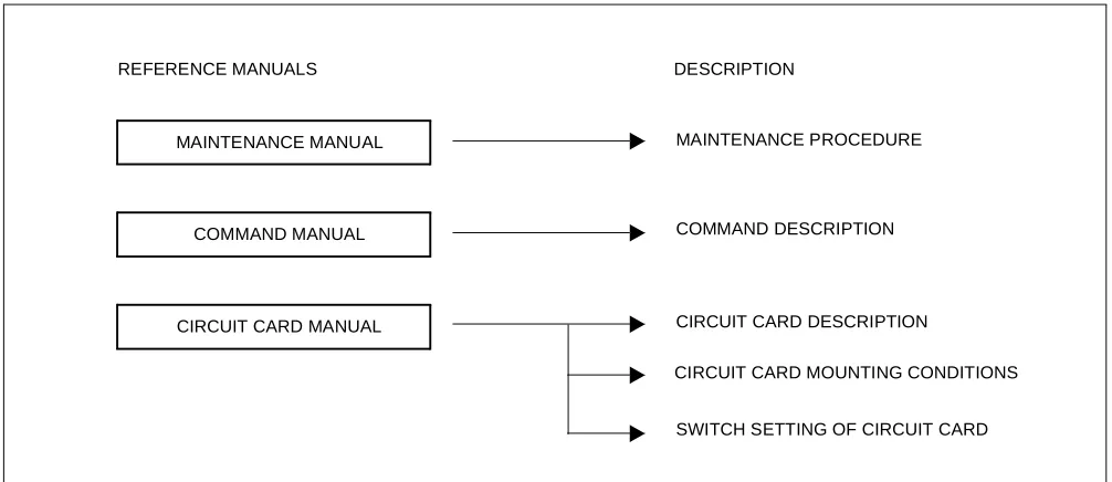
2. REFERENCE MANUAL
During installation, refer also to the NEAX2000 IVS manuals below:
Figure 1-1 Reference Manuals for Installation
CIRCUIT CARD MANUAL
COMMAND DESCRIPTION MAINTENANCE PROCEDURE MAINTENANCE MANUAL
REFERENCE MANUALS
COMMAND MANUAL
CIRCUIT CARD DESCRIPTION
CIRCUIT CARD MOUNTING CONDITIONS
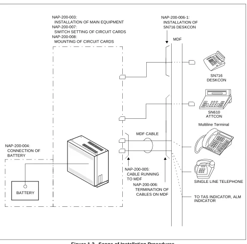
4. SCOPE OF INSTALLATION PROCEDURES This manual covers the installation shown in Figure 1-2.
Figure 1-2 Scope of Installation Procedures
MDF
MDF CABLE
SN610 ATTCON
Multiline Terminal NAP-200-003:
INSTALLATION OF MAIN EQUIPMENT NAP-200-007:
SWITCH SETTING OF CIRCUIT CARDS NAP-200-008:
MOUNTING OF CIRCUIT CARDS
NAP-200-004: CONNECTION OF BATTERY
BATTERY
NAP-200-005: CABLE RUNNING TO MDF
NAP-200-006: TERMINATION OF
CABLES ON MDF
SINGLE LINE TELEPHONE
TO TAS INDICATOR, ALM INDICATOR
SN716 DESKCON NAP-200-006-1:
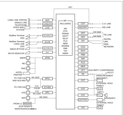
Figure 2-1 shows a typical trunking diagram for the PBX.
Figure 2-1 PBX Trunking Diagram
MODEM
Note 1: An external Modem is not required when the Built-In Modem on the MP is used.
Note 2: The equipment marked with (*) is provided by the customer.
4W E&M 2W E&M RS 232C V.11 TCP/IP V.11 RS-232C RS 232C LONG LINE STATION
SINGLE LINE TELEPHONE VOICE MAIL SYSTEM Multiline Terminal DSS Multiline Terminal LONG LINE DSS SN610 ATTCON SMDR PMS HOTEL PRINTER
PC FOR OAI AND ACD-MIS
PC FOR OAI
DTE
MAT
FROM LC
(FOR REMOTE MAINTENANCE)Note 1
DPC ETHER AP01 AP00 DLCC/DLCF DLCB DLCA/DLCJ LCD LCD/LCS AUC PFT MP INCLUDING SW DTG PBSND 16CFT MLDT PLO MEM MODEM PBR TNT SMDR COT AUC/DIT ODT ODT DTI CCH DCH PBR DAT PLO MFR CFT DK COT COT COT COT/TNT TNT EXTERNAL HOLD TONE(*) (*) SPEAKER(*) AMP(*) EXTERNAL HOLD TONE(*) ANNOUNCEMENT MACHINE(*) KEY(*) 6/10 PARTY CONFERENCE
DIGITAL LINK ISDN NETWORK TIE LINE DID LINE C.O. LINE MCI
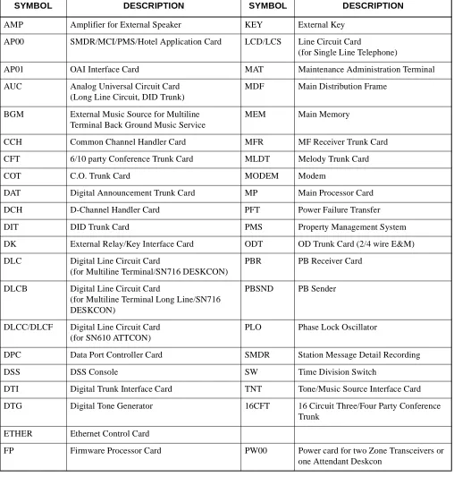
Note : Refer to NAP-200-008 and the Circuit Card Manual for details of circuit cards.
AP00 SMDR/MCI/PMS/Hotel Application Card LCD/LCS Line Circuit Card
(for Single Line Telephone)
AP01 OAI Interface Card MAT Maintenance Administration Terminal
AUC Analog Universal Circuit Card (Long Line Circuit, DID Trunk)
MDF Main Distribution Frame
BGM External Music Source for Multiline Terminal Back Ground Music Service
MEM Main Memory
CCH Common Channel Handler Card MFR MF Receiver Trunk Card
CFT 6/10 party Conference Trunk Card MLDT Melody Trunk Card
COT C.O. Trunk Card MODEM Modem
DAT Digital Announcement Trunk Card MP Main Processor Card
DCH D-Channel Handler Card PFT Power Failure Transfer
DIT DID Trunk Card PMS Property Management System
DK External Relay/Key Interface Card ODT OD Trunk Card (2/4 wire E&M)
DLC Digital Line Circuit Card
(for Multiline Terminal/SN716 DESKCON)
PBR PB Receiver Card
DLCB Digital Line Circuit Card
(for Multiline Terminal Long Line/SN716 DESKCON)
PBSND PB Sender
DLCC/DLCF Digital Line Circuit Card (for SN610 ATTCON)
PLO Phase Lock Oscillator
DPC Data Port Controller Card SMDR Station Message Detail Recording
DSS DSS Console SW Time Division Switch
DTI Digital Trunk Interface Card TNT Tone/Music Source Interface Card
DTG Digital Tone Generator 16CFT 16 Circuit Three/Four Party Conference Trunk
ETHER Ethernet Control Card
• Wall-Mounting Installation
• 19-Inch Rack-Mounting Installation
• Desk Top Installation
This equipment can only be serviced by a qualified service person.
Examples of system configurations for each installation method are shown in Figure 2-2 through Figure 2-5.
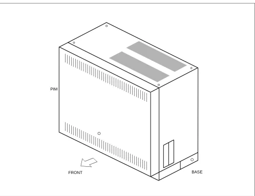
Figure 2-2 Floor Standing Installation
BASE PIM
Figure 2-3 Wall-Mounting Installation
Figure 2-4 19-Inch Rack-Mounting Installation
PIM
19”BRACKET (F)
•
3.1 Functional Outline of Modules
Table 2-2 shows the functional outline of the modules.
Table 2-2 Functional Outline of Modules
MODULES FUNCTIONAL
NAME FUNCTIONAL OUTLINE
SN1308 PIMQ-UA PIM
Port Interface Module (PIM)
A PIM provides 13 card slot for common control, Line/Trunk, and Applica-tion Processor (AP) cards. It also houses a AC/DC Power Supply and op-tional batteries for protection from short-term power interruption (standard).
Three champ connectors for line/trunk (LTC0 to 2) and a connector for Pow-er (PWR) are located at the lowPow-er front side of the PIM.
A PIM provides a maximum of 11 card slots for line/trunk (LT) cards. At maximum configuration, the system is comprised of 1 PIM and it provides 72 ports.
SN1228 MDFM-A MDFM
Main Distribution Frame Module (MDFM)
The MDFM is available for floor standing or IEC standard 19 inch rack mounting. (When the system is Wall Mounting or Desk Top configuration, the MDFM can not install with PIM.)
SN1177 BATTM-A BATTM
The BATTM is an optional module for installing optional long-term back-up batteries.
The BATTM is available for floor standing or IEC standard 19-inch rack mounting. (When the system is Wall Mounting or Desk Top configuration, the BATTM can not install with PIM.)
Requirements for batteries installed in the BATTM are as follows: • Battery Type : Lead-Acid
3.3 Functional Outline of Circuit Cards
3.3.1 Control Circuit Card
Table 2-4 shows the functional outline of each control circuit card.
Table 2-3 Functional Outline of Installation Hardware INSTALLATION
HARDWARE
FUNCTIONAL
NAME FUNCTIONAL OUTLINE
SN1225 BASE-A BASE Base Unit (includes Top Cover)
The Base Unit and Top Cover is required for PIM.
RACK PARTS RACK PARTS
Mounting Brackets (RACK PARTS)
The RACK PARTS are sets of hardware for floor standing and wall mount, which will be installed at the rear side of PIM.
The RACK PARTS must be installed, when the system is 3 modules.
COVER PARTS (B)
TOP BOTTOM
COVER
Bottom Cover (includes Top Cover)
The Bottom Cover and Top Cover is used when using 19-inch Rack mount-ing and Desk Top installation.
One sets of Bottom Cover and 4-Rubber Foots are required for Desk Top in-stallation with PIM.
19” BRACKET (F) 19”
BRACKET(F)
19-inch Bracket
The 19-inch Bracket is sets of hardware to mount the PIM, MDFM and/or BATTM in the IEC standard 19-inch rack. One set of 19-inch Bracket is re-quired for the PIM.
Table 2-4 Functional Outline of Control Circuit Cards
CARD NAME FUNCTIONAL
NAME FUNCTIONAL OUTLINE
PN-CP03 MP
Main Processor card.
This card is equipped with Memory, TDSW (1024CH × 1024CH), 16-Line CFT, DTMF Sender, Clock, PLO (receiver mode 2 ports), RS-232C Ports (2 ports) for MAT/Built-in SMDR, Modem for remote maintenance, and Mu-sic-On-Hold tone source (Melody IC/TNT), 4-circuit PBR (for PB calling or DID). This card is used on the basis of one per system.
PZ-PW86 PWR
Main power supply card.
Table 2-5 Functional Outline of Application Circuit Cards CARD NAME FUNCTIONAL
NAME FUNCTIONAL OUTLINE
PN-AP00-A AP00
Application Processor card.
This card is equipped with four RS-232C ports, and is used for SMDR, H/M Printer, PMS functions and MCI.
This card is used on the basis of one per system.
PN-AP01 AP01
Application Processor card.
This card is equipped with one RS-232C port and one Ethernet interface port, and is used for OAI function. Also, this card is used to expand authorization code and ACD. This card is used on the basis of one per system.
PN-BRTA BRI
Basic Rate (2B+D) Interface Trunk card. (S/T Interface)
This card has one circuit of Basic Rate interface and provides one 2-channel PCM dig-ital line.
PN-ME00 EXTMEM
Memory Expansion card.
This card is used with PN-AP00-A card for providing expansion memory.
This card can be equipped with an expansions SRAM card (1MB) as SMDR data mem-ory.
PN-CC00 ETHER
Ethernet Control card.
This card is used with the PN-AP01 card to accommodate the Ethernet, transmitting/re-ceiving a signal of TCP/IP protocol.
PN-CK00 PLO
Phase Locked Oscillator card.
This card is a phase locked oscillator for providing a synchronized clock signal with the network.
This card is used when the PBX is a master office or when the PBX requires two clock supply routes and those frequencies differ.
PN-24DTA/
PN-24DTA-A DTI
Digital Trunk Interface (23B+D, 1.5 Mbps) card. This card accommodates 24-channel, PCM digital lines.
PN-4RSTB MFR
4-line MF Receiver Trunk card.
This card is used for MF Signaling on Digital DID trunks. A maximum of four cards can be provided per one system, including the PN-4RSTC card.
PN-4RSTC CIR
4-line CALLER ID Receiver Trunk card.
This card is used for CALLER ID (CLASS SM) on analog trunks. A maximum of four cards can be provided per one system, including the PN-4RSTB card.
PN-SC00 CCH Common Channel Handler card.
This card transmits/receives signals on the common signaling channel of No. 7 CCIS.
PN-SC01 DCH D-channel Handler card.
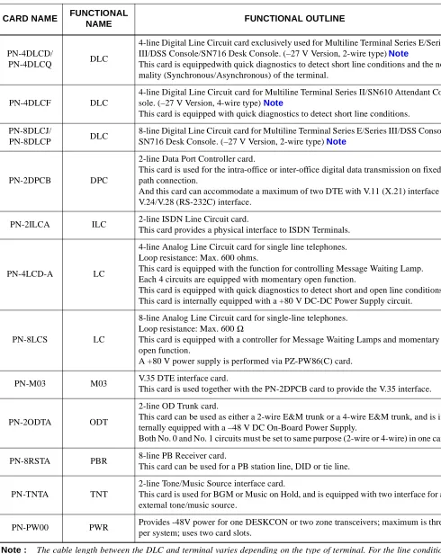
Table 2-6 Functional Outline of Line/Trunk Circuit Cards CARD NAME FUNCTIONAL
NAME FUNCTIONAL OUTLINE
PN-2AMPA AMP
2-line Amplifier Trunk card.
This card equipped with the functions of Echo Canceller (EC), Automatic Gain Control-ler (AGC) and Tone DisabControl-ler (TD).
PN-AUCA AUC
2-line Long-Line circuit card provided with the Power Failure Transfer (PFT) function. Line resistance in the case of a long-line circuit: Max. 2500 ohms (inclusive of the in-ternal resistance of the distant office equipment)
This card is internally equipped with a –48 V DC On-Board Power Supply. This card can also be used as a 2-line Direct Inward Dialling trunk card.
PN-CFTA CFT
Conference Trunk card
Use of one card:Can control a conference of up to six participants. Use of two cards:Can control a conference of up to ten participants.
PN-4COTB COT 4-line Central Office Trunk card (Ground Start/Loop Start trunk) equipped with the functions for loop detection, sending/detecting ground on Ring/Tip wire.
PN-4COTG COT 4-line Central Office Trunk card (Loop Start trunk) equipped with the functions for loop detection, receiving/sending the CALLER ID (CLASS SM) signal.
PN-2DATA DAT 2-line Digital Announcement Trunk card.
Duration: Max. 60 seconds.
PN-DK00 DK
Circuit card for External Relay Control/External Key Scan.
This card is provided with eight circuits, and can provide the above-mentioned control functions on a per circuit basis.
PN-4DITB DIT
4-line Direct In Dialing Trunk card.
This card is equipped with the function for loop detection, sending reverse signal and PB to DP signal conversion.
This card is internally equipped with –48 V DC On-Board Power supply.
PN-2DLCB DLC
2-line Digital Line Circuit card for Multiline Terminal Series E/Series III/DSS Console/ SN716 Desk Console.
(–48V Version, 2-wire type) Note
This card is equipped with quick diagnostics to detect short line conditions and the nor-mality (Synchronous/Asynchronous) of the terminal.
This card is internally equipped with a –48 V DC On-Board Power Supply.
PN-2DLCC DLC
2-line Digital Line Circuit card for Multiline Terminal Series II/SN610 Attendant Con-sole. (–48 V Version, 4-wire type) Note
This card is equipped with quick diagnostics to detect short line conditions and the nor-mality (Synchronous/Asynchronous) of the terminal.
This card is internally equipped with –48 V On-Board Power Supply.
III/Electra-PN-4DLCD/
PN-4DLCQ DLC
4-line Digital Line Circuit card exclusively used for Multiline Terminal Series E/Series III/DSS Console/SN716 Desk Console. (–27 V Version, 2-wire type) Note
This card is equippedwith quick diagnostics to detect short line conditions and the nor-mality (Synchronous/Asynchronous) of the terminal.
PN-4DLCF DLC
4-line Digital Line Circuit card for Multiline Terminal Series II/SN610 Attendant Con-sole. (–27 V Version, 4-wire type) Note
This card is equipped with quick diagnostics to detect short line conditions.
PN-8DLCJ/
PN-8DLCP DLC
8-line Digital Line Circuit card for Multiline Terminal Series E/Series III/DSS Console/ SN716 Desk Console. (–27 V Version, 2-wire type) Note
PN-2DPCB DPC
2-line Data Port Controller card.
This card is used for the intra-office or inter-office digital data transmission on fixed path connection.
And this card can accommodate a maximum of two DTE with V.11 (X.21) interface or V.24/V.28 (RS-232C) interface.
PN-2ILCA ILC 2-line ISDN Line Circuit card.
This card provides a physical interface to ISDN Terminals.
PN-4LCD-A LC
4-line Analog Line Circuit card for single line telephones. Loop resistance: Max. 600 ohms.
This card is equipped with the function for controlling Message Waiting Lamp. Each 4 circuits are equipped with momentary open function.
This card is equipped with quick diagnostics to detect short and open line conditions. This card is internally equipped with a +80 V DC-DC Power Supply circuit.
PN-8LCS LC
8-line Analog Line Circuit card for single-line telephones. Loop resistance: Max. 600 Ω
This card is equipped with a controller for Message Waiting Lamps and momentary open function.
A +80 V power supply is performed via PZ-PW86(C) card.
PN-M03 M03 V.35 DTE interface card.
This card is used together with the PN-2DPCB card to provide the V.35 interface.
PN-2ODTA ODT
2-line OD Trunk card.
This card can be used as either a 2-wire E&M trunk or a 4-wire E&M trunk, and is in-ternally equipped with a –48 V DC On-Board Power Supply.
Both No. 0 and No. 1 circuits must be set to same purpose (2-wire or 4-wire) in one card.
PN-8RSTA PBR 8-line PB Receiver card.
This card can be used for a PB station line, DID or tie line.
PN-TNTA TNT
2-line Tone/Music Source interface card.
This card is used for BGM or Music on Hold, and is equipped with two interface for an external tone/music source.
DTP-8-1
PN-8DLCJ/8DLCP
(STANDARD) 984ft. (300m)
Note 1 PN-4DLCD/4DLCQ (STANDARD) 984ft. (300m) [3937ft. (1200m)] PN-2DLCB/2DLCN (LONG) 2788ft. (850m) [3937ft. (1200m)] DTP-8D-1 PN-8DLCJ/8DLCP
(STANDARD) 984ft. (300m)
Note 1 PN-4DLCD/4DLCQ (STANDARD) 984ft. (300m) [3937ft. (1200m)] PN-2DLCB/2DLCN (LONG) 2788ft. (850m) [3937ft. (1200m)] DTP-16-1 PN-8DLCJ/8DLCP
(STANDARD) 656ft. (200m)
Note 1 PN-4DLCD/4DLCQ (STANDARD) 656ft. (200m) [3937ft. (1200m)] PN-2DLCB/2DLCN (LONG) 2788ft. (850m) [3937ft. (1200m)] DTP-16D-1 PN-8DLCJ/8DLCP
(STANDARD) 656ft. (200m)
Note 1 PN-4DLCD/4DLCQ (STANDARD) 656ft. (200m) [3937ft. (1200m)] PN-2DLCB/2DLCN (LONG) 2788ft. (850m) [3937ft. (1200m)] DTP-32-1 PN-8DLCJ/8DLCP
(STANDARD) 656ft. (200m)
Note 1 PN-4DLCD/4DLCQ (STANDARD) 656ft. (200m) [3937ft. (1200m)] PN-2DLCB/2DLCN (LONG) 2788ft. (850m) [3937ft. (1200m)] DTP-32D-1 PN-8DLCJ/8DLCP
(STANDARD) 656ft. (200m)
Note 1 PN-4DLCD/4DLCQ (STANDARD) 656ft. (200m) [3937ft. (1200m)] PN-2DLCB/2DLCN (LONG) 2788ft. (850m) [3937ft. (1200m)] DSS/BLF Console PN-8DLCJ/8DLCP
(STANDARD) 984ft. (300m) Note 1
PN-4DLCD/4DLCQ
* The value in the [ ] shows the cable length when using the long line function.
Note 1: When using PN-8DLCJ/8DLCP card, it is not available long line function. ETJ-8-1
PN-8DLCJ/8DLCP
(STANDARD) 984ft. (300m) Note 1
PN-4DLCD/4DLCQ (STANDARD) 984ft. (300m) [3937ft. (1200m)] PN-2DLCB/2DLCN (LONG) 2788ft. (850m) [3937ft. (1200m)] ETJ-16DC-1 PN-8DLCJ/8DLCP
(STANDARD) 656ft. (200m) Note 1
PN-4DLCD/4DLCQ (STANDARD) 656ft. (200m) [3937ft. (1200m)] PN-2DLCB/2DLCN (LONG) 2788ft. (850m) [3937ft. (1200m)] ETJ-16DD-1 PN-8DLCJ/8DLCP
(STANDARD) 656ft. (200m) Note 1
PN-4DLCD/4DLCQ (STANDARD) 656ft. (200m) [3937ft. (1200m)] PN-2DLCB/2DLCN (LONG) 2788ft. (850m) [3937ft. (1200m)] ETJ-24DS-1 PN-8DLCJ/8DLCP
(STANDARD) 492ft. (150m) Note 1
PN-4DLCD/4DLCQ (STANDARD) 492ft. (150m) [3937ft. (1200m)] PN-2DLCB/2DLCN (LONG) 2788ft. (850m) [3937ft. (1200m)] SN610 ATTCON PN-2DLCC
(LONG) 3937ft. (1200m)
PN-4DLCF
(STANDARD) 984ft. (300m)
SN716 DESKCON
PN-8DLCJ/8DLCP 984ft. (300m)
PN-4DLCD/4DLCQ 1148ft. (350m) Note 3 [3937ft. (1200m)]
Figure 2-6 below shows circuit card mounting slots allocated in the PIM, on the basis of circuit card type.
Figure 2-6 Circuit Card Mounting Slots
LT00 - LT10 : Line/trunk circuit card mounting slots
• LT00 - LT08 : All of line/trunk circuit card can be mounted in these slots • LT09 : All of line/trunk circuit card can be mounted in this slot
(But a maximum of 4 circuits can be assigned for the circuit card with cabling.)
• LT10 : Line/trunk circuit card with cabling can not be mounted in this slot, since this slot has no connection to the MDF via the backplane.
AP0 - AP5 : Application circuit card mounting slots MP : PN-CP03 mounting slot
PWR : PZ-PW86 mounting slot
*1 Either line/trunk circuit cards or application circuit cards can be mounted in these slots.
*2 When mounting the circuit card with cabling in LT08 slot and LT09 slot, the circuit card must be mounted with the following conditions.
(1) When mounting PN-8LC/PN-8DLC card in LT08 slot, the circuit card with cabling can not be mounted in LT09 slot.
(2) The application circuit card type PN-CC00 can be mounted in any LT/AP slot, but it occupies two slot po-sitions; i.e. the slot immediately to its right must be vacant.
(3) The PN-PW00 can be mounted in any LT/AP slot, but it occupies two slot positions; i.e. the slot immedi-ately to it’s left must be vacant.
1.1 Grounding Requirements
The system grounding must have a specific ground resistance and AC noise level, and is to be connected to a pre-determined terminal in the PBX. Standard grounding requirements are as follows:
• Communication grounding: Less than 10 ohm
• Protective ground for PIM: Less than 10 ohm
Note : The AC ripple on these various grounds should be less than 0.5 Vp-p.
Figure 3-1 Static Electricity Guard
CARD FRONT PBX
WRIST STRAP
• WHEN PLUGGING/UNPLUGGING A CIRCUIT CARD
• WHEN HOLDING A CIRCUIT CARD
FRAME GROUND SCREW
CONNECT THE GROUND WIRE TO THE FRAME EARTH OF THE EQUIPMENT.
Figure 3-1 Static Electricity Guard (Continued)
WEAR A WRIST STRAP AND PERFORM THE WORK ON A GROUNDED
CONDUCTIVE WORK SURFACE.
WHEN CARRYING A CIRCUIT CARD AROUND, KEEP THE CARD IN A CONDUCTIVE POLYETHYLENE BAG. CONDUCTIVE
POLYETHYLENE BAG
Table 3-1 Removing/Inserting Circuit Cards Procedure
CIRCUIT CARD
PROCEDURE
CONDITION
INSERT REMOVE
• PN-CP03 (MP) • PZ-PW86 (PWR)
• PN-PW00 (EXTPWR)
Power off
↓
Insert
↓
Power on
Power off
↓
Remove
↓
Power on
Always insert or remove these circuit cards with power off to prevent damage to the card or other system circuitry.
• PN-AP00 (AP00)
• PN-ME00 (EXTMEM)
• PN-BRTA (BRT) • PN-24DTA-A (DTI) • PN-SC00 (CCH) • PN-SC01 (DCH) • PN-SC02 (ICH) • PN-CK00 (PLO) • PN-4RSTB (MFR) • PN-4RSTC (CIR)
Power off or MB switch on
↓
Insert
↓
Power on or MB switch off
Power off or MB switch on
↓
Remove
↓
Power on
Always insert or remove these circuit cards under Make Busy condition or power off to prevent damage to the card or other system circuitry.
• PN-AP01 (AP01) • PN-CC00 (ETHER) • PN-CC01 (ETHER)
CARD FRONT PBX
of each step. The NAP Number refers to the details for each procedure.
Figure 3-2 Procedure Flowchart
START
UNPACKING
MARKING AND DRILLING
INSTALLATION OF MAIN EQUIPMENT
CONNECTION OF BATTERY
TERMINATION OF CABLES ON THE MDF
CABLE RUNNING TO THE MDF
SWITCH SETTING OF CIRCUIT CARDS
A
NAP- 200-001
NAP- 200-002
NAP- 200-003
NAP- 200-004
NAP- 200-005
NAP- 200-006
NAP- 200-008
INSTALLATION OF
Figure 3-2 Procedure Flowchart (Continued)
The mark shown below is attached to the NAP sheet for each procedure in which circuit cards are handled. When doing such a procedure, the installer must perform the procedure with caution, to prevent damage caused by static electricity (See Section 1.2 Static Electricity Guard in this chapter).
END
MOUNTING OF THE FRONT COVER CIRCUIT CARDS
SYSYEM INITIALIZATION AND
SYSTEM DATA ENTRY
OPERATION TEST
NAP- 200-010
NAP- 200-011
NAP- 200-012
CLEANING AND VISUAL CHECK
NAP- 200-013
ATTENTION
Contents Static Sensitive Handling
1. UNPACKING PROCEDURE
(1) Check the received quantity of packages containing the PBX system with the description on the shipping document.
(2) Check the packaging for external damage done by transportation and record it as necessary.
(3) Unpack the packaging.
• For unpacking the packages containing circuit cards, a grounded wrist strap should be worn.
(4) Check the quantity of equipment and materials unpacked with the shipping document.
(5) Perform visual inspection, checking for the following items.
• Modules Overall distortion.
Scratches and dents on the surface.
Scratches and cracks on the PIM Backplane.
Broken or bent pins on the PIM Backplane.
• Covers Scratches and dents.
• Circuit Cards Overall distortion
Scratches and cracks
Loss, or damage of parts on the circuit cards.
• Attendant Console Scratches and cracks on the keyboard
Overall distortion
Damage to keys and lamps.
Figure 001-1 Unpacking of Main Equipment
ACCESSORIES
1. CONFIRMATION OF THE EQUIPMENT LAYOUT
Install the equipment in an area which provides adequate ventilation and is easily accessible to service personnel.
2. MARKING
2.1 Floor Standing
• By referring to Figure 002-1, mark the installation holes for the main equipment.
• Mark the installation holes for the external MDF, if required.
Figure 002-1 Floor Marking for Main Equipment
356 mm (14.0 inch) 430 mm (16.9 inch)
FRONT RACK PARTS 39 mm (1.5 inch)
110 mm (4.3 inch)
35 mm (1.4 inch)
37 mm (1.6 inch) 37 mm (1.6 inch)
40 mm (1.6 inch)
2.2 Wall-Mounting
• Locate and mark the wall mounting points as shown in Figure 002-2.
Figure 002-2 Wall Mounting Points
382 mm (15.0 inch)
250 mm (9.8 inch)
86 mm (3.4 inch)
430 mm (16.9 inch)
PBX BOTTOM POSITION
BOTTOM POSITION
BOTTOM
ANCHOR (x4)
350 mm (13.8 inch)
390 mm (15.4 inch)
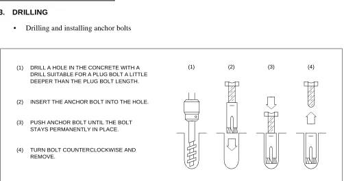
3. DRILLING
• Drilling and installing anchor bolts
Figure 002-3 Instruction for Anchor Bolt
(1) DRILL A HOLE IN THE CONCRETE WITH A DRILL SUITABLE FOR A PLUG BOLT A LITTLE DEEPER THAN THE PLUG BOLT LENGTH.
(2) INSERT THE ANCHOR BOLT INTO THE HOLE.
(3) PUSH ANCHOR BOLT UNTIL THE BOLT STAYS PERMANENTLY IN PLACE.
(4) TURN BOLT COUNTERCLOCKWISE AND REMOVE.
Install the main equipment according to the desired procedure for either Floor Standing, Wall-Mounting, 19-Inch Rack-Mounting or Desk Top installation.
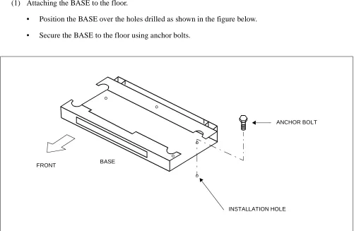
1. FLOOR STANDING INSTALLATION (1) Attaching the BASE to the floor.
• Position the BASE over the holes drilled as shown in the figure below.
• Secure the BASE to the floor using anchor bolts.
Figure 003-1 Securing of the BASE
BASE FRONT
INSTALLATION HOLE
(2) Mount the PIM on the BASE, and connect them together using 3 bolts (provided).
Figure 003-2 Mounting of the PIM
PIM
BASE
(3) Position the TOP COVER on the PIM, and connect them together with 4 screws (provided).
Figure 003-3 Mounting of the TOP COVER
TOP COVER
PIM
2. WALL-MOUNTING INSTALLATION
(1) Using four appropriate fasteners (locally provided; see Table 003-1) for the type of wall constructions, se-cure the RACK PARTS as shown in Figure 003-4. For the wall mounting points, refer to Figure 002-2 in NAP-200-002.
Note : The wall types are listed in recommendation order. Concrete is the most secure and plaster board is the least secure.
Table 003-1 Recommended Fasteners
WALL TYPE RECOMMENDED FASTENER
PLASTER BOARD [THICKNESS Min. 9.6 mm (0.38 inch)]
MOLLY ANCHOR TYPE Min. 3.5 mm (0.14 inch) DIA. Max. 4.5 mm (0.17 inch) DIA
WOOD WOOD TYPE SCREWS
Min. 3.5 mm (0.14 inch) DIA Max. 4.5 mm (0.17 inch) DIA
CONCRETE ANCHOR BOLT TYPE
(2) Attach four M4 machine screws (provided) to the RACK PARTS.
Figure 003-4 Screwing the RACK PARTS to a Wall
SCREW-A (4 per PIM)
SECURING RACK PARTS TO WALL (LOCALLY PROVIDED)
(SEE TABLE 003-1)
M4 MACHINE SCREW-B (4 per PIM) SECURED TO RACK PARTS (PROVIDED WITH RACK PARTS)
(WALL)
382 mm(15.0 inch)
250 mm
ANCHOR (4 per PIM)
RACK PARTS
(9.8 inch)
(3) For proper mounting of PIM, approx. 4 mm (0.2 inch) spacing should be provided between the inner face of the M4 machine screw and the RACK PARTS front channel as shown in Figure 003-5.
Align and insert the key hole slots of the rear cover of PIM to the machine screws secured.
Figure 003-5 Mounting the PIM to the RACK PARTS
(PIM)
APPROX. 4 mm (0.2 inch)
(WALL)
SCREW-A (4 per PIM)
RACK PARTS M4 MACHINE SCREW-B (4 per PIM)
(REAR COVER)
(LOCALLY PROVIDED)
(4) After hanging PIM onto the RACK PARTS, tighten each M4 machine screw using a phillips screw driver.
Figure 003-6 Screwing the PIM to the RACK PARTS
M4 MACHINE SCREW-B (X4)
(5) Connect the TOP COVER, BOTTOM COVER and AC CORD-A-U to the PIM. The AC CORD-A-U is pre-installed with the BOTTOM COVER.
Figure 003-7 Connecting the Covers and AC CORD to the PIM
TOP COVER
TO PZ-PW86 PIM
AC CORD-A-U
3. 19-INCH RACK-MOUNTING INSTALLATION
(1) Before mounting the PIM, connect the TOP COVER, BOTTOM COVER and AC CORD-A-U to the PIM. The AC CORD-A-U is pre-installed with the BOTTOM COVER.
TOP COVER
TO PZ-PW86 PIM
AC CORD-A-U
(2) Secure the 19” BRACKET (F) to the 19-inch Rack as shown in Figure 003-9 .
(3) Mount the PIM on the 19” BRACKET (F) as shown in Figure 003-9 . Then, secure the PIM to the 19” BRACKET (F) as shown in Figure 003-9 .
A
B C
A B
PIM 19” BRACKET(F)
C
FRONT
19” BRACKET(F)
19-INCH RACK
PIM BOTTOM COVER
4. DESK TOP INSTALLATION
(1) Connect the TOP COVER, BOTTOM COVER and AC CORD-A-U to the PIM. The AC CORD-A-U is pre-installed with the BOTTOM COVER.
TOP COVER
TO PZ-PW86 PIM
AC CORD-A-U
(2) Connect the RUBBER FOOT to the PIM.
PUSH
PIN
RUBBER FOOT BOTTOM
5. AC POWER CABLING
(1) The cable connections on the PZ-PW86 card are shown below.
PZ-PW86
MJ MN ON BATTERY MODE SWITCH
GND Note 2
FG -27V
PWR CNT CA-A
PWR CA-A
BATTERY CABLE/PWR CA-A TO PWR1
TO OTHER
AC CORD-A
TO AC MAINS INPUT TO POWER OUTPUT
POWER OUTPUT
TO PWR0A CONNECTOR TO PWR0B CONNECTOR CABLE (+5V, -27V,E)
CABLE (CR, E)
CONNECTOR
PZ-PW86 TO AUXILIARY
BATTERY CONNECTOR (BATT2)
ON OFF
100/120V
240V EQUIPMENT
TO BATTERY OR OTHER PZ-PW86 GREEN WHITE BLACK AC CORD-B OR
TO THE TERMINAL BLOCK AT BASE
FRAME GROUND TERMINAL ON THE CHASSIS
CAUTION: Set the appropriate voltage before turning on the SW switch.
Note 1: Follow the Label on the front plate of the PZ-PW86(C).
Note 2: If GND (Signal GND) has to be separated from FG (Frame GND), remove the link between GND and FG terminals.
– O
BATTERY CONNECTOR (BATT1) 1 2 ON L N NOMINAL AC INPUT TO TERMINAL MARKED: ON BASE TO PWR0D CONNECTOR
POWER OUTPUT CABLE (+80V, E)
PZ-PW86(D)
MJ MN ON
BATTERY MODE SWITCH
GND Note 2 FG
–27V
PWR CNT CA-A TO PWR1
AC CORD-A TO AC MAINS INPUT TO
POWER OUTPUT
TO PWR0A CONNECTOR TO PWR0B CONNECTOR POWER OUTPUT
CABLE (CR, E)
CONNECTOR TO AUXILIARY
BATTERY CONNECTOR (BATT2)
ON OFF 100/120V 240V EQUIPMENT GREEN WHITE BLACK AC CORD-B OR
(FOR 1-PIM SYSTEMS)
TO THE TERMINAL BLOCK AT BASE (FOR MULTIPLE PIM SYSTEMS)
FRAME GROUND
Note 1: Follow the Label on Front Plate of PZ-PW86(D).
Note 2: If GND (Signal GND) has to be separat-ed from FG (Frame GND), remove the link between GND and FG terminal. 1: NO CONNECTION
OFF-FL./FLOAT 1 2: ON-EQ./FLOAT 2
– O 1
2 ON
TERMINAL ON THE
(See Figure 003-12) Note 1
TO PWR0D CONNECTOR
POWER OUTPUT CABLE (+90V,E)
TO OTHER PZ-PW86
PWR CA-A
TO BATTERY OR OTHER PZ-PW86
BATTERY CONNECTOR (BATT1) BATTERY CABLE/PWR CA-A
CHASSIS (FOR 1-PIM SYSTEMS)
L N NOMINAL AC INPUT TO TERMINAL MARKED: ON BASE
• PZ-PW86(D)
CAUTION: Set the appropriate volt-age before turning on the SW switch.
(2) Confirm the connection of the PWR CNT CA-A and power output cables (These cables are pre-installed).
Figure 003-13 Cable Connection between the PZ-PW86 and the BWB
LTC CONNECTOR AREA PIM
BWB (Back Wiring Board)
PZ-PW86
PWR0B PWR0A
PWR1
POWER OUTPUT
POWER OUTPUT CARD SLOT AREA
PWR0C
PWR0D
PWR CNT CA-A
CABLE (+5V, -27V, E)
CABLE (CR, E) POWER OUTPUT
(3) AC Power Cable Wiring
(a) The AC CORD-B and the AC Power Cable Wiring to the FG, NEUTRAL and LINE terminals inside the BASE are shown in Figure 003-15.
Figure 003-14 AC Power Cable Wiring
TO GROUND TERMINAL
FRONT SEE FIGURE 003-15
3P AC POWER CABLE PIM
BASE
(b) Secure the AC CORD-B cables to the FG, NEUTRAL and LINE terminals. The 3P AC Power Cable and the FG Cable are pre-installed with the BASE.
Figure 003-15 Screwing the AC CORD-B to the Terminals FG
NEUTRAL
LINE
BASE
3P AC POWER CABLE TO 120/240 V AC SOURCE POWER AC POWER
KNOCK OUT HOLE
(PROVIDED WITH BASE) FG CABLE
(PROVIDED WITH BASE)
PIM AC CORD-B
PUSH PULL
: INSERT THE AC CORD : FIXED THE AC CORD
CORD BUSH
(PROVIDED WITH BASE)
SUPPLEMENTARY GROUND (TO COLD WATER PIPE, ETC.)
6. MDFM/BATTM INSTALLATION
When installing the MDFM and BATTM, follow the installation below.
(1) Connect the RACK PARTS to the rear side of the BASE using the M5 Machine screws (provided).
Note : This installation procedure is required when the system is 3 modules (PIM + MDFM + BATTM).
RACK PARTS
BASE
REAR M5 MACHINE SCREW-C
(X2/JOINT AREA)
(2) Connect the RACK PARTS to each other.
Note : This installation procedure is required when the system is 3 modules (PIM + MDFM + BATTM).
RACK PARTS
REAR RACK PARTS
(3) Connect the PIM to the RACK PARTS using the 4 screws provided with the RACK PARTS.
Note : This installation procedure is required when the system is 3 modules (PIM + MDFM + BATTM).
Figure 003-18 Connection of the PIM and the RACK PARTS
REAR
PIM Note
BASE
(4) Connect the PIM to the MDFM/BATTM as shown in Figure 003-19. Then, connect the TOP COVER to the PIM as shown in Figure 003-3.
PIM
MDFM Note
FRONT
1. BATTERY CONNECTION
CAUTION 1: 24V batteries must be used in this system.
CAUTION 2: If battery terminals (+, –) contact with the module under connecting the battery cable to the PZ-PW86 card, the PZ-PZ-PW86 card or the BWB may be broken. Therefore, the installer must per-form work in accordance with the following steps when mounting or removing the batteries.
• When mounting batteries:
(1) Connect the battery cable to the batteries.
(2) Mount the batteries into the appointed position of the PIM or the BATTM.
(3) Connect the battery cable to the PZ-PW86 card.
• When removing batteries:
(1) Disconnect the battery cable from the PZ-PW86 card.
(2) Remove the batteries from the PIM or the BATTM.
Recommended Battery
Internal Battery : YUASA MATUSHITA
type type
NPH-3.2-12 LCR-12V-3.4NE
External Battery : YUASA MATUSHITA
type type
CAUTION 3: Battery Replacement Table and Battery Warnings
The label, which shows battery replacement table and battery warnings, is attached to the re-verse side of Front Cover for PIM and BATTM.
During the battery installation process, always observe the warning statements. When replacing batteries, adhere to the battery replacement table to increase battery life and to insure safe op-eration.
25° C ~ 30° C
2.0 ~ 2.5
(77° C ~ 86° F)
LABEL PIM/BATTM
FRONT COVER
BATTERY REPLACEMENT TABLE INSTALLATION DATE:
AMBIENT TEMPERATURE
25° C
(77° F)
REPLACEMENT
INTERVAL 2.5 ~ 3.0 1.5 ~ 2.0
CAUTION TO PREVENT INJURY AND SKIN BURN,PAY ATTENTION TO THE FOLLOWING. o DO NOT STRIKE A MATCH OR CAUSE A SPARK IN
VICINITY OF BATTERY.
o PLACE THE EQUIPMENT WELL VENTILATED AREA.
o DO NOT SHORT.
o REPLACE BATTERY ONLY AFTER BATTERY GASES HAVE BEEN DISPERSED.
o ELECTROLYTE LEAKAGE OR OTHER HAZARDS MAY RESULT IF THE BATTERY IS NOT REPLACED IN ACCORDANCE WITH THE SPECIFIED INTER-VALS.
(86° C ~ 104° F)
30° C ~ 40° C
1.1 Internal Battery Connection
(1) Mount the battery unit (24 V DC, 3.4 AH) into the PIM.
FRONT 67mm
DIMENSION OF BATTERY BATTERY UNIT (24V DC, 3.4AH) (LOCALLY PROVIDED)
(2.6 inch)
134mm (5.3 inch) 60mm
(2.4 inch)
PIM
(2) Plug the battery cable connector into the BATT1 connector on the PZ-PW86 as shown in Figure 004-2.
(3) Secure the batteries and battery cable using tie wraps.
Figure 004-2 Internal Battery Connection
PLUG IN TO BATT 1 CONNECTOR ON PZ-PW86
FRONT
TIE WRAP BASE
1.2 Battery Connection in the BATTM
(1) Connect the battery cables to the batteries, and mount the battery units (24 V DC, 24AH per unit) into the Battery Module (BATTM). See Figure 004-3.
TO PZ-PW86 IN PIM TO PZ-PW86 IN PIM
BATTERY CABLE
BATTERY UNIT (24 V DC, 24AH)
FRONT
1. MDF CABLE
To facilitate the termination of the 25 pair cables (MDF cables) from the system to the MDF, the length of each cable to be used should be predetermined according to the distance between the MDF and the system. Each cable should be labeled at both ends using a cable number or cable designation as shown in Figure 005-1.
FROM CABLE
NUMBER TO
CABLE DESTINATION MODULE CONNECTION
PIM0
LTC0 1
MDF
0 LTC0
LTC1 2 0 LTC1
LTC2 3 0 LTC2
TO PIM
CHAMP CONNECTOR
TWISTED 25 PAIR CABLES
2. INSTALLATION OF EXTERNAL MDF
• Secure the external MDF onto the floor or mount the MDF onto the wall.
• Mount the required MDF components.
• If required, install the cable ducts for the cables to be laid between the MDF and the Main Equipment. In this case, confirm the locations of the cable holes for the Main Equipment. See Figure 005-2.
FRONT
430 mm (16.9 inch) RACK PARTS
214 mm (8.4 inch)
3. CABLE RUNNING TO THE EXTERNAL MDF
(1) Bring the MDF cable up to the Main Equipment through the cable hole(s) of the BASE.
(2) Connect the champ connector of each MDF cable to an LTC connector located on a PIM using the screws provided, as shown in Figure 005-3.
(3) Pare the sheath of each MDF cable and secure the shield to the front bracket on the PIM using tie wraps, as shown in Figure 005-3.
LTC CONNECTOR
CHAMP CONNECTOR
FRONT
TO MDF BASE
PIM
PBX
TIE WRAP SHIELD
PIM
MDF CABLE
4. CABLE RUNNING TO THE MDFM
(1) Connect the champ connector of each MDF cable to an LTC connector located on a PIM using the screws provided, as shown in Figure 005-4.
(2) Pare the sheath of each MDF cable and secure the shield to the front bracket on the PIM using tie wraps, as shown in Figure 005-4.
LTC CONNECTOR
CHAMP CONNECTOR
FRONT
TO STATION, etc. BASE
MDFM PIM
PBX
TIE WRAP SHIELD
PIM
MDF CABLE
(3) Connect the MDF cables to the MDF connectors in the MDFM.
LTC0
LTC1
LTC2
PIM BWB
MDF CABLE MDF CONNECTOR
MDFM
1. CABLE CONNECTION TO THE MDF
(1) Connect the cables to the MDF referring to Figure 006-1 and Table 006-1.
Figure 006-1 Card Slots and LTC Connectors Location (PIM0)
Note : When using the internal DTMF Receiver on the MP card, assign the Card No. E200 to the LEN No. 0124.
Table 006-1 LTC Connector Accommodation
LTC CONNECTOR CARD SLOT NUMBER REMARKS
LTC0 LT00 ~ LT05
LTC1 LT06 ~ LT09, LT10/AP0, LT11/AP1
LTC2 LT12/AP2 ~ LT15/AP5, AP6
(2) Connect the cables to the MDF referring to Figure 006-2 and Table 006-2.
Figure 006-2 Card Slots and LTC Connectors Location (PIM1)
Note : When using the internal DTMF Receiver on the MP card, assign the Card No. E200 to the LEN No. 0124.
Table 006-2 LTC Connector Accommodation
LTC CONNECTOR CARD SLOT NUMBER REMARKS
LTC0 LT00 ~ LT02
LTC1 LT03 ~ LT05
LTC2 LT06/AP0 ~ LT09/AP3
LT
09
/A
P
3
LT
08
/A
P
2
LT
07
/A
P
1
LTC1
LTC0 LTC2
BWB
FRONT
P W R
LT
1
0
/A
P
4
LT
00
LT
01
LT
02
LT
03
LT
04
LT
05
LT
06
/A
P
0
AP5 MP
(3) The figure below shows the relationship between each Line Equipment Number (LEN) and each Card Slot Number (LT Number).
(a) LEN 0000 ~ 0143
Note 1: Do not mount line/trunk circuit card with cabling in this slot; this slot has no connection to the MDF via the backplane, except M03.
Note 2: When using the internal DTMF Receiver on the MP card, assign the Card No. E200 to the LEN No. 0124. 0079 0078 0077 0076 0075 0074 0073 0072 (LT01) 0087 0086 0085 0084 0083 0082 0081 0080 (LT02) 0095 0094 0093 0092 0091 0090 0089 0088 (LT03) 0103 0102 0101 0100 0099 0098 0097 0096 (LT04) 0111 0110 0109 0108 0107 0106 0105 0104 (LT05) 0119 0118 0117 0116 0115 0114 0113 0112 (LT06) 0127 0126 0125 0124 0123 0122 0121 0120 (LT07) 0135 0134 0133 0132 0131 0130 0129 0128 (LT08) _ _ _ _ 0139 0138 0137 0136 (LT09) _ _ _ _ 0143 0142 0141 0140 (LT10) 0003 0002 0001 0000 (LT00) 0007 0006 0005 0004 (LT01) 0011 0010 0009 0008 (LT02) 0015 0014 0013 0012 (LT03) 0019 0018 0017 0016 (LT04) 0023 0022 0021 0020 (LT05) 0027 0026 0025 0024 (LT06) 0031 0030 0029 0028 (LT07) 0035 0034 0033 0032 (LT08) 0039 0038 0037 0036 (LT09) 0043 0042 0041 0040 (LT10) 0047 0046 0045 0044 (LT11) 0051 0050 0049 0048 (LT12) 0055 0054 0053 0052 (LT13) 0059 0058 0057 0056 (LT14) 0063 0062 0061 0060 (LT15) 0071 0070 0069 0068 0067 0066 0065 0064 (LT00) PIM1
0 × × × 0 × × × 0 × × × 0 × × × 0 × × × 0 × × × 0 × × × 0 × × × (LT × ×)
LEN
(LINE EQUIPMENT NUMBER)
CARD SLOT NUMBER
Note 1
0 × × × 0 × × × 0 × × × 0 × × × (LT × ×)
LEN
(LINE EQUIPMENT NUMBER)
(4) The figure below shows the LTC Connector Pin Arrangement.
(a) PIM0 (LTC0 ~ LTC2)
LTC2
26 1 LEN0048
LT12/AP2
27 2 0049
28 3 0050
29 4 0051
30 5 0052
LT13/AP3
31 6 0053
32 7 0054
33 8 0055
34 9 0056
LT14/AP4
35 10 0057
36 11 0058
37 12 0059
38 13 0060
LT15/AP5
39 14 0061
40 15 0062
41 16 LEN0063 42 17 AP6 Note: 43 18 44 19 45 20 46 21 47 22 48 23 49 24 50 25 LTC0
26 1 LEN0000
LT00
27 2 0001
28 3 0002
29 4 0003
30 5 0004
LT01
31 6 0005
32 7 0006
33 8 0007
34 9 0008
LT02
35 10 0009
36 11 0010
37 12 0011
38 13 0012
LT03
39 14 0013
40 15 0014
41 16 0015
42 17 0016
LT04
43 18 0017
44 19 0018
45 20 0019
46 21 0020
LT05
47 22 0021
48 23 0022
49 24 LEN0023 50 MN 25 MJ
LTC1
26 1 LEN0024
LT06
27 2 0025
28 3 0026
29 4 0027
30 5 0028
LT07
31 6 0029
32 7 0030
33 8 0031
34 9 0032
LT08
35 10 0033
36 11 0034
37 12 0035
38 13 0036
LT09
39 14 0037
40 15 0038
41 16 0039
42 17 0040
LT10/AP0
43 18 0041
44 19 0042
45 20 0043
46 21 0044
LT11/AP1
47 22 0045
48 23 0046
49 24 LEN0047 50 25
2. MDF CROSS CONNECTIONS
(1) Cross connections on the MDF for LTC0 through LTC2 are shown in Table 006-3 and Table 006-4.
Table 006-3 LTC0-LTC2 MDF Cross Connection Information
PIN RUNNING CABLE
STATION
CABLE SLOTS
TYPE OF INTERFACE
CO (4COT)
CO (2COT)
2-WIRE E&M TIE
LINE (2ODT)
4-WIRE E&M TIE
LINE (2ODT)
DID (AUC)
SLT (4LC)
SLT (AUC)
26 WH-BL GN 1 T0 T0 T0 TxT0 T0 T0 T0
1 BL-WH RD R0 R0 R0 TxR0 R0 R0 R0
27 WH-OR BK T1 T1 T1 RcvT0 T1 T1 T1
2 OR-WH YL R1 R1 R1 RcvR0 R1 R1 R1
28 WH-GN GN T2 T2 TxT1 T2
3 GN-WH RD R2 R2 TxR1 R2
29 WH-BR BK T3 T3 RcvT1 T3
4 BR-WH YL R3 R3 RcvR1 R3
30 WH-SL GN 2 T0 T0 T0 TxT0 T0 T0 T0
5 SL-WH RD R0 R0 R0 TxR0 R0 R0 R0
31 RD-BL BK T1 T1 T1 RcvT0 T1 T1 T1
6 BL-RD YL R1 R1 R1 RcvR0 R1 R1 R1
32 RD-OR GN T2 T2 TxT1 T2
7 OR-RD RD R2 R2 TxR1 R2
33 RD-GN BK T3 T3 RcvT1 T3
8 GN-RD YL R3 R3 RcvR1 R3
34 RD-BR GN 3 T0 T0 T0 TxT0 T0 T0 T0
9 BR-RD RD R0 R0 R0 TxR0 R0 R0 R0
35 RD-SL BK T1 T1 T1 RcvT0 T1 T1 T1
10 SL-RD YL R1 R1 R1 RcvR0 R1 R1 R1
36 BK-BL GN T2 T2 TxT1 T2
11 BL-BK RD R2 R2 TxR1 R2
37 BK-OR BK T3 T3 RcvT1 T3
* Major and minor alarm connections for external indications are located on LTC0 of PIM0, only.
Table 006-3 LTC0-LTC2 MDF Cross Connection Information (Continued)
PIN RUNNING CABLE
STATION
CABLE SLOTS
TYPE OF INTERFACE
COT (4COT) COT (2COT) 2-WIRE E&M TIE LINE (2ODT) 4-WIRE E&M TIE LINE (2ODT) DID (AUC) SLT (4LC) SLT (AUC)
38 BK-GN GN
4
T0 T0 T0 TxT0 T0 T0 T0
13 GN-BK RD R0 R0 R0 TxR0 R0 R0 R0
39 BK-BR BK T1 T1 T1 RcvT0 T1 T1 T1
14 BR-BK YL R1 R1 R1 RcvR0 R1 R1 R1
40 BK-SL GN T2 T2 TxT1 T2
15 SL-BK RD R2 R2 TxR1 R2
41 YL-BL BK T3 T3 RcvT1 T3
16 BL-YL YL R3 R3 RcvR1 R3
42 YL-OR GN
5
T0 T0 T0 TxT0 T0 T0 T0
17 OR-YL RD R0 R0 R0 TxR0 R0 R0 R0
43 YL-GN BK T1 T1 T1 RcvT0 T1 T1 T1
18 GN-YL YL R1 R1 R1 RcvR0 R1 R1 R1
44 YL-BR GN T2 T2 TxT1 T2
19 BR-YL RD R2 R2 TxR1 R2
45 YL-SL BK T3 T3 RcvT1 T3
20 SL-YL YL R3 R3 RcvR1 R3
46 VI-BL GN
6
T0 T0 T0 TxT0 T0 T0 T0
21 BL-VI RD R0 R0 R0 TxR0 R0 R0 R0
47 VI-OR BK T1 T1 T1 RcvT0 T1 T1 T1
22 OR-VI YL R1 R1 R1 RcvR0 R1 R1 R1
48 VI-GN GN T2 T2 TxT1 T2
23 GN-VI RD R2 R2 TxR1 R2
49 VI-BR BK T3 T3 RcvT1 T3
24 BR-VI YL R3 R3 RcvR1 R3
50 VI-SL MN *
Note 1: 2-wire type for Multiline Terminal/DSS Console/SN716 DESKCON.
Note 2: 4-wire type for Multiline Terminal/SN610 ATTCON.
Table 006-3 LTC0-LTC2 MDF Cross Connection Information (Continued)
PIN RUNNING CABLE
STATION
CABLE SLOTS
TYPE OF INTERFACE
Dterm/ SN716 DESKCON
(4DLC) Note 1