A Single-Phase Four-Switch Rectifier with
Significantly Reduced Capacitance
Nilesh R. Thakre1, C.O.Reddy2
PG Student [EE], Dept. of EE, Matsyodari College of Engineering, Jalna, Maharashtra, India1
Assistant Professor, Dept. of EE, Matsyodari College of Engineering, Jalna, Maharashtra, India2
ABSTRACT: A single-phase four-switch rectifier with considerably reduced capacitance is investigated on this paper. The rectifier consists of one traditional rectification leg and one impartial leg connected with two capacitors that break up the DC bus. The ripple energy inside the rectifier is diverted into the lower split capacitor in order that the voltage throughout the upper split capacitor, designed to be the DC output voltage, has very small ripples. The voltage throughout the lower capacitor is designed to have big ripples on purpose so that the entire capacitance wished is considerably reduced and especially dependable film capacitors, as opposed to electrolytic capacitors, can be used. At the identical time, the rectification leg is managed independently from the neutral leg to regulate the input modern-day to acquire unity power factor and additionally to keep the DC-bus voltage. Experimental outcomes are supplied to validate the performance of the proposed approach.
KEYWORDS: DC-DC converter, multilevel inverter, FACT device.
I. INTRODUCTION
More and more micro grids are now connected to the public grid and various loads through power converters. For both AC and DC micro grids, single-phase rectifiers are often needed when supplying DC loads. Such rectifiers are expected to have high power density, high efficiency, high reliability and low costs. There are numerous topologies in the literature, aiming to have improved performance from these three aspects. Moreover, with the integration of renewable energy sources into the power grid, there is a trend to have bidirectional single-phase power converter as an interface between power grid and energy sources. As a result, the study of single-phase rectifiers has attracted more and more attention.
Conventionally, bulky electrolytic capacitors are required for single-phase rectifiers to produce smooth DC-bus voltage, due to the pulsating input power. However, the volume and weight of bulky electrolytic capacitors could be a serious problem for volume-critical and/or weight-critical applications, such as electrical vehicles and aircraft power systems. What is worse is that electrolytic capacitors, known to have limited lifetime, are one of the most vulnerable components in power electronic systems. As a result, in order to enhance the reliability of power electronic systems, it is highly desirable to minimize the usage of electrolytic capacitors and use highly-reliable small capacitors like film capacitors if possible, while maintaining low voltage ripples.
OBJECTIVES
The objective of this paper are
1. To introduces the rectifier under investigation. 2. To significantly reduce DC-bus capacitors is discussed
3. The associated control strategies are developed. In order to achieve the minimal capacitance, the selection criteria of the split capacitors are then discussed
II. METHODOLOGY
2.1 THE SINGLE-PHASE RECTIFIER UNDER INVESTIGATION
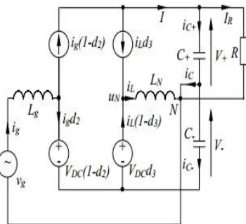
The rectifier proposed in the preliminary version of this paper [19] is investigated further in this paper. It consists of one rectification leg and one neutral leg, as shown in Figure 1. The rectifier can be formed by adding two active switches into a conventional half-bridge PWM rectifier by putting a neutral leg consisting of two switches across the DC bus with their midpoint connected to the midpoint of the split capacitors through an inductor. The neutral leg is actually a typical DC/DC converter, which has been widely adopted in industry. In particular, the neutral leg has been applied to three-phase four-wire power inverters as reported in [1], [20], [21], [22]. According to the analysis made in [1], the neutral leg is a stable system although the inductor is coupled with the split capacitors.
Fig.1. the single-phase rectifier under investigation.
It is well known that bulky electrolytic capacitors are often needed for single-phase rectifiers to smooth the second order voltage ripples on the DC bus. However, the reliability, volume and weight of electrolytic capacitors could be a serious problem for high-reliability, volume-critical and weight-critical applications [6], [7], [8]. As a result, in order to enhance the reliability and power density of rectifiers, it is highly desirable to reduce the usage of capacitors so that highly reliable capacitors like film capacitors could be used to replace electrolytic capacitors.
2.2 REDUCTION OF THE BULKY DC-BUS CAPACITORS
In order to clearly show how to significantly reduce the DC-bus capacitors, there is a need to analyse the relationship between the ripple energy and the required capacitors for the investigated rectifier. For this purpose, an average circuit model is built up at first.
It is assumed that the DC-bus voltage of the rectifier is
= +
Where V+ and V− are the voltages across the split capacitors C+ and C− with respect to the neutral point N and the negative point of the DC bus, respectively.
Suppose that the grid current is
= sin( )
And the grid voltage is
Fig. 2. The average circuit model of the rectifier shown in Figure 1.
In which Vg and Ig are the peak values of the grid voltage and current, respectively, and ω is the angular line frequency.
According to the average circuit model of the rectifier shown in Figure 2, the capacitor currents can be found as
= (1−d )− − d
=− d + (1− )
And the neutral current iL can be found as
= − + +
In order to obtain the unity power factor, the two switches Q1 and Q2 can be operated complementarily to track the reference of the grid current, which is in phase with the grid voltage. Since the switching frequency is much higher than the line frequency, the duty cycle of Switch Q2 can be calculated in the average sense as
= − sin
to maintain the bus voltage VDC,. Normally, Switches Q3 and Q4 are operated complementarily to split the
DC-bus voltage VDC into V+ and V− . The duty cycle of Switch Q3 can be calculated as
=
Because the neutral leg is operated as a DC/DC buck converter. Because of the power balance between the AC and DC
sides (ignoring the power losses), there is
2 =
And the load current is
= 2
Which is also the DC component of current I. (4) can then be re-written as
= sin( ) + sin − −
Similarly, (5) can be re-written as
=− sin( ) − sin + −
2 cos 2 + 2
1 +
As is well known, no DC currents could pass through capacitors. As a result, iL should have a DC component so that iC+ and iC− do not have any DC component. It can be found out from (10) and (11) that the DC component of iL is
− =−
2
i.e., the same value as the load current. If the neutral current iL is controlled to provide the DC
component only, that is
=−
Then the capacitor currents are
= −
2 cos 2
And
=− −
2 cos 2
In addition to the same second-order ripple current flowing through the split capacitors, the grid current ig is split between iC+ and iC− because in this case
+ (− ) =
Which could lead to high voltage ripples and hence bulky electrolytic capacitors are needed. In order to reduce the voltage ripples, the current flowing through the capacitors should be regulated differently. For this reason, a different control strategy is proposed in the next subsection.
2.3. Reduction of DC-bus Capacitance
The idea is to push the current components of iC+ in (10) through the neutral leg instead of through the upper split capacitor so that iC+ does not contain any fundamental or second order ripple currents. That is to make iC+ = 0, ignoring the switching ripples. Hence, according to (10), the current iL should be controlled to satisfy
= −
2 cos 2 −2
On the other hand, iL should also satisfy (6). Hence, in this case, the current flowing through the lower split capacitor
should be
=−
2 cos 2
III EXPERIMENTAL VALIDATION
In order to validate the design and operation of the rectifier, experiments were conducted on a test rig in the lab. The test system consists of the investigated rectifier and its control circuit, which was constructed based on TMS320F28335 DSP. The main parameters of the test system are the same as the ones in the design example of Section V as summarized in Table I. The system parameters like the inductor Lg and the switching frequency are selected according to the test rig and the available components in the lab and hence are no optimized for performance.
A. Steady-state Performance
1) The grid current ig and the DC voltages V+ and V− :
The system steady-state performance with V+∗ = 200 V is given in Figure 5(a)-(d) for V−∗max = 600, V−*
max = 650, V*−max = 700 and V−*max = 750, respectively. It is clear that the DC output voltage V+ is always maintained around its reference 200 V while the ripple voltage of V− varies from 337 V to 431 V depending on the maximum voltages of V− . Importantly, the voltage ripples of the voltage V+ are only about 5 V when V*−max = 700 V and 750 V. As a result, nearly all the ripple power is now stored on the lower capacitor C− instead of both C+ and C− over a wide range of V−. It is worth again pointing out that only two 5 µF are used in the given system. The reduction of capacitors and ripples on the output V+ has been achieved at the same time.
In order to clearly illustrate the relationship between the voltage ripples and the average voltage on the capacitor C− , the steady-state performance to reduce the ripple voltage under different average voltage of V− is shown in Figure 6. It can be clearly seen that the ripples of V+ were kept around 5 V over a wide range of V− while the ripples of V− are much larger, ranging from 337 V to 431 V. Furthermore, the ripples of V− decreased along with the increase of its average voltage. The obtained experimental results nicely match the condition (21) with
△V− = 185000 V− ave over a wide range of V−ave as long as the boost operation of the rectifier is successful. Here, the number 185000 was found via curve fitting.
Fig.2. Grid voltage vg, grid current ig and DC voltages V+ and V− with V*+ = 200 V: (a) when V−*max = 600 V, (b) when V−*max = 650 V, (c) when V*− max = 700 V and (d) when V−*max = 750V.
Fig.4. Deteriorated system performance with V+* = 200 V when V*− max = 500 V.
V− now consists of a noticeable fundamental component. The experimental data of Figures 5(c) and 8 were processed in MATLAB/SIMULINK to extract the fundamental component and indeed the fundamental component increased from 2 V to 15 V when the resonant controller was disabled.
3.1 The DC-bus current and the capacitor currents:
As mentioned above, the reduction of the voltage ripples is achieved by controlling the AC component i of the DC-bus current I. In order to show the system performance of the current control, the waveforms of the DC-bus current and the capacitors currents iC+ and iC− over a wide range of V− are shown in Figure 9(a)-(d). Note that a low-pass filter with a cut-off frequency of 6 kHz is applied to remove the high frequency component in the currents. It can be seen that the
Fig.7 DC-bus current i and capacitor currents iC+ and iC− over a wide range of V− ave.
Fig.8 Comparison of (a) without and (b) with the repetitive current controller for the neutral leg.
Moreover, the spectra of the DC-bus current I are shown in Figure and Figure to demonstrate the performance of reducing the second-order ripples in the current I for the cases without and with the repetitive controller, respectively. It is obvious that the second-order harmonic component, i.e. 100 Hz, in the current I is significantly reduced when the repetitive controller is enabled. Most of the 100 Hz component is diverted to the neutral leg from the output capacitor. Due to the diverted 100 Hz current, both the ripples of the output voltage V+ and DC-bus current I are considerably reduced as shown in Figure.
Fig.9 System start-up (V+* = 200 V and V−* = 700 V).
B. Transient Performance 1) System start-up:
In order to demonstrate the transient response of the proposed system, the results during the system start-up are shown in Figure 12. The grid current first increased to charge the capacitors and then the current was maintained well back to its steady-state value after the DC output voltage was settled. The system start-up took about 200 ms, which is only about 10 cycles.
2) Change of the voltage reference:
When the reference of the voltage V+ was changed from 200 V to 300 V, the results are shown in Figure 13. The voltage V+ was smoothly increased from 200 V to 300 V without any spikes. It is worth highlighting that the ripple level of the output voltage V+ is always small during the transient period. However, the ripples of the voltage V− became larger in order to tackle the increased ripple power caused by the increased voltage reference (and the power). This transient response took about 2 s, which is limited by the allowable maximum neutral current of the experimental system, and could be made much faster if the allowable maximum neutral current is increased. For the test rig, the neutral current is limited by the neutral inductor, which would be saturated if the neutral current exceeds about 5 A. 3) Hold-up time:
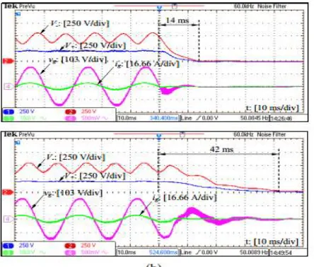
Although the DC-bus capacitors are designed for systems without hold-time requirement, it is still interesting to see how the proposed rectifier responds to a sudden AC power outage. Here, two experiments were conducted in order to show the system performance regarding to the hold-up time under different capacitors. In order for a fair comparison, only the capacitor C+ was changed while the other system parameters were kept unchanged. With C+ = 5µF, the time for the voltage V+ decreased from 200 V to 0 V is about 14 ms as shown in Figure 14(a). Of course, this time is too short for systems with hold-up requirement. A simple way to increase this time is to use a larger capacitor. The experimental result with a larger capacitor (C+ = 100 µF) is shown in Figure 14(b). Indeed, the voltage V+ was decreased at a much slower pace, which took about 42 ms for the voltage V+ to decrease from 200 V to 0 V. Since the main focus of this paper is not about the hold-up time, no further mathematical analysis is made. Interested readers are referred to [17] to see how to design capacitors for single-phase rectifiers with holdup time requirement.
C. System Performance with a Switching Load
Fig.12 System performance with a buck DC/DC converter and a resistor as the load of the rectifier.
Apart from resistive loads, rectifiers often have switching devices connected as loads. Such switching devices can in clude DC/DC converters and DC/AC converters. In order to validate this, a buck DC/DC converter shown in Figure 15(a) was built as the switching load and its output voltage Vb is regulated to be around 48 V while its input voltage V+ is 200 V and the load Rb is 20 Ω. Note that a 470 Ω resistor is also connected across the voltage V+, which means the equivalent load of the rectifier is a combination of resistive and switching loads. As shown in Figure 15(b), the voltage V+ (200 V) is levelled down to the voltage Vb (48 V) and the ripples of the voltage V+ are again kept to be very low. As a result, the proposed rectifier can indeed work well with both resistive and switching loads.
IV. CONCLUSION
This paper has addressed a big issue for single-phase rectifiers, which is to reduce DC-bus capacitors. It has been demonstrated that the required usage of DC-bus capacitors can be significantly reduced while maintaining low output voltage ripples by advanced control strategies. As a result, highly-reliable film capacitors can be used to replace bulky electrolytic capacitors. The elimination of DC-bus electrolytic capacitors is achieved by the neutral leg of the rectifier without adding any other power components. To be more precise, all the ripple energy is diverted from the upper (output) capacitor to the lower capacitor through the neutral leg so that the upper capacitor can be reduced a lot. At the same time, the voltage across the lower capacitor is designed to have large ripples as it is not supplied to any loads. In this case, both capacitors can be reduced to a level that film capacitors are cost effective to be used.
REFERENCES
1. Q.-C. Zhong and T. Hornik, Control of Power Inverters in Renewable Energy and Smart Grid Integration. Wiley-IEEE Press, 2013.
2. D. Dong, F. Luo, D. Boroyevich, and P. Mattavelli, “Leakage current reduction in a single-phase bidirectional AC–DC full-bridge inverter,” IEEE Trans. Power Electron., vol. 27, no. 10, pp. 4281–4291, 2012.
3. D. Dong, T. Thacker, I. Cvetkovic, R. Burgos, D. Boroyevich, F. Wang, and G. Skutt, “Modes of operation and system-level control of single phase bidirectional PWM converter for micro grid systems,” IEEE Transactions on Smart Grid, vol. 3, no. 1, pp. 93–104, 2012.
4. H. Wen, W. Xiao, X. Wen, and P. Armstrong, “Analysis and evaluation of DC-link capacitors for high-power-density electric vehicle drive systems,” IEEE Trans. Veh. Technol., vol. 61, no. 7, pp. 2950–2964, Sept 2012.
5. R. Wang, F. Wang, D. Boroyevich, R. Burgos, R. Lai, P. Ning, and K. Rajashekara, “A high power density single-phase PWM rectifier with active ripple energy storage,” IEEE Trans. Power Electron., vol. 26, no. 5, pp. 1430–1443, May 2011.
6. J. Stevens, J. Shaffer, and J. Vandenham, “The service life of large aluminum electrolytic capacitors: effects of construction and application,” IEEE Trans. Ind. Appl., vol. 38, no. 5, pp. 1441–1446, 2002.
7. L. Han and N. Narendran, “An accelerated test method for predicting the useful life of an LED driver,” IEEE Trans. Power Electron., vol. 26, no. 8, pp. 2249–2257, 2011.
8. P. Krein, R. Balog, and M. Mirjafari, “Minimum energy and capacitance requirements for single-phase inverters and rectifiers using a ripple port,” IEEE Trans. Power Electron., vol. 27, no. 11, pp. 4690–4698, Nov. 2012.
9. K. Yao, X. Ruan, X. Mao, and Z. Ye, “Reducing storage capacitor of a DCM Boost PFC converter,” IEEE Trans. Power Electron., vol. 27, no. 1, pp. 151–160, Jan. 2012.
10. O. Garcia, M. Martinez-Avial, J. Cobos, J. Uceda, J. Gonzalez, and J. Navas, “Harmonic reducer converter,” IEEE Trans. Ind. Electron., vol. 50, no. 2, pp. 322–327, 2003.
11. X. Zhang, X. Ruan, H. Kim, and C. K. Tse, “Adaptive active capacitor converter for improving stability of cascaded DC power supply system,” IEEE Trans. Power Electron., vol. 28, no. 4, pp. 1807–1816, 2013.
12. Q.-C. Zhong, W.-L. Ming, X. Cao, and M. Krstic, “Reduction of DCbus voltage ripples and capacitors for single-phase PWM-controlled rectifiers,” in Proc. IECON 2012 - 38th Annual Conf. IEEE Industrial Electronics Society, 2012, pp. 708–713.
13. S. Wang, X. Ruan, K. Yao, S.-C. Tan, Y. Yang, and Z. Ye, “A flickerfree electrolytic capacitor-less ac–dc LED driver,” IEEE Trans. Power Electron., vol. 27, no. 11, pp. 4540–4548, 2012.
14. S. H. Pini and I. Barbi, “A single-phase high-power-factor rectifier, based on a two-quadrant shunt active filter,” IEEE Trans. Power Electron., vol. 26, no. 11, pp. 3131–3143, Nov. 2011.