Copyright to IJIRSET www.ijirset.com 1841
Enhancing the features of UPnP/DLNA
stack for Home Network Device Profiles
Miss Shweta Kattimani
1, Dr. A. Sreenivasan
2,
Mr. Vivek R
3Student, Departmentof Telecommunication and Engineering, Dayanand Sagar College of Engineering and
Technology, Bangalore, Karnataka, India 1
Professor and Director, Centre for PG Studies in Engineering, Dayanand Sagar College of Engineering and
Technology, Bangalore, Karnataka, India2
Project Manager, Tata Elxsi Ltd. Bangalore, Karnataka, India3
ABSTRACT:The digital lifestyle is going through major changes. More and more people are self-creating, purchasing and
downloading digital content (videos, photos, and music) than at any time before. This explosion of digital content demands a fresh approach to consumer content storage, security, and management. The project describes about industry standards DLNA and UPnP technology. Here we enhance the features of UPnP/DLNA stack. The Proposed system gives a simple and robust connectivity among consumer electronics, intelligent appliances and PC‟s from different manufacturers.
Keywords: DLNA, UPNP, Home networking etc
I. INTRODUCTION
Nowadays Consumers began to go digital, acquiring, enjoying, and managing an ever growing volume of digital content and with that transition come a new required feature for the device manufacturers in the Consumer Electronics, Mobile Device, and Personal Computer domains that is interoperability. With development of home multimedia service technology, more and more multimedia become available to every corner of home through home network sharing. The technology has led to rapid development of multimedia, thus more devices can be added to home network to share files, and more multimedia file contents can be accessible by home network sharing. As sharable file types and devices increase, home network development will inevitably break the limitation of intranet.
The traditional multimedia content sharing mechanisms can only share multimedia content in home network, which reduces the usage options. In order for all providers to join the sharing network more easily, while not being limited to home network, many studies attempted to have standard. Two initiatives are Digital Living Network Alliance (DLNA) and Universal Plug and Play.
A. Digital living network alliances (DLNA)
The Digital Living Network Alliance (DLNA) was formed in 2003 by SONY, when several companies agreed that they would be able to provide better products to customers if their products where compatible across the branded boundaries. The DLNA provides interoperability guidelines for devices working in a home networked environment. The basic idea is that content stored at a device should be easily accessible for consumption on another device; even if the devices are developed by different device manufacturers. Another important point in DLNA is that devices is connected either through an Ethernet interface or a WIFI network instead of a device-specific interface, and installation and configuration procedures completed by the end user is to be minimal. The DLNA Home Networked Device Interoperability Guidelines were created by a unique cross-industry effort that combined the efforts of over 100 Consumer Electronics, PC and Mobile Device companies from around the world who worked together with the aim of achieving the world‟s first substantial approach to true interoperability between personal computers, consumer electronics, and mobile devices.
B. About UPnP Technology
Copyright to IJIRSET www.ijirset.com 1842
networks whether in the home, in a small business, public spaces, or attached to the Internet. It is a distributed, open networking architecture that leverages TCP/IP and Web technologies to enable seamless proximity networking in addition to control and data transfer among networked devices in the home, office, and public spaces. UPnP technology is used to make home networking simple and affordable. It is great opportunity for the industry. UPnP device and service standards have been defined and published for Internet gateways/routers, audio-video media devices, printers, scanners, climate control, lighting and wireless LAN access points, and digital security cameras, and advanced features such as security, remote user interface, and quality of service. UPnP technology can be implemented on any operating system and works with any type of physical networking media that supports IP – wired or wireless – providing maximum user and developer choices, which result in higher economic benefits for everyone.
II. DLNA Architecture
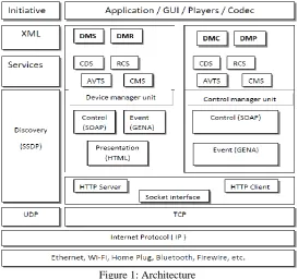
The goal of the DLNA and UPnP initiatives is to provide interoperability. To achieve interoperability between connected digital media devices in the home, a common set of building blocks based on existing standards is needed as a basis to develop the DLNA Home Networked Device Interoperability Guidelines. Table 1 in section 1 shows the specific functional components and technology ingredients that are covered in the Interoperability Guidelines. Figure 1 illustrates these functional components within the networking architecture of the Interoperability Guidelines. The Interoperability Guidelines define usage of these functional components to ensure interoperability among device classes. A brief overview of each functional component follows in the subsequent subsections.
Figure 1: Architecture
Connectivity: Three network connection technologies are incorporated in the DLNA Interoperability Guidelines:
10Base-T for wired connections, Wi-Fi (802.11) for wireless connections, and Bluetooth for wireless connections for mobile handheld devices such as cell phones and PDAs.
IP NETWORKING: UPnP makes extensive use of both the UDP and TCP protocols. Discovery is done via an HTTP
multicast over UDP and is used by devices to advertise their presence to the network and by control points to discover what devices exist on the network. Definition, control, and eventing services are delivered via HTTP over TCP.
Media Transport: Media transport defines how content travels across the home network. DLNA devices that source or
render media content across the home network must support HTTP as the baseline transport mechanism for media streaming or transfer.
Device Discovery and Control: Device discovery and control enables a device on the home network to automatically
Copyright to IJIRSET www.ijirset.com 1843
version 1.0, addresses all of these needs and simplifies device networking in the home. For this reason, UPnP Device Architecture is the device discovery and control solution for DLNA devices.
Media Management: Media management enables devices and applications to identify, manage, and distribute media
content across the home network devices. UPnP Audio/Video (AV) technology addresses all of these needs for the home network and is the media management solution for DLNA devices. The UPnP AV architecture defines the interaction model between UPnP AV devices and associated control point applications. Examples of UPnP AV devices include TVs, VCRs, DVD players, Set-Top Boxes, stereo systems, still-image cameras, and PCs. The UPnP AV architecture allows devices to support entertainment content in any format using any media transfer protocol. The UPnP AV specification defines two types of UPnP devices on the home network: UPnP AV Media Servers and UPnP AV MediaRenderers.
The specifications also define four services hosted by UPnP AV Media Servers and UPnP AV MediaRenderers. The existence of UPnP control points that interact with UPnP AV devices and services is implied.
1. Content Directory Service: Enumerates the available content.
2. Connection Manager Service: Determines how the content can be transferred from the UPnP AV MediaServer to the UPnP AV MediaRenderer devices.
3. AV Transport Service: Controls the flow of the content. 4. Rendering Control Service: Controls how the content is played.
Media Formats: Media formats describe how content is encoded and formatted for transport and rendering on the
home network. The DLNA media format model is intended to achieve a baseline for network interoperability while encouraging continued innovation in media codec technology. The DLNA media format model defines a set of mandatory and optional media format profiles for each of the three classes of media: imaging, audio, and AV. A media format profile is a set of attributes, parameters, and system and compression level details sufficient to describe the media format of a content item to enable interoperability between DLNA devices in the digital home. In addition, the DLNA media format model specifies rules about conversion between optional and mandatory formats to ensure that content can be enjoyed on all devices
III. DLNA SERVICES
In adherence to the DLNA Guidelines, Devices always implement the following 4 services:
Connection Manager Service (CMS) – This service provides information useful before or during the establishment of
a connection. The Play To controller in Windows uses this service to determine the list of media formats that the DMR can play.
AV Transport Service (AVT) – The Play To controller uses this service to control a playback session. The control
actions in a playback session include tasks like Play, Stop, Pause, or Seek.
Rendering Control Service (RCS) – The Play To controller uses this service to control the audio output in a device
(volume level and mute).
Content Directory (CDS) – Used to display a list of content stored in DMS.
Rendering Control Service (RCS)
Copyright to IJIRSET www.ijirset.com 1844
AV Transport Service (AVTS)
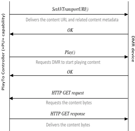
When in software, it invokes actions against the AV Transport (AVT) Service to control a media playback session. An API‟s needs to implement the following actions and the related state variables: SetAVTransportURI(), Play(), Stop(), Pause(),Seek(),SetNextAVTransportURI(),Next(),GetCurrentTransportActions(),GetPositionInfo() and GetTransportInfo(). During a Play action, DMC will establish a connection with the DMR and will use the list of actions above to control the progress of a session. Figure 3 illustrates the typical sequence of messages that DMC and the DMR exchange in order to initiate a session. As shown in Fig. 3, DMC initiates a session sending a SetAVTransportURI() action to the DMR in a network. This action carries the URI of the content item to be played. This action also carries metadata for the content item. The metadata carried in this action includes the title of the item, the content class (audio, or A/V, or images), and possibly additional URIs pointing to alternative binary representations of the content.
Upon receiving this action, the DMR changes its state from NO_MEDIA_PRESENT to STOPPED and prepares itself to play the content. At this time a DMR could start downloading the content (i.e., the DMR can send an HTTP GET request to receive the content bytes). After the DMC receives positive confirmation about SetAVTransportURI(), the DMC can send a Play() action requesting the DMR to start playing the content. Upon receiving this action, the DMR needs to render the content as soon as technically possible. Many DMRs download the content bytes only after receiving the Play() action. Fig. 3 illustrates this case where the DMR issues an HTTP GET request after the Play() action to receive the content bytes. For performance optimization, it is a better strategy if the DMR makes the request for content bytes or content segments before receiving a Play() action.
After a Pause() action, the DMR enters the PAUSED_PLAYBACK state. After a Stop() action, the DMR enters the STOPPED state. The DMR stores the current state in the TransportState state variable. DMC reads this state variable using the GetTransportInfo() action. The DMR uses the CurrentTransportActions state variable to publish the list of session control actions available in each state. The possible control actions are: play, stop, pause, and seek. DMC reads this state variable using the GetCurrentTransportActions() before sending the respective control actions. For example, a DMR that is currently playing content (PLAYING state) uses the CurrentTransportActions state variable to show the following actions available for the media resource that is currently playing:
Stop, Pause, Seek, X_DLNA_SeekTime
If the DMR moves to the STOPPED state, the DMR will show a new list of available transport actions: Play, Pause, Seek, X_DLNA_SeekTime
Besides actions and state variables, any DMR reports changes in state variables using a LastChange event. DMR devices need to implement this event as defined in UPnP/DLNA specifications. DMC subscribes to receive these events to monitor the status of several state variables in a DMR. In the source code, these entire eventing models for the AVT service are correctly implemented.
Use of the SetNextAVTransportURI()and Next() actions:
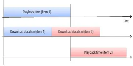
The DMC selects a list of content from the DMS and plays in a DMR one by one. For a high-quality experience, it is important to reduce the transition time from one item to the next one. For that I have implemented the feature and the explanation about this feature as given with example, the proper use of a SetNextAVTransportURI() action can effectively reduce the transition times. For example, consider the DMC that sends a 3-minute long music item. The DMR starts playing the content immediately without the need to download the entire file (i.e., progressive download). In many cases, the DMR will download the entire file before finishing playing the item.
.
Figure 2: A DMR that has access to the next URI (item 2) can start downloading the content before the moment when such content starts playing. In this way, the transition time between the end of item 1 and the beginning of item 2 can be reduced to minimal values.
Copyright to IJIRSET www.ijirset.com 1845
experience. Users do not tolerate long delays between images. Images do not have the concept of play duration. When DMC sends an image to the DMR, the DMR needs to play the image until the controller sends a new action. The new action can stop image rendering or it could trigger the rendering of a new image.
There is a way to use SetNextAVTransportURI() with images. This method is implicitly allowed by the UPnP specifications. The method works as follows:
1. The Play To controller sends the URI for image 1 2. The DMR starts playing image 1
3. The Play To controller sends the next URI (image 2) 4. The DMR continues to play image 1
5. The Play To controller sends a Next() action 6. The DMR starts playing Image 2.
P la y T o C o n tr o ll e r (+ P U + c a p a b il it y ) D M R d e v ic e SetAVTransportURI()
Delivers the content URL and related content metadata
Play()
Requests DMR to start playing content
OK
OK
HTTP GET request
HTTP GET response
Requests the content bytes
Delivers the content bytes
Figure 3: The typical protocol sequence required to play a media resource in a DMR device.
Connection Manager Service
As defined in UPnP, controllers in the network use the Connection Manager Service (CMS) to read or configure some connection-level information. From the three required CMS actions, the only one important for interoperability with DMC is:
GetProtocolInfo(): DMC uses this action to determine the list of media formats/profiles that the DMR can play. This action returns the content of the CMS SinkProtocolInfo state variable. This variable stores a comma-separated list of protocolInfo values.
Each protocolInfo value is a colon-separated list of four fields:
First field: Identifies a transport protocol. It can be http-get for HTTP-based transport, or rtsp-rtp-udp for RTP-based
transport.
Second field: It is always an asterisk.
Third field: Identifies a MIME type that can be played by a DMR.
Fourth field: See description below. DMR devices to publish protocolInfo values with four fields. Because the MIME
type is not sufficient to explain decoding capabilities, DLNA requires a fourth field that carries a string of the form:
DLNA.ORG_PN = <A Profile ID that can be decoded by the DMR> http-get:*:video/vnd.dlna.mpeg-tts:MPEG_TS_JP_T
The DMR will expose protocolInfo values that carry a Profile ID to play content that can be properly identified by the Profile ID.DMR devices publish protocolInfo values without a Profile ID for two reasons.
(1)DMR devices can play content that is not currently specified in DLNA. For example, DMR devices that can play WAV audio content expose this protocolInfo value:
Copyright to IJIRSET www.ijirset.com 1846
(2) DMR devices can play content with codec specifications beyond those defined by DLNA. For example, if a DMR device can play JPEG content with a size beyond the DLNA limit of 4000 x 4000, the DMR exposes this protocolInfo
value:
http-get:*:image/jpeg:*
If devices advertise protocolInfo values without a Profile ID, it becomes necessary to establish at least some baseline guarantees on what content types should be played for every MIME type. Users that send content to a DMR device do not want to see errors like “unsupported format” Users do not know about formats and will consider these errors as proof of poor implementation. Therefore all the formats present are supported by the source code. The media format description is written in XML format and stored in a Header file.
IV. USAGE SCENARIOS
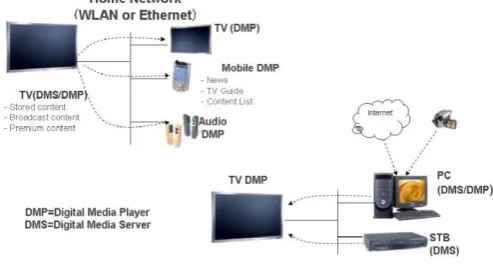
The DLNA architecture defines two types of receivers and controllers, Receivers are Digital Media Players (DMP) and Digital Media Renderers (DMR) and controllers are Digital Media controller (DMC) and Push Controller (+PU+). However many devices in practice implement both receivers and controllers. These modern DLNA Device address two key scenarios that users find attractive in home networks:
Scenario 1: The DMP scenario is important because users often grab the TV remote control to browse TV channels, or
to select radio stations, and they can also use it to play content from the home network. In this scenario users interact with the UI available in the device (TV) to bring content from the network to play in the device. This scenario is normally referred to as a two-box pull model because from a user perspective, the user pulls content available in networked servers. Here it uses Push control as controller.
Scenario 2: The DMR scenario is important because users now own a multiplicity of personal devices in the form of
smart phones and tablets. Because these devices are very personal, users know quite well how to use their functions. Also, because of proximity, users tend to use the UI on their smart phones and tablets much more frequently than the UI on other devices. Consequently, users are interested in using their portable devices to search and find content, and then push the content to nearby TVs, AVRs, or network speakers. Here it uses DMC as control unit. DMC may be mobile, tablet or remote controller.
Figure 4.1 : usage Scenarios
V. RESULTS AND CONCLUSION
The traditional multimedia content sharing mechanisms can only share multimedia content in home network, which reduces the usage options. In order for all providers to join the sharing network more easily, while not being limited to home network, many studies attempted to have standard. Two initiatives are Digital Living Network Alliance (DLNA) and Universal Plug and Play.
Copyright to IJIRSET www.ijirset.com 1847
Figure 5.1 : Notification Packets
Figure 5.2 : Subscribing resources
Figure 5.3 : Playing a Song (Packets Captured)
REFERENCES
[1] DLNA Guidelines, Volume 1: Architecture and Protocols, August 2009, http://www.dlna.org [2] DLNA Guidelines, Volume 2: Media Format Profiles, August 2009, http://www.dlna.org [3] DLNA Guidelines, Volume 3: Link Protection, http://www.dlna.org
[4] UPnP development tools for home equipment, Allegro Software Development Corporation, http://www.allegrosoft.com
[5] Intel UPnP development tools, http://www.intel.com/technology/UPnP/download.htm [6] UPnP tutorial http://www.intel.com/technology/UPnP/tutorial.htm
[7] UPnP AV 1.0 Specifications, UPnP Forum http://www.upnp.org/standardizeddcps/mediaserver.asp [8] Internet Engineering Task Force (IETF) http://www.ietf.org/internet-drafts/
[9] UPnP Forum http://www.upnp.org