Development of Control techniques for
Direct AC‐AC Matrix Converter fed Multi‐
phase Multi‐motor Drive System
Mohammed Ahmed Saleh
Electrical & Electronics Engineering College of Engineering & Science Victoria University, Melbourne, Australia
Submitted in fulfilment of the requirements of the degree of PhD
ABSTRACT
There are numerous industrial applications, such as paper mills, locomotive traction, oil and gas, mining and machine tools, which require high performance control of more than one electric motor simultaneously. When more than one electric motors are employed in an electric drive, it is called, ‘multi‐motor drive’. These multi‐motor drives are generally available in two configurations. The first one consists of a number of three‐phase voltage source inverters connected in parallel to a common DC link, each inverter feeding a three‐phase AC motor. This configuration allows independent control of all machines by means of their own three‐phase voltage source inverters (VSIs). Nevertheless, this configuration needs n number of voltage source inverters for supplying nnumber of AC machines. The second configuration comprises one inverter, which feeds multiple parallel‐connected three‐phase motors. However, the later configuration does not allow independent control of each motor and is suitable only for traction application. The power converter supplying the drive system, are conventionally, voltage source inverters. However, alternative solution could be a direct AC‐AC converter that can supply the electric drive system. Exploring this alternative solution is the subject of this thesis.
Thus for decoupled dynamic control of AC machines working in a group (multi‐motor drive) is possible by employing multi‐phase (more than three‐phase) motors, where their stator windings are connected in either series or in parallel and the combination is supplied from a single multi‐phase power converter.
This thesis explores the control techniques of multi‐phase direct AC‐AC converter for such specific series and parallel‐connected multi‐phase motor drives. The research presented here utilises additional degrees of freedom available in a multi‐phase system to control a number of machines independently. The concept is based on the fact that independent flux and torque control of any AC machine, regardless of the number of stator phases requires control of only two stator current components. This leaves the remaining current components free to control other machines within the group.
Declaration
“I, Mohammed Ahmed Saleh, declare that the PhD thesis entitled
“Development of Control techniques for Direct AC-AC Matrix
Converter fed Multi-phase Multi-motor Drive System” is no more
than 100,000 words in length including quotes and exclusive of
tables, figures, appendices, bibliography, references and
footnotes. This thesis contains no material that has been
submitted previously, in whole or in part, for the award of any
other academic degree or diploma. Except where otherwise
indicated, this thesis is my own work”.
ACKNOWLEDGEMENT
The research work presented in this thesis has been carried out under the invaluable and expert guidance of Professor Akhtar Kalam, Dr. Atif Iqbal and Prof. Haitham Abu-Rub. I consider it a privilege to have been associated with them for carrying out the research work towards my PhD degree. I have greatly benefited from their deep insight into the subject and constant support during numerous fruitful discussions. It is with a deep sense of my affection and gratitude that I wish to express my sincere thanks to them.
It is my duty to thanks the Head of the Departments, Department of Electrical Engineering, Qatar University and Department of Electrical & Computer Engineering, Texas A&M University at Qatar for their help in completing the experimental work at their laboratory.
My sincere thanks are due to Mr. SK. Moin Ahmed, Research Associate, Department of Electrical & Computer Engineering, Texas A&M University at Qatar, Qatar, for his endless support in commissioning the experimental set up used in this work.
I must also acknowledge here the fruitful discussions that I had time and again with my colleagues, Mr. Moidu Thavot, Mr. Khaleequr Rahman and Mr. Ahmad Anad of Qatar University, Doha, Qatar.
I also sincerely thanks Qatar Foundation for providing fund for the research work through the NPRP 4-152-02-053.
I would like to thank my parents, my wife’s parents and my relatives for their moral support for pursuing this work. Without their constant assurances and assistance, completion of this project would have not been possible.
List of Publications
1. Iqbal, A., Payami, S., Saleh. M., Ahmad, A.A., Moinuddin, S., (2013), “Five-phase AC/DC/AC converter with PWM rectifier”, Australian journal of Electrical & Electronics Engineering (Accepted).
2. Saleh, M,Iqbal, A., Ahmed, Sk. M., Abu-Rub. H., Kalam, A., (2013) “Direct Duty ratio based PWM control of a five-phase Matrix Converter supplying five-phase two-motor drive system”, Australian Journal of Electrical & Electronics Engg., vol. 9, issue 3, pp. 283-293, Feb. 2013
3. Ahmed, SK.M., Iqbal, A., Abu-Rub, H., Rodriguez, J., Saleh, M., (2011), “Simple carrier-based PWM technique for a three to nine-phase Matrix Converter”, IEEE Trans. On Ind. Elect., vol. 58, no. 11, pp. 5014-5023, Nov. 2011.
4. Iqbal, A., Saleh, M., Ahmed, Sk. M., Abu-Rub. H., Kalam, A., (2013) “Simple carrier-based PWM technique for a three to quasi six-phase Matrix Converter”, Australian Journal of Electrical & Electronics Engg., vol. 9, issue 3, pp. 295-304, Feb. 2013. 5. Ahmed, M. SK, Iqbal A., Abu-Rub, H., Saleh, M., Kalam. A., (2013), “Vector Control
of a Five-phase induction motor supplied by a Non-square 3X5 phase Matrix Converter”, Australian Journal of Electrical Engineering, vol. 10, no. 1, March 2013, pp. 55-63.
6. Saleh, M., Iqbal, A., Thavot, M., Kalam, A., (2013), “Modeling of seven-phase series-connected three-motor drive system”, 7th IEEE GCC COnf., Doha, Qatar, Nov. 2013 (review).
7. Saleh, M., Khan, M.A., Iqbal, A., Moin, SK., Kalam, A., (2013) “Three to seven phase Matrix Converter supplied seven-phase three-motor drive”, Journal of Innovation in Electronics and Communication, vol. 2, Issue 3, pp. 6-13. July-Dec. 2013.
8. Ahmad, R., Iqbal, A., Saleh, M., Kalam, A. (2013), “Performance Analysis of Soft Starter Based Control of Five-phase Induction Motor”, 2013 IEEE PES General Meeting, 21 - 25 July 2013, Vancouver, BC, Canada. CD-ROM paper.
9. Islam, S., Bakhs, Ilahi, Iqbal, A., Saleh, M., Kalam, A. (2013), “Stability Analysis of a Series-Connected Five-phase Induction Motor Drive System using Flux-linkage model” Paper 4604, 8th IEEE Int. conf. on Industrail electronics and applications, 19-21 June,
2013, Melbourne, Australia, CD-ROM paper.
10. Iqbal, A., Pyami, S., Saleh, M., Anad, A., Kalam, A., (2012), “Analysis of Five-phase AC/DC/AC active front end converter”, Australian Universities Power Engineering Conf (AUPEC), 26-29 Sept., Bali, Indonesia, CD-ROM paper.
11. Saleh, M.,Iqbal, A., Moin, SK., Kalam, A., (2012), “Matrix Converter based Five-phase series-connected induction motor drive”, Australian Universities Power Engineering Conf (AUPEC), 26-29 Sept., Bali, Indonesia CD-ROM paper.
Table of Contents
ABSTRACT ... i
LIST OF FIGURES ... ix
LIST OF TABLES ... xii
LIST OF ABBREVIATIONS ... xiii
LIST OF SYMBOLS ... xiv
Chapter 1 Introduction ... 1
1.1 Preliminary Remark ... 1
1.2 Power Electronic Converters ... 2
1.3 Features of Multi-phase Motor Drive ... 5
1.4 Analyzed Drive Topologies ... 6
1.5 Research Objectives ... 12
1.6 Layout of the Thesis ... 12
1.7 Novelty and Contribution of Thesis ... 14
References: ... 15
Chapter 2 Literature Review ... 17
2.1 Introduction ... 17
2.2 Multi-phase Motor Drive Systems ... 18
2.3 Three-phase input and three-phase output Matrix Converter ... 22
2.4 Multi-phase Matrix Converter ... 23
2.5 Summary ... 28
References: ... 29
Chapter 3 Over-View of Modelling and Control of three-phase by three-phase Matrix-Converter... 33
3.1 Introduction ... 33
3.2 Control Algorithms for matrix converter ... 33
3.3 MODULATION DUTY CYCLE MATRIXAPPROACH ... 34
A. Alesina-Venturini 1981 (AV method) ... 36
B. Alesina-Venturini 1989 (Optimum AV method) ... 37
A. SVM Technique ... 38
3.7 Carrier-Based PWM Approach ... 44
A. Carrier Based Control Strategy ... 44
B. Application of Offset Duty Ratios ... 45
3.8 Direct Duty Ratio Based PWM approach ... 47
3.9 Summary ... 52
References: ... 52
Chapter 4 Modelling of Multi-phase Multi-motor Drive System ... 54
4.1 Introduction ... 54
4.2 Modelling of five-phase series-connected two-motor drives ... 56
A. Modelling of series-connected five-phase two-motor drive ... 56
4.2b Model in the Rotating Reference Frame ... 60
4.2c Model in the stationary reference frame ... 63
4.2d Simulation Results ... 65
4.3 Modeling of a Six-phase Series-connected Two-motor Drive System ... 66
4.3a Phase Variable Model ... 67
4.3b Model in the Rotating reference frame ... 70
4.3c Transformation of the model into the stationary common reference frame ... 72
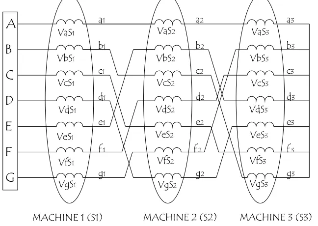
4.4 Modelling of A Seven-Phase Series-connected Three-Motor Drive System ... 74
4.4a Phase Variable Model ... 76
4.4b Model in the rotating reference frame ... 83
4.4 c Transformation of model in to the stationary common reference frame ... 91
Torque equation of the machine become ... 93
4.4d Simulation Result ... 95
4.5 Summary ... 101
References ... 101
Chapter 5 Space Vector Modelling of Multi-phase Matrix Converter ... 104
5.1 Introduction ... 104
5.2 Space Vector Model of a Three-phase to Five-phase Matrix Converter ... 104
5.3 Space Vector Model of Three-phase to Six-phase Direct Matrix Converter ... 127
5.4 Space Vector Model of Three-phase to Seven-phase Direct Matrix Converter ... 136
5.5 Summary ... 144
References: ... 145
6.1 Introduction ... 146
6.2 Generalized Carrier-based PWM Techniques for three-to N-phase ... 147
6.2a Application of offset duty ratios ... 150
6.2b Without Common Mode Voltage Addition ... 152
6.2.c With Common Mode Voltage Addition ... 152
6.2d Output Side over Modulation ... 153
6.2e Modulator Gain... 153
6.3.1 Carrier Based PWM Technique for a Three-to-Five Phase Matrix Converter .... 153
6.3a Three-To-Five Phase Matrix Converter ... 154
6.3b Simulation Results ... 156
6.3.2 Career Based PWM Technique for a Three-to-Five Phase Matrix Converter for Supplying Five-phase Two-motor Drives ... 157
6.4a Five-Phase Two-Motor Drive System ... 158
6.4b Carrier Based PWM Technique for a two motor system ... 160
6.4c Simulation Results for RL Load ... 162
6.4d Simulation Results for Motor Load ... 166
6.5 Carrier Based PWM Technique for a Three-to-Six Phase Matrix Converter ... 170
6.5a Three-to-Six Phase Matrix Converter system ... 171
6.5b Application of Offset Duty Ratio ... 172
6.5c With Harmonic Injection ... 173
6.5d Output Voltage Magnitude ... 175
6.5e Simulation Results ... 175
6.6 Carrier Based PWM Technique for a Three-to-Six Phase Matrix Converter for Supplying Six-phase Two-motor Drives ... 177
6.6a Six-Phase Series-Connected Two-Motor Drive Configuration ... 178
6.6b Carrier-Based PWM Technique For Six-Phase Two-Motor Drive ... 179
6.6c Application of Offset Duty Ratio... 180
6.6d Simulation Results ... 182
6.7 Carrier Based PWM Technique Strategies for a Three-to-Seven Phase Matrix Converter ... 186
6.7a Application of Offset Duty Ratio... 187
6.7b Without Common-mode voltage addition ... 189
6.7b With Common mode voltage Addition ... 189
6.7c Simulation Results ... 190
6.8 Seven-Phase Series Connected Three-Motor Drive System ... 193
6.8a Carrier-Based Pulse Width Modulation Technique ... 194
6.8b Simulation Results ... 197
6.8c Independent Control at Identical Frequencies ... 198
6.8d Independent Control at Three Different Frequencies ... 201
6.9b Experimental Investigation of two motor supply ... 211
6.9c Experimental investigation on 3x6 phase Matrix Converter ... 212
6.10 Summary ... 215
References ... 215
Chapter 7 Direct Duty Ratio Based Pulse Width Modulation of Multi-phase Matrix Converter ... 217
7.1 Introduction ... 217
7.2 Direct Duty Ratio based PWM Technique for a Three-phase to n-phase Matrix Converter for Single-motor drive system ... 218
Case-I: ... 218
7.3 Direct Duty Ratio Based PWM for 3-phase to 5-phase Matrix Converter ... 223
7.4 Simulation Results for Five-phase Single-motor Drive ... 226
7.4 DDPWM of three-to-fivephase Matrix Converters for five-phase two-motor drive 237 7.5 Simulation Results for Two-motor drive system ... 240
7.7 Summary ... 247
References ... 247
Chapter 8 Conclusions and Future Work ... 248
8.1 Conclusions ... 248
LIST OF FIGURES
Fig. 1.1 General block diagram of a Variable speed drive 2 Fig. 1.2. Possible discrete implementations of a bi-directional switch. 3
Fig. 1.3. Three-phase multi-motor drive system. 7
Fig. 1.4a. Five-phase series-connected two-motor drive structure. 9 Fig. 1.5. Outlay of a three-phase to n-phase direct Matrix Converter. 10 Fig. 2.1. Power Circuit topology of Three-phase to k-phase Matrix Converter. 24 Fig. 2.2. Single-sided Matrix Converter with unidirectional power switches as shown in
reference [2.58]. 27
Fig. 2.3. Indirect Matrix Converter with rectifier and inversion stage as shown in reference
[2.58]. 27 Fig. 3.1. Three phase (input) to single phase (output) basic connection. 34
Fig. 3.2. General topology of three phase to three phase Matrix Converter. 35 Fig. 3.3. Double-sided switching pattern in a cycle period Tp. 37 Fig. 3.4. Direction of the output line-to neutral voltage vectors generated by the active
configurations. 40 Fig. 3.5. Double-sided switching pattern in a cycle period Tp [3.7]. 44
Fig. 3.6. Modified offset duty ratios for all input phases. 46 Fig. 3.7. Output and Switching pattern for kth phase in the Case I. 50 Fig. 3.8. Output and Switching pattern for kth phase in the Case II. 52 Fig. 4.1. Five-phase series-connected two-motor drive structure. 56 Fig. 4.2. Response of Five-phase Two-motor drive supplied by ideal voltage source. 66 Fig. 4.3. Connection diagram for series connection of a six-phase and a three-phase machine.
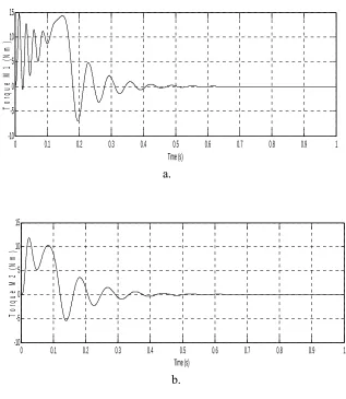
67 Fig. 4.4. Response of Six-phase Two-motor drive supplied by ideal voltage source. 74 Fig. 4.5. Seven Phase Series-Connected Three-Motor system. 75 Fig. 4.6. Response of Seven-phase Three-motor drive supplied by ideal voltage source. 97 Fig. 4.7, Torque and speed characteristics of Machine 1 97 Fig. 4.8. Torque and Speed characteristics of Machine 2. 98 Fig. 4.9. Speed and Torque Characteristics of Machine 3. 98
Fig. 4.10. Current ‘Iα-Iβ’. 98
Fig. 4.11. Current ‘Ix1-Iy1’. 99
Fig. 4.12. Source current ‘Ix2-Iy2’. 99
Fig. 4.13. Spectrum of source phase ‘a’ voltage. 99
Fig. 4.14. Spectrum of source voltage Vα. 100
Fig. 4.15. Spectrum of source voltage Vx1. 100
Fig. 4.16. Spectrum of source voltage Vx2. 100
Fig. 5.1. Basic topology of a three-phase to five-phase Matrix Converter. 105
Fig. 5.2. Switching states of Group-1. 108
Fig. 5.3. Switching states of Group-2 [4,1,0]. 110
Fig. 5.5. Output Voltage space vectors corresponding to the permitted switching
combinations. 118
Fig. 5.6. Output large length voltage space vectors. 119
Fig. 5.7. Output medium length voltage space vectors. 122
Fig. 5.8. Output small length voltage space vectors. 124
Fig. 5.9. Three-six phase direct Matrix Converter. 127
Fig. 5.10. Three-phase to six-phase DMC outpour voltage (Vdq). 134 Fig. 5.11. Three-phase to seven-phase direct Matrix Converter. 136
Fig. 5.12. Adjacent line space vectors in d-q plane. 141
Fig. 5.13. Adjacent Line voltage space vectors in x1-y1 plane. 142 Fig. 5.14. Adjacent Line voltage space vectors in x2-y2 plane. 143 Fig. 5.15. Three phase source current for 3-7 phase MC. 144 Fig. 6.1. Power circuit topology of 3xN-phase Matrix Converter. 147 Fig. 6.2. Power Circuit topology of three-phase to five-phase Matrix Converter. 154 Fig. 6.3. Input side waveforms of 3 to 5-phase Matrix Converter: (a) Input voltage and
current (b) Spectrum Input current. 156
Fig. 6.4. Output side waveforms of 3 to 5-phase Matrix Converter: (a) Five-phase filtered output phase voltages (b) Spectrum output voltage. 157 Fig. 6.5. Five-phase series-connected two-motor drive structure. 159 Fig. 6.6. Five-phase parallel-connected two-motor drive structure. 159
Fig. 6.7. Gate signal generation for output phase A. 162
Fig. 6.8. Block diagram of Carrier-based PWM for two frequency output. 162 Fig. 6.9. Input side waveforms of 3 to 5-phase Matrix Converter: upper trace. 163 Fig. 6.10. Input voltage and current, bottom trace, Spectrum Input current. 164
Fig. 6.11. Output filtered five-phase voltages. 164
Fig. 6.12. Spectrum of output voltages; phase ‘A’. 165
Fig. 6.13. Spectrum of output voltages; α-axis voltage. 165 Fig. 6.14. Spectrum of output voltages; x-axis voltage. 166 Fig. 6.15. Response of two-motor drive, a. Speeds, b. torques, c. phase ‘a’ current from
Matrix Converter. 168
Fig. 6.16. Source side voltage and current, voltage is reduced to 150 times. 168 Fig. 6.17i. Matrix Converter output current and voltage time domain and frequency domain
waveform. 169 Fig. 6.18. Power Circuit topology of Three-phase to quasi six-phase Matrix Converter. 170
Fig. 6.19. Stator winding displacement of a quasi or double star six-phase ac machine. 171 Fig. 6.20. Modified offset duty ratios for all input phases. 173 Fig. 6.21. Common mode added reference for output phases. 174
Fig. 6.22. Duty ratio for output phase A. 174
Fig. 6.31. Spectrum of output voltages; a. phase ‘A’, b. α-axis voltage and c. x-axis voltage. 186 Fig. 6.41. Spectrum of output voltages; a. phase ‘A’, b. α-axis voltage c. x1-axis voltage, d.
x2-axis voltage. 200
Fig. 6.43. Output waveforms, filtered output phase ‘a’ voltage. 203
Fig. 7.2. Output and Switching pattern for nth phase in the Case II. 222 Fig. 7.3. General Implementation diagram of 3 to k phase Matrix Converter. 223
Fig. 7.4. Output pattern of phase ‘a’. 224
Fig. 7.5. Output pattern of Phase ‘b’. 224
Fig. 7.6. Output pattern of phase ‘c’. 225
Fig. 7.7. Output pattern of phase ‘d’. 225
Fig. 7.8. Output pattern of phase ‘e’. 225
Fig. 7.9. DPWM implementation block without harmonic injection. 227 Fig. 7.10. Input side waveforms of 3 to 5-phase Matrix Converter: a. Input voltage and input
filtered current b. Spectrum input current, c. Input phase current locus. 229 Fig. 7.11. Output side waveforms of 3 to 5-phase Matrix Converter: a. Five-phase output
filtered phase voltages b. Spectrum output filtered voltage, c. locus of α-β axis output voltage, d. locus of x-y axis output voltage, and e. output voltage and current phase ‘a’.
231 Fig. 7.12. Input and output voltage waveforms for a 3 to 5-phase Matrix Converter. 231 Fig. 7.13. Modulation Implementation block using harmonic injection. 233 Fig. 7.14. Input side waveforms of 3 to 5-phase Matrix Converter: a. Input voltage and
current, b. Spectrum input current, c. Input phase current locus. 234 Fig. 7.15. Output waveforms of 3 to 5-phase Matrix Converter: a. Five-phase output filtered
voltages, b. Spectrum output voltage, c. locus of α-β axis output voltage, d. locus of x-y
axis output voltage and e. Phase ‘a’ voltage and current. 236 Fig. 7.16. Input and output voltage waveforms for a 3 to 5-phase Matrix Converter with
harmonic injection. 236
Fig. 7.17 General Implementation diagram of 3 to 5phase Matrix Converter. 238 Fig. 7.18. General Block diagram of PWM for two frequency output. 239 Fig. 7.19. The input side waveforms; a. source side voltage and current for phase ‘a’, b.
source side three-phase currents, c. converter side three-phase currents. 242 Fig. 7.20. The output side waveform; a. Phase, adjacent and non-adjacent voltages, b. filtered
output phase voltages, c. five-phase inverter currents. 243
Fig. 7.21. The transformed voltage of the output phase voltages: a. and b. Vxy. 244
Fig. 7.22. Time domain and frequency domain waveforms: a. Phase ‘a’ voltage, b. voltage
and c. Vx voltage. 245
Fig. 7.23. Experimental results: tope trace, phase Voltage, middle trace adjacent line Voltage, and the bottom trace, non-adjacent line Voltage (y-axis: 200V/div, x-axis: 10 msec/div).
LIST OF TABLES
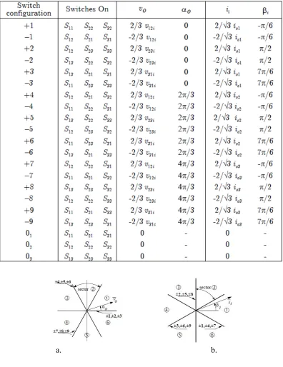
Table 2.1. Reduction in stator copper loss vs phase number of machine. 19 Table 3.1. SWITCHING CONFIGURATIONS USED IN THE SVM ALGORITHM. 39 Table 3.2. Selection of the switching configurations for each combination of output voltage
and input current sectors. 40
Table 4.1. Connectivity matrixfor five-phase two motor drive as shown in reference [4.3]. 56
Table 4.2. Connectivity Matrix. 76
Table 5.1. Large length vectors. 120
Table 5.2. Medium length vectors 122
Table 5.3. Small space voltage vectors. 125
Table 5.4. Three to Six phase output voltage and input current. 130 Table 5.5. The 189 vectors of table.5.4 are distributed as: 134
LIST OF ABBREVIATIONS
VSI Voltage Source Inverter CSI Current Source Inverter PWM Pulse Width Modulation
MC Matrix Converter
DDPWM Direct Duty Ratio Pulse Width Modulation
DC Direct current
AC Alternating Current THD Total Harmonic Distortion
DSP Digital Signal Processors
FPGA Field Programmable Gate Arrays
PC Personal Computer
HVDC High Voltage DC FFT Fast Fourier Transform
RMS Root Mean Square
IGBT Insulated Gate Bi-polar Transistor
LC Inductor Capacitor
WTHD Weighted Total Harmonic Distortion DMC Direct Matrix Converter
LIST OF SYMBOLS
V Voltage Volt (V)
I Current Ampere (A)
R Resistance Ohms (Ω)
α0 Output current space vector -
β0 Output voltage space vector -
αi Input current space vector -
βi Input voltage space vector -
ω Angular Velocity rad/sec
aa
L Self Inductance between phase a and a Henry (H)
ab
L Self Inductance between phase a and b Henry (H)
M Mutual inductance Henry (H)
Chapter 1
Introduction
1.1 Preliminary Remark
Variable speed motor drive system is required in numerous industrial applications as they offer significant advantages compared to a fixed speed drive system. The major advantages include higher efficiency, better power factor, reduced thermal loading and thus reduced overall operational costs. Three-phase motor drives are traditionally used in industrial drives due to readily available three-phase supply and off-the-shelf motor availability. Power electronic converters are used as interface between three-phase grid supply and the driving motor. The power converter has no limitation in number of legs being used and thus there is no restriction in the number of phases of the converters. With the advancement in power semiconductor technology this additional degree of freedom in power electronic converter is now exploited by developing multi-phase supply options. Hence multi-phase (more than three-phase) electric drives have attracted much attention in recent years due to some inherent advantages that they offer compared to their three-phase counterpart such as lower motor torque pulsation, less DC link current harmonics, higher redundancy and hence better fault tolerant characteristics and lower per phase converter ratings etc. The major applications of multi-phase drives are assumed in safety critical applications such as ship propulsion, ‘more electric aircraft’ applications, electric and hybrid-electric vehicles, traction, mining, oil & gas and in general purpose applications in high power range as presented in reference [1.1] - [1.4].
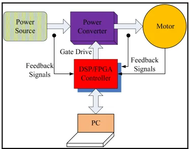
A block diagram of a variable frequency drive system is shown in Fig. 1.1 The major components of a variable drive system are: power source (grid supply), power converter for power processing, controller that can be digital signal processor/micro-controller/field programmable gate arrays, electric motor, sensors (voltage, current and speed) for feedback signals. The controller can be programmed using PC.
The power supply to a variable speed drive system is obtained from power electronic converter that is capable of providing variable voltage and variable frequency. There are four types of power electronic converters:
ii) AC/DC/AC converter with PWM rectifier also called back-to-back converter, iii) AC/AC converter called cyclo converter, and
iv) AC/AC converter called Matrix Converter.
This thesis developed control techniques for direct AC/AC converter, i.e. a Matrix Converter.
Fig. 1.1 General block diagram of a variable speed drive
1.2 Power Electronic Converters
i) AC Voltage Regulator ii) Cyclo converters
iii) AC-DC-AC converter with diode based rectifier called an inverter
iv) AC-DC-AC converter with active rectifier or PWM rectifier called back-to-back converter
v) AC-AC converter called Matrix Converter.
AC voltage regulators have limited use since they can only vary the voltage while the output side frequency is same as the input side frequency. The power semiconductor switching device used should have bi-directional power flow characteristics. Bi-directional switching can be obtained by connecting anti-parallel BJTs, or MOSFETs, or IGBTs. In some applications Triacs and Thyristor based voltage regulators are also used. Other ways of obtaining bi-directional power flow is shown in Fig. 1.2. This is further elaborated in Chapter 3. The output voltage in AC voltage regulator varies from 0 to input voltage magnitude. Hence the maximum voltage transfer ratio is 1.
Fig. 1.2. Possible discrete implementations of a bi-directional switch.
Cyclo converter is fully controlled direct AC-AC conversion. Both output voltage magnitude and frequency are controllable. The maximum output voltage magnitude is same as input voltage magnitude while the output frequency is limited to 33% of the input frequency. Hence the application of cyclo converter is also limited but they are used where small speed control range is needed and is mostly used in high power drive system.
rectifiers are in practice but mostly three-phase bridge type rectifiers are the most common. The output of rectifier contains ripple that can be minimized by using a filter. The output of a rectifier is used to feed inverter system through DC link capacitor. Large values of DC link capacitors are usually used to offer constant voltage to the inverter. Rectifiers are uncontrolled but the inverter is controlled using different types of pulse width modulation. AC-DC-AC converter with controlled rectifier or active rectifier called back-to-back converter is also employed where bi-directional power flow is required. The rectifier is controllable and the power factor can be controlled and can be even made unity. The source side current is sinusoidal. In case of regeneration of drive system, power can flow back to the utility grid and this is only possible when active rectifier is used. The output voltage magnitude is limited by the amount of DC link voltage and the type of PWM method employed.
Direct AC-AC converter system mostly called Matrix Converter consist of arrays of bi-directional power semiconductor switches (bi-bi-directional switches are shown in Fig. 1.2). Three-phase utility grid system is connected to the output through the matrix arrays. Each leg has three bi-directional switches and any output can be connected to any input line through the switching action of bi-directional power switches. The voltage of input side appears at the output side and the current in any phase of the load can be drawn from any phase of the utility grid. A small LC filter is connected at the source side to remove the current ripple (Which appears due to switching action). Matrix Converter has the following major advantages:
Sinusoidal input and output currents
Controllable input side power factor
No bulky DC link capacitor is needed
Bi-directional power flow.
1.3 Features of Multi-phase Motor Drive
An obvious question arises, why the thesis topic is chosen on multi-phase motor drive when three-phase drive is being successfully used in industries for decades? The simple answer lies in the inherent advantages that a multi-phase drive offers compared to their three-phase counterpart. Some of the known advantages of multi-phase motor drives are given in reference [1.1]:
a. Reducing the amplitude of torque pulsation and increasing the frequency of torque pulsation in inverter fed multi-phase drive system when inverter is operating in square wave mode. The frequency of torque pulsation is 2n*fundamental frequency, where n is the number of phases. Thus for instance in a five-phase machine the torque pulsation occurs at 10 times the fundamental frequency while in three-phase case it is 6 times the fundamental.
b. .Higher efficiency compared to the three-phase counterpart. This is attributed to the fact that the stator excitation produces a field with lower space harmonic in case of multi-phase machine when compared to three-phase machines.
c. Higher torque density in multi-phase machines compared to the three-phase machines. The reason behind this is that apart from fundamental, higher current harmonic contribute towards the torque development in concentrated winding machines. For instance in case of a five-phase machine, third harmonic along with the fundamental may be injected to enhance the torque production and similarly in case of a seven-phase machine, 3rd and 5th harmonics may be utilised. Thus in general harmonics lower than the phase number may be utilised effectively to enhance the torque production. This is a special characteristic of multi-phase machines and is not available in a three-phase machine.
case of a seven-phase machine unnoticeable change occurs even with a loss of up to two phases. This trend continues with higher phase number. Thus multi-phase machine drive is suited ideally for safety critical applications such as ship propulsion, air craft applications & defence and emergency services applications.
e. Less volume to weight ratio
f. Better noise and vibration characteristics g. Lower DC link current harmonics h. Reducing rotor current harmonics
i. Reducing current per-phase without increasing voltage per-phase. This reduction in power per-phase translates into the reduction in the rating per converter leg. Thus the series/parallel combination of power semiconductor switches may be avoided and consequently avoiding the associated static and dynamic voltage sharing problems. This is one of the driving forces behind the accelerated use of multi-phase machines in high power drive applications.
1.4 Analyzed Drive Topologies
In this thesis, multi-phase multi-motor drive system is analyzed. The focus of the research is on the development of control schemes for multi-phase Matrix Converter feeding multi-phase multi-motor drive system. When referring to multi-motor drive system, means more than one machine are controlled simultaneously either independently or under identical operational conditions. In three-phase multi-motor drive system, two topologies are possible:
i) X number of three-phase motors with independent vector control, which is fed using X number of three-phase inverters with 3X legs. Motor/inverter sets connected in parallel, with common DC link. This configuration is shown in Fig. 1.3a.
ii) X number of three-phase motors which is fed using one three-phase inverter. In this structure motors have to be identical and to operate under the same load torque with the same angular speed. This is shown in Fig. 1.3b.
Vector Feedback control
common
DC link 3-phase
PWM Machine
VSI 1
3-phase Machine
PWM 2
VSI
Vector
control Feedback
a b
Fig. 1.3. Three-phase multi-motor drive system.
Multi-phase drive system can however, offer independent control of more than one machine when supplied from a single variable voltage and variable frequency power source and field oriented control is employed as shown in reference [1.6].
This is a generalized concept where multi-phase machine’s stator can be either connected in series or in parallel while supply is given from only one power source and all the machines can be controlled independently both in transient and steady state conditions. The topologies investigated in this thesis are:
Five-phase series-connected two-motor drive system
Six-phase series-connected two-motor drive system
Seven-phase series-connected three-motor drive system.
It is important to mention here that the main purpose of the thesis is to develop pulse width modulation techniques for three-phase input and multi-phase (5-phase, 6-phase, 7-phase) output to produce appropriate fundamental frequencies. Further to note, that the developed PWM are equally applicable to series-connected drive and parallel-connected drive systems. Series-connected or parallel-connected refers to stator winding connection and rotors are independent.
It is evident from the dynamic model of multi-phase machine in given reference [1.7], that only two orthogonal current components namely d-q is responsible for torque production and rest of the components do not contribute to the torque production rather they are loss
Vector ControlControlVector
3-phase PWM
VSI
Machine 1
Machine 2 Feedback
signals Feedback signals
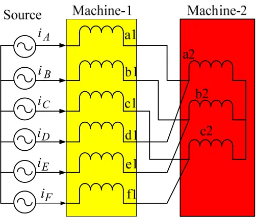
drive are shown in Fig. 1.4. These three drive system topologies are used in the present thesis for developing their control using direct AC-AC multi-phase Matrix Converter.
A
I
B
I
C
I
D
I
E
I
1
2Fig. 1.4a. Five-phase series-connected two-motor drive structure.
A
I
B
I
C
I
D I
E
I
1
2F
I
Fig. 1.4b. Six-phase series-connected two-motor drive system.
A
I
B
I
C
I
D I
E
I
1
F I
2
a
i
2
b
i
2
c i
2 d
i
2
e
i
2
2
f
i
3
a
i
3
b
i
3
c i
3 d
i
3
e
i
3
3
f
i
3
g
i 2
g
i
Since the thesis explores the Pulse Width Modulation (PWM) of AC-AC Matrix Converter for controlling multi-phase multi-motor drive system, it is important to present state-of-the-art in the PWM techniques of such converter. A review on the state-of-the-state-of-the-art in the Matrix Converter is presented in references [1.13] - [1.16]. Power circuit of a general three-phase to
n-phase Matrix Converter is shown in Fig. 1.5. The determination of appropriate PWM method for complex Matrix Converter topology especially for multi-phase output is a key issue. The restriction imposed on the PWM strategies are: the input phases must not be short circuited and the output phase should not be open circuited.
Fig. 1.5. Outlay of a three-phase to n-phase direct Matrix Converter.
The early modulation method proposed by Alesina and Venturuni [1.17] - [1.18] for three-to three-phase Matrix Converter may still be extended for multi-phase Matrix Converter topology with some modifications, but the output voltage magnitude will once again be limited to 50% of the input voltage magnitude. Thus it is not practical to use this method due to small output voltage magnitude. Similar concept is put forth in reference [1.19], where the outputs are dealt independently and PWM method is presented focusing on three-to single-phase and three-to three-single-phase Matrix Converter. This thesis describes the application of optimum control theory to N-input K-output Matrix Converters based on the transformation of actual converter topology into a suitable equivalent structure. The topologies and control properties of the most common Matrix Converters are analyzed by developing the general anti-transformation criteria.
multi-number of space vectors available. For instance in a three-to five-phase Matrix Converter total number of space vector generated are 215 = 32768, nevertheless, due to constraints
imposed by switching actions, 35 =243 vectors are useful. Following the analogy with five-phase three-level voltage source inverter, the number of space vectors that can be used to generated sinusoidal output is further limited to 93 as in reference [1.22]. Nevertheless, space vectors PWM for real time processing still poses a challenge. The output voltage magnitude with space vector PWM in a three to five-phase Matrix Converter is limited to 78.86% of the input magnitude for linear modulation range. This limit can further be raised by exploiting over-modulation region. No work has so far been reported on over-modulation of the multi-phase Matrix Converter and also this is not the subject of this thesis.
Carrier-based PWM scheme is the simplest approach for controlling a Matrix Converter. Carrier based PWM is one of the recently developed modulation strategies for the Matrix Converter in three-to three-phase topology. As in the traditional sinusoidal PWM used in voltage source inverters, it employs the carrier and reference signals. The implementation of this scheme is simpler compared to the space vector PWM by using conventional UP/DOWN counters, which are embedded in most of the single chip microcontrollers. However, the carrier signal employed in this PWM is discontinuous and thus the method is intuitively difficult to understand. In addition, increasing the limit of modulation is a trivial task. Since, offset is added in this PWM, it is not suitable for topology where input and output neutral needs connection.
Another simpler and modular modulation approach, compared to the space vector PWM was developed called ‘direct duty ratio PWM’, which offers the advantages of simpler real time implementation as shown in reference [1.25]. This approach is modular in nature and it is seen that this can be employed for any phase number or switch number of the Matrix Converter. The major advantage of this modulation scheme is that it is highly intuitive and flexible, and can be applied to any topology of the Matrix Converter as the concept is based on ‘per output phase’.
Carrier-based PWM
Direct duty ratio based PWM.
1.5 Research Objectives
The present research is based on the development of mathematical model of three-phase input and multi-phase output direct AC-AC Matrix Converter and exploring their control algorithm for the multi motor drive system. The principle set objectives of the proposed research are:
i) To investigate the current state-of-the art in multi-phase motor drive research area by carrying out comprehensive literature review from available data bases.
ii) To review the modelling procedure of a five-phase series-connected two-motor drive, a six-phase and three-phase series-connected two-motor drive and a seven-phase three-motor drive using general machine modelling approach.
iii)To review the modelling procedure of a three-phase to five-phase Matrix Converter, a three-phase to six-phase Matrix Converter and three-phase to seven-phase Matrix Converter using space vector concept.
iv) To investigate the operation of a three-phase input and five-phase output Matrix Converter for producing two independent fundamental frequency components using; i) carrier-based PWM, ii) direct duty ratio based PWM assuming series-connected/parallel-connected two motor drive system being fed using this power source.
v) To investigate the operation of a three-phase input and six-phase output Matrix Converter for producing two independent fundamental frequency components using carrier-based PWM, assuming series-connected/parallel-connected two motor drive system being fed using this power source.
vi) To investigate the operation of a three-phase input and seven-phase output Matrix Converter for producing three independent fundamental frequency components using carrier-based PWM, assuming series-connected/parallel-connected three motor drive system being fed using this power source.
1.6 Layout of the Thesis
multi-phase motor drives. An overview on the existing power electronic converter topologies is presented. A question is raised as to why at all the proposed research is looking into the multi-phase motor drives and in support a number of existing advantages are highlighted. An overview of the drive configuration investigated in the thesis is elaborated. Brief introduction to the Matrix Converter is elaborated. The objectives of the research are set and are discussed.
Chapter 2 presents literature review in the multi-phase multi-motor drive control research. At first state-of-the art in multi-phase drive system is discussed. This is followed by the description on conventional Matrix Converter topology and its control is elaborated. Finally multi-phase Matrix Converter topology is discussed along with its control and work done so far in the literature.
Chapter 3 is dedicated to the existing control technique of conventional phase to three-phase direct Matrix Converter. The control can be divided into scalar and vector control approaches. The limitation of lower output voltage is rectified by harmonic injection. Theoretical maximum limit of output voltage is achieved and elaborated.
Chapter 4 is dedicated to the modelling of a multi-phase series-connected multi-motor drive system. Three configurations are taken up for discussion: five-phase series-connected two-motor, six-phase two-motor and seven-phase three-motor. Modelling is done assuming multi-phase induction machines. Although this concept of series connection is independent of type of machines, but only one type of machine is considered to show the viability of the approach. Phase variable modelling approach is used with general assumption of sinusoidally distributed mmf. This is followed by transformation of the model in the rotational reference frame and then in the stationary reference frame. The developed model is validated using MATLAB/SIMULINK approach assuming ideal sinusoidal supply.
Chapter 5 elaborate the space vector model of multi-phase Matrix Converter. Three different topologies are discussed: three-phase to five-phase, three-phase to six-phase and three-phase to seven-phase. For n-phase input and m-phase output, the number of switching states is 2nxm and after imposing the constraints, the remaining switching states are elaborated in this chapter.
approach of carrier-based PWM is discussed in Chapter 6. At first carrier-based scheme for single-motor drive is elaborated followed by multi-phase multi-motor drive system. Five-phase single-and two-motor drive, six-Five-phase single and two-motor drive and seven-Five-phase single-and three-motor drive topologies are discussed. Simulation and experimental results are included to validate the PWM schemes.
Chapter 7 elaborate another PWM technique based on direct duty ratio calculation. This is a simple approach that is highly modular in nature since the computation is done one per-leg basis. Five-phase single-motor and two-motor drive system is discussed. Simulation and experimental results are included.
Chapter 8 is the final chapter, and provides a summary of the thesis and the salient points from each chapter. Conclusions are made as to the viability of the series-connected/parallel-connected multi-phase multi-motor drive fed using three-phase input multi-phase output direct Matrix Converter. Future research work possible related to this area is suggested and reported in this chapter.
References used in each chapter are given at the end of each chapter itself and hence no separate references chapter is given. List of publications out of this thesis is provided at the end.
1.7 Novelty and Contribution of Thesis
The major contributions of the thesis are as follows:
Development of mathematical model of multi-phase multi-motor drive system. Mathematical model of a five-phase two-motor drive and a six-phase two-motor drive is obtained from the literature and is further developed in and reported in the thesis. Mathematical model of seven-phase three-motor drive system is not reported in the literature and is developed in this thesis based on phase variable concept. The developed model is then transformed into three orthogonal planes using general transformation matrix. The mathematical model developed is verified using simulation approach. The developed mathematical model helps in developing decoupled control scheme.
References:
[1.1] E. Levi, “Multi-phase Machines for Variable speed applications” IEEE Trans. Ind. Elect., vol. 55, no. 5, May 2008, pp. 1893-1909.
[1.2] G.K. Singh “Multi-phase induction machine drive research – a survey”, Electric Power System Research, vol. 61, 2002, pp. 139-147.
[1.3] R. Bojoi, F. Farina, F. Profumo, Tenconi,“Dual three induction machine drives control-A survey”, IEEE Tran. On Ind. Appl.,vol. 126, no. 4, pp. 420-429, 2006. [1.4] E. Levi, R. Bojoi, F. Profumo, H.A. Toliyat, S. Williamson, “Multi-phase induction
motor drives-A technology status review”, IET Elect. Power Appl. Vol. 1, no. 4, pp. 489-516, July 2007.
[1.5] H. Abu-Rub, A. Iqbal, J. Guzinski, “High Performance Control of AC Drives with
MATLAB/SIMULINK Models”, Wiley, UK, 2012.
[1.6] A. Iqbal, “Modelling and control of series-connected five-phase and six-phase two-motor drives,” PhD Thesis, Liverpool John Moores University, Liverpool, UK, 2006. [1.7] E. Levi, M .Jones, S.N. Vukosavic, H.A. Toliyat, “A novel concept of a multi-phase,
multi-motor vector controlled drive system supplied from a single voltage source inverter,” IEEE Trans. on Power Electronics, vol. 19, no. 2, 2004, pp. 320-335. [1.8] E. Levi, S.N. Vukosavic, M. Jones, “Vector control schemes for series-connected
six-phase two-motor drive systems,” IEE Proc. – Electric Power Applications, vol. 152, no. 2, 2005, pp. 226-238.
[1.9] M. Jones, S.N. Vukosavic, E.Levi, A.Iqbal, “A six-phase series-connected two-motor drive with decoupled dynamic control,” IEEE Trans. on Industry Applications, vol. 41, no. 4, 2005, pp. 1056-1066.
[1.10] E. Levi, M. Jones, A. Iqbal, S.N. Vukosavic, H.A. Toliyat, “An induction machine / Syn-Rel two-motor five-phase series-connected drive,” IEEE Trans. on Energy Conversion, vol. 22, no. 2, 2007, pp. 281-289.
[1.11] E. Levi, M. Jones, S.N. Vukosavic, A. Iqbal, H.A. Toliyat, “Modelling, control and experimental investigation of a five-phase series-connected two-motor drive with single inverter supply,” IEEE Trans. on Industrial Electronics, vol. 54, no. 3, 2007, pp. 1504-1516.
[1.12] M. Jone, E. Levi, S.N. Vukosavic, H.A. Toliyat, “Independent vector control of a seven-phase three-motor drive system supplied from a single voltage source inverter”,
Proc. 34th IEEE PESC, 2003, vol. 4, pp. 1865-1870.
[1.13] P.W. Wheeler, J. Rodriguez, Jon C. Clare, L. Empringham, A. Weinstein, “Matrix Converters: A Technology Review”, IEEE Trans. On Ind. Elect. vol. 49, no. 2, April, 2002, pp. 276-288.
[1.14] P. Wheeler, L. Xu, M. Y.Lee, L. Empringham, C. Klumpner, J.Clare, “A review of multi-level Matrix Converter topologies,” Proc. IET Power Electronics, Machines and Drives Conf., York, UK, 2008, pp. 286-290.
[1.15] L. Empringham, J. Kolar, J. Rodriguez, P. W. Wheeler, J. C. Clare, "Technological issues and industrial application of Matrix Converters: A review," IEEE Trans. on Ind. Elec., 2013 (d.o.i.10.1109/TIE.2012.2216231).
[1.16] J. Rodriguez, M. Rivera, J. W. Kolar, P. W. Wheeler, "A review of control and modulation methods for Matrix Converters," IEEE Trans. On Ind. Elec., vol. 59, no. 1, pp. 58-70, 2012.
[1.18] A. Alesina, M. Venturini, “Analysis and design of optimum amplitude nine-switch direct AC-AC converters”, IEEE Trans. Power Elect. vol. PE-4, no. 1, pp. 101-112, 1989.
[1.19] P. Tenti, L. Malesani, L. Rossetto, “Optimum control of N-input K-output Matrix Converters,” IEEE Trans. on Power Electronics, vol. 7, no. 4, 1992, pp. 707-713. [1.20] D. Casadei, G. Grandi, G. Serra, A. Tani, “Space vector control of Matrix Converters
with unity power factor and sinusoidal input/output waveforms”, Proc. EPE Conf.,
vol. 7, pp. 170-175, 1993.
[1.21] L. Huber, D. Borojevic, “Space vector modulated three-phase to three-phase Matrix Converter with input power factor correction”, IEEE Trans. Ind. Appl. Vol. 31, no. 6, pp. 1234-1246, Nov./Dec. 1995.
[1.22] Sk. M. Ahmed, A. Iqbal, H. Abu-Rub, M.R. Khan, “Space vector PWM technique for a novel three-to-five phase Matrix Converter,” IEEE Energy Conversion Conf. and Exhibition, Atlanta, GA, 2010, pp. 1875-1880.
[1.23] Sk. M. Ahmed, A. Iqbal, H. Abu-rub, M.R. Khan, “Carrier based PWM technique for a novel three-to-seven phase Matrix Converter,” Int. Conf. on Electrical Machines ICEM, Rome, Italy, 2010, CD-ROM.\
[1.24] A. Iqbal, Sk.M. Ahmed, H. Abu-Rub, M.R. Khan, “Carrier based PWM technique for a novel three-to-five phase Matrix Converter,” Power Conversion and Intelligent Motion PCIM, Nuremberg, Germany, 2010, pp. 998-1003.
Chapter 2
Literature Review
2.1 Introduction
Traditionally, variable-speed electric drives are based on three-phase configuration of an electric machine and a power electronic converter. Such a situation is the relic of a bygone era, when machines were supplied from the grid. Since the power electronic converter can be viewed as an interface that decouples three-phase mains from the machine, the number of machine’s phases does not have to be limited to three in variable-speed drives as shown reference [2.1]. Nevertheless, three-phase machines are still customarily adopted for variable speed applications due to the wide off-the-shelf availability of both machines and converters. However, in all applications where a machine is not readily available, multi-phase machines (machines with more than three phases on stator) offer a number of advantages as shown in reference [2.2]. These include (but are not limited to): i) possibility of splitting the required per-phase power rating across more than three phases, thus reducing current rating of the semiconductor components (of exceptional importance in high-power and high-current applications), ii) a significant improvement in fault tolerance of the drive, since any AC machines (regardless of the number of phases) requires only two currents for independent flux and torque control of the machine (in a three-phase machine open-circuit fault in one phase means that there are not two independent currents available for control anymore; however, an n-phase machine can continue to operate with a rotating field in post-fault operation as long as no more than (n-3) phases are faulted), and, iii) a potentially better efficiency due to reduced space harmonic content of the magneto-motive force.
Although the multi-phase variable-speed drive systems have been a subject of research interest for the last 50 years, it is the last ten years that have seen an enormous growth of the quantum of knowledge in the area as presented in reference [2.1]. This has been initiated by numerous specific application areas, such as high power industrial applications, electric ship propulsion, locomotive traction, electric and hybrid electric vehicles, etc., where advantages of multi-phase systems outweigh the initial higher cost of the development.
electronic switches. Restricting the discussion of AC/AC power frequency conversion to static circuits, the available structures can be divided in “direct” and “indirect” power conversion schemes. Indirect schemes consist of two or more stages of power conversion and an intermediate DC-link stage is always present. A typical example of two stage indirect AC/DC/AC power frequency conversion is the diode-bridge rectifier-inverter structure, in which an AC power is firstly converted to a DC power (diode rectifier), and then converted back to an AC power at variable frequency (inverter). In direct conversion schemes a single stage carries out the AC/AC power frequency conversion. This is the subject of the research.
2.2 Multi-phase Motor Drive Systems
Multi-phase ac machine can be either induction or synchronous. The induction machine can be either a wound or cage type, it is the later design which has been extensively discussed in the literature. In synchronous category it can either be a permanent magnet, with field winding or reluctance type. The stator of a multi-phase can be designed with sinusoidal winding or with concentrated winding. Both machines differ in properties due to different distribution of their mmf waves. Some of the properties of multi-phase machines which are independent of their type and are highlighted in references [2.3]-[2.10].
MMF produced by stator excitation have lower space harmonics and this affect a number of characteristics of a multi-phase machine such as their efficiency and power factor.
The frequency of torque ripple in a multi-phase machine fed using a multi-phase inverter operating in square wave mode is 2n, where n being phase number, thus increasing phase number correspondingly increases the frequency of torque ripple.
Only two current components are required for the torque/flux control of an ac machine irrespective of number of phases thus the extra current components available in multi-phase machines can be utilised for other purposes.
Due to availability of large number of phases a multi-phase machine is more fault tolerant compared to their three-phase counterpart. Since only two current components are required for torque/flux control a multi-phase machine do not pose any problem in the event of occurrence of fault unless there is a loss of more than n-3
phases occurs.
The consequence of mmf with lower space harmonic in multi-phase machine is their higher efficiency and lower acoustic noise. Higher frequency of torque ripple once again put less stress on the driving load and quieter operation of the machine. Higher efficiency of multi-phase machine compared to three-multi-phase machine may be explained as follows: consider two machines of identical design with different phase numbers. If both machines have to develop same amount of torque at same speed, then they must have same rotor copper losses, same air-gap mmf and same fundamental component of stator current. The higher efficiency is attributed to lower stator copper losses. The stator copper losses will reduce with increasing phase number as given in Table [2.1].
Table 2.1. Reduction in stator copper loss vs phase number of machine.
Phase Number 5 6 9 12 15
Reduction in stator Cu. Loss 5.6% 6.7% 7.9% 8.3% 8.5%
It is important to note here that the rotor copper losses and iron losses (since air gap mmf is unchanged) will remain unchanged with the change in machine phase number. The reduction in stator copper losses is due to that fact that the stator current lower order harmonic changes. The use of higher phase number increases the pole number of the harmonic components and thus reducing their magnitude and consequently reducing the stator copper losses due to these harmonic components.
Reduction in the magnitude of torque pulsation and the increase in the frequency of torque pulsation in an inverter (operating in 180° conduction mode) fed multi-phase is their another salient feature. as in reference [2.11], it is demonstrated that the air gap field produced by qth
harmonic component of excitation current in a 2P pole machine with n balanced phases will have pole-pair numbers given by:
( 2 ) 0, 1, 2, 3,...
P q kn k
(2.1)
excitation components , with frequencies f1 and f2, (2.1) shows that there must be solution to
the equation:
q kn
Pq k n
P 12 1 22 2 (2.2)
from which one gets:
q1q2
2k1n2k2n
2n
k1k2
(2.3)Thus the frequency of torque pulsation is:
q1q2
f 2nf
k1k2
(2.4) where k1 and k2 are integers. Equation (2.4) reveals that the frequency of torque pulsation in abalanced n-phase machine is produced at all even multiples of the product of the phase number and the fundamental frequency of the supply. For instance in a three-phase machine the torque ripple frequency exist at multiple of 300 Hz, in a five-phase machine it shifts to 500 Hz . Thus higher the phase number higher will be the torque pulsation frequency.
One important property of a multi-phase machine with concentrated stator winding is enhancement in average torque produced by the machine by injecting higher order harmonic currents [2.12-2.15]. This is a special characteristic of a multi-phase machine which is not available in a three-phase machine. All harmonic current of the order between fundamental and n can be injected along with fundamental to improve the torque production. For instance in a five-phase machine 3rd harmonic can be added and in a seven-phase machine 3rd and 5th
can be added with the fundamental as presented in reference [2.1]. In even phase number machine only quasi six-phase configuration is utilised for torque enhancement by injecting 3rd harmonic as shown in reference [2.16].
Assuming an odd phase number machine with one neutral point, there exist n-3 additional current components and thus the same number of additional degree of freedom. This additional degree of freedom may be used for various purposes, such as:
Enhancement of torque production by injecting higher order current harmonics in concentrated winding machines as above mentioned.
star-connected stator winding and isolated neutral point, the two available healthy phase currents become identical with 180° phase shift. Hence it is no more possible to independently control the remaining two phase currents unless a divided DC bus along with a neutral point is provided as demonstrated in reference [2.28]. In contrast to this, multi-phase machine may still generate rotating mmf with the loss of upto n-3 phases. The phase redundancy concept was developed by Jahns in reference [2.29] for multi-phase machine and it was shown that machine normal operation of a multi-phase machine is possible with appropriate post fault strategy. The simplest post fault strategy can be adopted for a machine with n=pk phases (p = 3,4,5…., k = 2,3,4,…) and the complete winding is configured as k windings with a phase each, with k isolated neutral points and k independent p-phase inverters. In the event of a fault in any phase of p set, then the complete set of p-phases is taken out of the service. For instance in case of quasi six-phase machine with two set of three-phase windings one set is completely taken out of the service rendering the supply to only one set and thus the complete drive operate with half torque and power. In case of a 15-phase motor with three set of 5-phase windings, one or more complete 5-phase windings may be taken out of the service to keep the drive running with reduced rating. This simple strategy is although easy to implement and no change is required in the software but this may not be suitable for safety critical applications as there is a huge loss in developed torque. In such situations, machine with one neutral point is better suited. This is so since the currents of all the remaining healthy phases are regulated to offer an optimum solution. The post fault strategy is application dependent and three different situations may occur as highlighted in reference [2.25]. Assuming loss of one phase, strategy 1 could be to maintain the same torque level as that of the pre fault conditions without any pulsation. In this case the increase in currents in healthy phases are inevitable and the currents increase by a factor
n1
n and
correspondingly the stator copper losses will also increase but there will be no change in the rotor copper losses. The second strategy is based on the keeping the stator copper loss under post-fault condition to the same level as that of the pre-fault condition. The stator current has to be increased to
1
n
n
remaining healthy phases. The torque and power reduces and the rotor copper loss increases. The third strategy keeps the stator current during post fault at the same level as that of pre fault condition. In this scheme the stator copper losses reduced by a factor of
n1
n , however, the torque level and power is reduced
with corresponding increase in the rotor copper loss. All three scheme discussed in reference [2.25] assumes load whose torque varies as square of speed. All these strategies require configuring the software in post-fault operation.
Another useful purpose of additional degree of freedom in terms of extra current components is the independent control of two or more multi-phase machine whose stator windings are connected in series or parallel. A number of published work is available on this issue which is taken up in detail in next section
It is important to emphasize here that the additional degree of freedom available in multi-phase motor drive can be utilised for one purpose at one time as given in reference [2.1].
2.3 Three-phase input and three-phase output Matrix Converter
A direct AC-AC converter is proposed in reference [2.30] called ‘Matrix Converter’ has been the focus of an intensive on-going research. Several aspects of the Matrix Converter has been investigated in the literature. Most commonly the control techniques have been explored, and comprehensive review is presented in references [2.31-2.32]. From the literature review, it is seen that the control characteristics of a direct AC-AC Matrix Converter when used in variable speed drives application, are:
The output voltage magnitude and frequency should be controlled independently;
The source side (utility grid side) current should be completely sinusoidal and the power factor angle of the source side should be fully controllable
The output voltage to input voltage ratio should be maximum
The Matrix Converter should satisfy the conflicting requirements of minimum low order harmonics distortion and minimum switching losses
The Matrix Converter input side is connected to the utility grid and hence prone to unbalancing and distortion. The control should compensate for such operational conditions
The control scheme originally proposed in reference [2.33], although characterized by better performance than naturally commutated cyclo-converters, it had significant output voltage limitations and serious output voltage waveforms distortion with high total harmonic distortion.
An alternative high switching frequency control technique was proposed in reference [2.34] which was more effective than traditional control techniques, but still can generate a maximum output voltage equal to half of the input voltage magnitude. This is a scalar control approach and had serious limitation of reduced output voltage and practically had no attraction. Further to the this, other limitation is the poor factor control at the source side. Another control approach was proposed in references [2.35-2.37], where a Matrix Converter is considered as composed of two stages i.e. rectification and inversion. Hence the input voltages are first “rectified” to create a fictitious DC bus and then “inverted” to obtain variable voltage and variable frequency waveform. However, the limitation of output voltage magnitude and uncontrolled source side power factor was still un resolved.
The direct PWM method developed by Alesina and Venturini [2.34] limits the output to half the input voltage. This limit was subsequently raised to 0.866 by taking advantage of third harmonic injection as shown in reference [2.38] and it was realized that this is maximum output that can be obtained from a three-to-three phase Matrix Converter. Indirect method assumes a Matrix Converter as a cascaded virtual three-phase rectifier and a virtual voltage source inverter with imaginary DC link. With this representation, space vector PWM method of VSI is extended to a Matrix Converter as given in references [2.39]-[2.40]. Although the space vector PWM method is suited to three-phase system but the complexity of implementation increases with the increase in the number of switches/phases. Motivated from the simple implementation, carrier-based PWM scheme has been introduced for Matrix Converter as shown in reference [2.41-2.43]. Carrier based PWM is the latest modulation strategy for the Matrix Converter. As in the traditional sinusoidal PWM used in voltage source inverters, it employs the carrier and reference signals. The implementation of this scheme is simpler using conventional UP/DOWN counter which are embedded in a single chip microcontrollers. This chapter focuses on different Matrix Converter modulation strategies based on space vector modulation.
2.4 Multi-phase Matrix Converter
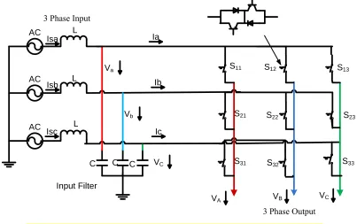
series. Each power switch is bi-directional in nature with anti-parallel connected Insulated Gate Bi-polar Transistors (IGBTs) and diodes. The input is similar to a phase to three-phase Matrix Converter having LC filters.
AC
AC
AC Isb
VA VB VC
Va
Vb
VC
Ia
Ib
Ic
Input Filter Isa
Isc
S11 S12 S13
S21 S22 S23 S
2k
S1k
S31 S32 S33 S3k
Input
K phase Output
Vk
L
L
L
C C C
Fig. 2.1. Power Circuit topology of Three-phase to k-phase Matrix Converter.
with multi-phase output have quickly gained in importance, with a significant number of papers dealing with the subject as discussed in references [2.46]-[2.54]. This is a consequence of accelerated pace of developments in the multi-phase drive area in general.
The determination of appropriate PWM method for complex Matrix Converter topology, especially for multi-phase output, is a key issue. The restrictions imposed on the PWM strategies are that the input phases must not be short circuited and none of the output phases should be open circuited.
The early modulation method, proposed by Alesina and Venturini as shown in reference [2.34] for three-phase to three-phase Matrix Converter, may still be extended for multi-phase Matrix Converter topology with little modifications, but the output voltage magnitude will once again be limited to 50% of the input voltage magnitude. Thus it is not practical to use this method due to the restricted output voltage magnitude. Space vector PWM approach used for three-phase to three-phase Matrix Converter, offering higher output voltage magnitude as given in reference [2.34], although extendable to multi-phase topology as presented in reference [2.52], is highly complex due to large number of space vectors available. For instance, in a three-phase to five-phase Matrix Converter total number of space vectors generated is 215 = 32768. Nevertheless, due to constraints imposed by the switching actions, only 35 = 243 vectors are useful. Following the analogy with five-phase three-level voltage source inverter, the number of space vectors that can be used to generate sinusoidal output is further limited to 93 as discussed in reference [2.52]. Nevertheless, space vector PWM for real time processing still poses a challenge. The output voltage magnitude with space vector PWM in a three-phase to five-phase Matrix Converter is limited to 78.86% of the input magnitude for linear modulation range. This limit can further be raised by exploiting the over-modulation region. No work has so far been reported on over-modulation of the multi-phase Matrix Converter.
![Fig. 3.5. Double-sided switching pattern in a cycle period Tp [3.7].](https://thumb-us.123doks.com/thumbv2/123dok_us/7935641.1317552/59.612.112.504.71.301/fig-double-sided-switching-pattern-cycle-period-tp.webp)