Electro Magnetic braking System - EMBS
An Improvisation of the Heuristic Anti-Lock Braking System
Naveen. S1 1
Senior Engineer, Sharda Motor Industries Limited – R&D, Chennai, Tamil Nadu-603002, India
Abstract
Development of an existing system demands increase in engineering efficiency with optimization. To entail that, this paper describes the working principle of Electromagnetic Braking System (EMBS) as a supplementary of traditional hydraulic friction brakes. The EMBS system is designed using conventional ABS system with increase in braking response time during all decisive situations, where it replaces the hydraulic pumps with electromagnets.
Dynamic calculations of electromagnetic system assisted with ECU is discussed for different mass loads with respect to the wheel RPM which shows the crucial effect in braking control with effective boost up. The theoretical modelling calculations are shown for better perceptive of the system. Also, this modelling study highlights the thermal stability, easy calibration, weight reduction and cost efficacy of the EMBS.
1. Introduction
Anti-lock Braking System is one among the latest improvements in automobile sector which has increased safety and maneuverability to an all new level. ABS addresses two conditions related to brake application; wheel lock-up and vehicle directional control. Brake application is actually a frictional force acting to reduce speed of the vehicle and it is the traction between the tire and road that actually stops it. (3). In conventional braking methods where when brake is applied with enough force, the wheels are held stiff, restricting the momentum of the vehicle. This condition causes the vehicle to slide uncontrollably. When the wheels are clogged, control over the steering is lost.
ABS systems provides a high level of safety to drivers by not stopping the tires but just reducing the speed of the vehicle by a continuous brake and un-break condition, acting rapidly so that the drivers can stomp on the brake,
stay on it with constant pressure and also steer in the required direction.
It operates in a way that when brakes are applied, wheels do not get clogged and also permits to maneuver the vehicle in desired direction. This condition when the brakes are applied and in ABS the braking is set to on and off is termed “pumping” and in ABS pumping is done 18 times per second. This condition increases the stopping distance of the vehicle but allows steering in the desired direction, allowing the ability of maneuvering the vehicle even in panic braking conditions. Conditions for activation of ABS, tachometer sensors, pumping frequency and many such important factors are managed by an Electronic Control Unit (ECU).
2. Design of Disk Brake
In a disk brake, two friction pads are pressed axially against a rotating disc to dissipate kinetic energy. The surface area of contact between the wheel disk and the brake pads plays a major role in deciding both;
1.The amount of force acting for bring the required deceleration
2.Uniform distribution of force acting on the disc
When the brake pads are new, the distribution of pressure over the disc-pad interface is uniform, i.e.
p=constant
If F is the frictional or axial force applied then,
P=F/A, where A is the area of the brake pad. Friction torque is given by the equation;
Tbraking =
Here, µ is the coefficient of kinetic friction and r is the radial distance of an infinitesimal element of pad. After some time the pad gradually depletes away due to mechanical wear. ([2])The wear becomes uniform after sufficiently long time when,
pr = constant = c
F=
The braking torque is,
Tb = µ
3.
Material Properties
The most important member in a braking system is the frictional material. A good frictional material is to possess the following properties;
High and reproducible coefficient of friction
Imperviousness to environmental conditions
Ability to withstand high temperature(thermal stability)
High wear resistance
Flexible and conformability to any surface
4.
The Framework
The assembly of the EMBS has the following child parts, integrated to bring the reactions of a normal disk/drum brake but using electro magnets. The challenge here is to design a circuit that shall understand the braking situation and react to the conditions. The functioning shall be explained in the later stages of the paper;
1.Electro Magnets-The brake shoes.
2.Brake disks- A material that has negligent opacity for magnetic field.
3.ECU- Electronic Control Unit which serves as the heart of the system.
There is a requirement for a lot of sensors to read and send feedbacks to assist the braking conditions.
Sensor 1: Speed sensor to read the acceleration speed of the wheel and send feedbacks continuously to the ECU. Sensor 2: Pressure sensor is to measure the pressure applied by the driver on the brake pedal and send feedbacks to the ECU.
Sensor 3: Measures the total weight of the vehicle at any point of time and sends the value to ECU.
Figure 1. Frame work of the EMBS system
5.
Functioning
5.1. The Power train
The train of functioning for the braking system is between the pressure applied on the brake pedal and the force acting on the brake shoes to provide the required frictional force between the brake shoes to reduce the momentum of the vehicle.
5.2. ECU (Electronic Control Unit)
ECU serves as the heart of the system. The electro-magnets are placed on the brake shoes and are activated by the ECU which supplies electric signals to them. Alternating positive and negative pulse is fed to one electro magnet and the other is fed with a direct pulse. This creates a situation wherein, when the pulse in the two electro magnets is opposite, they are attracted and braking is actuated. When the pulses in them are alike, they repel and now the tires are free to rotate. This EMBS shall perform at pumping rates (18 pumps per second).
5.3. Feedback Assistance;
A pressure sensor is mounted to read the pressure applied on the brake pedal by the driver and sends feedbacks to the ECU which shall send a calculated force to the brake pads depending on the signals received.
A speed sensor is mounted which served to continuously send feedbacks of the acceleration at that point of time to the ECU.
The working of the EMBS is tailored and the mechanism is fed to the ECU which controls the functioning based on the feedbacks received.
This will ensure that every conditions of braking are taken into account to make the EMBS react alike the normal brakes.
6.
Conditions
1. Panic conditions when the pressure applied on the brakes are higher.
2. Normal condition when the driver wants to slowly stop the vehicle
Depending upon the feedbacks received from both the sensors, the ECU decides the amount of attraction force that has to be produced between the electromagnets (brake shoes) and also does the math for the distance and time to stop the vehicle. To make this possible, the ECU should be able to sense and calculate the required force needed at every point of time when the brakes are activated.
The ECU is designed based on Newton’s Laws of Motion. There are two basic rules on which the system functions which are stated below;
A linearly ascending relation between the pressures applied to the brake pedal and the attraction force that has to be produced - direct proportionality between the two variables.
Figure 2. Pressure Vs Force
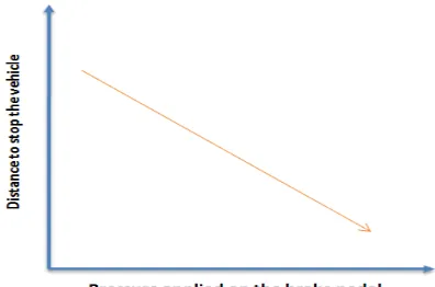
1.A linearly descending relation between the pressures applied to brake pedal and distance to stop. An in-direct proportionality between the two variables.
Figure 3. Pressure Vs Distance to stop
5.4. Condition 1
When the vehicle is moving at a speed greater than 30 km/h and the pressure sensor detects panic conditions.
Figure 4. Panic condition @ speed > 30km/h
Here ECU sends pulses based on Newton’s third equation of motion,
v2 = u2 + 2as ... 1
The retardation value can be obtained from the above equation. This retardation is then used to calculate the time required for stoppage, using the below formula.
S = ut + ½ at2 … 2
Now, we can calculate the force that is required to impart the required retardation to the moving body having a mass of ‘m’ kg approximately.
F = ma …3
Now the force generated from ECU will be given a leverage of 3 times the force required to stop the vehicle and hence the generated value is higher considering the panic condition. This will ensure that the distance to stop is drastically reduced and also the maneuverability of the vehicle is still possible.
5.5. Condition 2
Figure 5. Normal condition @ speed >30km/h
Here, as per the feedbacks from the 3 sensors, the ECU does the math and sends the required force of attraction for the vehicle to reduce momentum. In this scenario there is no leverage since the pressure sensor reads a normal braking condition.
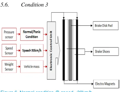
5.6. Condition 3
Figure 6. Normal condition @ speed <30km/h
When the vehicle is moving at a speed less than 30 km/h, there is no need for the pumping mechanism of EMBS and hence normal braking is employed.
The signals to the electromagnets are constantly opposite and the attraction force required is calculated depending on the total mass of the vehicle and sent from ECU which will help to decelerate and halt the vehicle.
Figure 7. Framework of EMBS with speed sensor
7.
Concept Drawings
The concept drawings shall give a pictorial explanation of the working mechanism of EMBS.
After the brake is applied in any condition above 30 km/h, the ECU sends direct negative polarity signal to one electromagnet and the electromagnet is supplied with signals which varies between negative and positive polarities at least for every 1/18th of a second(0.055 s).
Figure 8. Electromagnets with +ve and –ve polarity deceleration
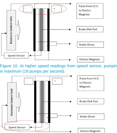
Figure 10. At higher speed readings from speed sensor, pumping is maximum (18 pumps per second).
Figure 11. At lower speed readings from speed sensor, pumping is minimum to halt vehicle
Considering any situation of malfunctioning of the EMBS, it can be effectively active always on the maneuvering wheel and the rear can be conventional system. This shall avoid discrepancies during any kind of system failure.
8.
Conclusion
The ideology to replace the hydraulic system of an ABS with electro magnets has many merits in addition to the effectiveness and the advanced safety features.
1. Reduced packaging constraints.
2. Increased range of application since very low manufacturing cost.
3. Less complicating design.
4. Achieve high level of effectiveness.
5. Can be active always as ECU alters the pumping speed in concurrence to the speed of the vehicle read by the speed sensors.
6. Packaging is easy and compact
7. Suits any vehicle with commonised ECU, only the electromagnets needs to be designed to requirements
8. Cost effective and can be implemented in both two wheelers and four wheelers
References
The heading of the References section must not be numbered. All reference items must be in 8 pt font. Please use Regular and Italic styles to distinguish different fields as shown in the References section. Number the reference items consecutively in square brackets.
1. Patent publication number: US5746294 A;
Publication Type: Grant; ApplciAiton Number: US 08/856, 685; Publicaiton Date: 5 May 1998; Inventor: Jae-Woong Lee, Kia Motors
2. William Gaskey, Sandip Mistry, Duy Nguyen, Jee Yoon; ELET4308/12652, University of Houston College of Technology – Fall 2006, “Electromagnetic Braking System”.
3. Sevvel. P, Nirmal Kannan. V, Mars Mukesh, Magna College of Engineering,” IJIRSET – Innovative Electromagnetic Braking System”.
4. Akshaykumar.S.Puttewar, Nagnath. U. Kakde., Huzaifa.A. Fidvi, Bhushan Nandeshwar, Dr. Babashaheb Ambedkar College of Engineering & Research, Wanadongri, Nagpur, “ Enhancement of Braking System in Automobile using Electromagnets”.
1
Naveen.S, born in Coimbatore District, Tamil Nadu, India, completed his Mechanical Engineering in Amrita University in 2010. He is working as a Senior Engineer in Sharda Motor Industries limited, R&D, Chennai. He is a research and target oriented engineer with skill and global exposure to automobile exhaust product development. He has rich understanding and diversified exposure in the field of product lifecycle management. Having completed his Masters in Automotive Engineering from Staffordshire University, UK (2013), he has strong knowledge in DMAIC methodology to handle projects from concept definition, to manufacturing. He has an eye for intricate details to optimize vehicle emissions, CO2 control and fuel