FOR SYSTEMS WITH STIFFNESS AND DISPLACEMENT
CONSTRAINTS
by
Due Nha Chu
Thesis submitted to Victoria University of Technology
in fulfilment of the requirement for the Degree of
Doctor of Philosophy
DEPARTMENT OF CIVIL AND BUILDING ENGINEERING VICTORIA UNIVERSITY OF TECHNOLOGY
AUSTRALIA
The research work described in this thesis was carried out at the Department of Civil
and Building Engineering, Victoria University of Technology, Melbourne, Austialia,
under the supervision of Dr. Y. M. Xie and Mr. A. Hira. The author would like to
thank both supervisors for their valuable guidance and assistance. The author would
also like to thank Prof G. P. Steven of The University of Sydney for his help and
encouragement.
The author wishes to express his appreciation to:
• The Australian Government, for financial support given in the form of a
scholarship through Australian Agency for Intemational Development (AusAID).
• The Vietnamese Government, especially Ministry of Education and Training for
all its support.
• The Department of Civil and Building Engineering, Victoria University of
Technology, for providing resources and equipment for the research.
• The Intemational Affairs Branch and Postgraduate Studies Unit, Victoria
University of Technology, for their assistance.
Finally, the author would like to thank all members of his family, especially his wife
and children, for their encouragement and support throughout the course of the
studies. Appreciation is also devoted to his friends and colleagues for their helps and
This is to certify that except where specific reference to other investigation is made,
the work described in this thesis is the result of the candidate's own investigations.
Candidate Principal supervisor Co-supervisor
This is to certify that neither this thesis, nor any part of it, has been presented or is
being concurrently submitted in candidature for any other degree at any other
university.
Candidate
This thesis presents the development of an evolutionary method for optimization of
stmctures subject to displacement and stiffness constraints. Using an optimality
criteria approach, the study provides a rigorous mathematical basis to the recently
proposed evolutionary stmctural optimization (ESO) method. New types of
sensitivity numbers for element removal have been formulated from the optimality
conditions of the general weight minimization problem. The optimal shape and
topology of a stmcture is obtained by repeated finite element analysis and element
removal until the sensitivity numbers become uniform by which the optimality
conditions are satisfied, or no further improvement in the objective can be achieved.
It is shown that the method can be applied to other constraints on generalized
displacements, stiffness, stress and frequency. Investigations on various aspects of the
proposed method have been carried out to show its validity and efficiency for shape
and topology optimization.
Page
Summary iv
List of abbreviations viii
Notations ix
List of figures xiv
List of tables xviii
Chapter 1 Introduction 1
1.1 Introduction 1
1.2 Aims and scope of investigation 2
1.3 Outline of the thesis 4
Chapter 2 Background and literature review 7
2.1 Background 7
2.1.1 Classification of stmctural optimization problems 7
2.1.2 Main approaches to stmctural optimization 12
2.1.2.1 Mathematical programming methods 12
2.1.2.2 Optimality criteria methods 12
2.2 Review on recent developments in stmctural optimization 20
2.2.1 Sizing optimization 20
2.2.2 Shapeandtopology optimization of continuum stmctures 23
2.2.3 Tmss topology optimization 27
2.3 Stateoftheartof evolutionary stmctural optimization (ESO) 30
2.3.1 Original evolutionary procedure for stress optimization 30
2.3.2 Evolutionary procedure for frequency optimization 32
for topology problems - Theoretical basis 39
3.1 Introduction 39
3.2 Problem formulation 40
3.3 Sensitivity analysis 42
3.3.1 Effect of element removal on displacements 42
3.3.2 Sensitivity numbers for element removal 45
3.3.2.1 Single displacement constraint 45
3.3.2.2 Multiple displacement constraints 49
3.3.2.3 Method for determination of the Lagrange multipliers 51
3.3.2.4 Constraint limit scaling versus design variable scaling 54
3.3.2.5 Multiple displacement constraints and multiple load cases 58
3.4 Evolutionary procedure for topology optimization 59
3.5 Generalization to other constraints 66
3.5.1 Generalized displacement constraints 67
3.5.2 Stiffness constraints 69
3.5.3 Stress constraints 71
3.5.4 Frequency constraints 73
3.6 Concluding remarks 74
Chapter 4 Topology optimization of skeletal structures
-Application of the ESO method 75
4.1 Introduction 75
4.2 Singularity of the stiffness matrix and measures for prevention 76
4.3 Computer implementation for topology optimization of skeletal stmctures 80
4.4 Examples oftmss topology optimization 83
4.4.1 Two bar tmss 83
4.4.4 Arch bridge under multiple load cases 102
4.5 Concluding remarks 106
Chapter 5 Topology optimization of continuum structures
-Application of the ESO method 109
5.1 Introduction 109
5.2 Singularity of the stiffiiess matrix and a measure for prevention 110
5.3 Computer implementation for topology and shape optimization of
continuum stmctures 110
5.4 Examples of topology optimization of continuum stmctures 113
5.4.1 Short cantilever 113
5.4.2 The Michell type stmcture 117
5.4.3 The MBB beam 120
5.4.4 Plate in bending 122
5.4.5 Stmcture under multiple displacement constraints 125
5.4.6 Stmcture under multiple load cases 129
5.4.7 Bridge with a moving load 131
5.5 Concluding remarks 136
Chapter 6 Investigation on various aspects of the ESO method
for topology optimization 137
6.1 Intioduction 137
6.2 Aspects of the ESO method in tmss topology optimization 138
6.2.1 Influence of the element removal ratio on optimal topology for tmsses 138
6.2.1.1 Tmss stmcture with a grid of 11 x 25 nodes in a domain
of 2 m X 1 m 141
6.2.2 Influence of the ground stmcture on optimal topology for tmsses 145
6.2.2.1 Influence of the ground stmcture on the solution for a tmss
stmcture in a domain of 1 m x 2.4 m 145
6.2.2.2 Influence of the ground stmcture on the solution for a cantilever
tmss in a domain of 2 m x 1 m 149
6.3 Aspects of the ESO method in topology optimization of continuum stmctures 153
6.3.1 Influence of the element removal ratio on topology solution for
two-dimensional continuum stmctures 154
6.3.1.1 The MBB beam 155
6.3.1.2 Stmcture under multiple displacement constiaints 159
6.3.1.3 Bridge with a moving load 162
6.3.2 Influence of mesh size 165
6.3.3 Influence of element type 170
6.3.4 Problem of checker-board patterns 173
6.4 Concluding remarks 176
Chapter 7 Evolutionary structural optimization method for discrete
sizing problems - Theory and application 180
7.1 Introduction 180
7.2 Minimum weight design subject to displacement constiaints 182
7.2.1 Problem formulation 182
7.2.2 Effect of element sizing on displacements 183
7.2.3 Sensitivity numbers for element reduction 185
7.2.3.1 Single displacement constraint 185
7.3.3.2 Multiple displacement constraints 187
7.2.6 Examples of weight minimization 194
7.2.6.1 Plate in bending 194
7.3.6.2 Plate under multiple displacement constraints 200
7.3.6.3 Plate under torsional loading 206
7.3 Minimum displacement design subject to weight constraint 208
7.3.1 Problem formulation 208
7.3.2 Sensitivity analysis 209
7.3.3 Evolutionary procedure for displacement minimization 213
7.3.4 Computer implementation for displacement minimization 215
7.3.5 Example of minimum displacement design for a plate in bending 216
7.4 Maximum stiffiiess design subject to weight constraint 220
7.4.1 Problem formulation 220
7.4.2 Sensitivity analysis 220
7.4.3 Evolutionary procedure for stiffness maximization 222
7.4.4 Examples of stiffness maximization 223
7.4.4.1 Maximum stiffness design for a cantilever plate 223
7.4.4.2 Maximum stiffness design for a plate under torsional loading 226
7.5 Concluding remarks 228
Chapter 8 Conclusions and recommendations for further investigation 230
8.1 Conclusions 230
8.2 Recommendations for further investigation 232
References 234
ECR Element Changing Ratio
ERR Element Removal Ratio
ESO Evolutionary Stmctural Optimization
ESOTOPO Program for topology optimization for tmss/frame stmctures
ESOSHAPE Program for shape and topology optimization for plate/shell stmctures
ESOSZPLT Program for weight minimization for plate/shell stmctures
ESODOPLT Program for displacement minimization and stiffness maximization for
plate/shell stmctures
ESR Element Shifting Ratio
ER Evolutionary Rate
FE Finite Element
FEA Finite Element Analysis
FEM Finite Element Method
MRR Material Removal Ratio
MSR Material Shifting Ratio
RR Rejection Ratio
RS Removal Stiategy
2D two-dimensional
a design variable scaling parameter
{a/} eigenvector inyth mode
b step control parameter
Cf, Cy element contribution or element strain energy
C, C stmctural response
Cjj ith term of stmctural responses
C*, Cj* limiting values for stmctural responses
Di value relating to rth element
E Young's modulus
Cj, Cjj energy density within ith element
/ objective function
f ith term of the objective function
{E} virtual unit load vector
constraint functions
Ith term of the constraint function
i,j, k indices
kj j'th modal stiffness
[K\ stiffness matrix of a stmcture
[K*] stiffness matiix of a stmcture after removing an element
[K% [K'] element stiffness matrix
/ number of real load cases
L Lagrangian function
L^ dimension along jc axis
Ly dimension along y axis
m number of constiaints or number of virtual imit loads
[M^] element mass matrix
n number of design variables or number of finite elements
p index or step control parameter
P point load
{P}, {P^} real nodal load vectors
q index or step control parameter
Q point load
r step control parameter
R radius
s number of generalised displacement constraints
Sj, Sj/^ element strain energy
S, S^. strain energy
Sj^* limiting value for strain energy
t, tg thicknesses of plate elements
{w}, {M^} displacement vectors
{ul} virtual displacement vectors
{u'}, {«'*} element displacement vectors
{uv} element virtual displacement vectors
Uj constiained displacement
Uj* limiting value for absolute value of constiained displacements
V, element volume
Wj element weight
W stmcture's weight or weight objective function
Wj ith term of the weight objective function
X design variable vector, X={ x j , . . . , x„}
Xi design variables
ttj, a,y, a,y^ element virtual energies (or contributions)
A a , " , Aa,y' change in element virtual energy due t o size reduction
Aa,"*", Aajy"*" change in element virtual energy d u e t o size increase
[AK] change in stiffness matrix
[A^'], [AA?] change in element stiffness matrix
[AK'Y change in element stiffness matrix due to size reduction
[A/C']"'' change in element stiffiiess matrix due to size increase
Akj change in m o d a l stiffiiess
Am, change in modal mass
At change in thickness
{Aw} change in displacement vector
AM change in displacement component
AA., change i n eigenvalue
5 tolerance
p, m a s s density
X, Xj Lagrange multipliers
V Poisson's ratio
^e element v o n Mises stress
" max m a x i m u m v o n M i s e s stress
(p limit scaling parameter
(Py parameter characterising the activeness of a constraint.
Y,, Y,y sensitivity n u m b e r for single constraint
INTRODUCTION
1.1 Introduction
Stmctural optimization aims at finding the shape of a stmcture which will carry a
given set of loads and has minimum weight or minimum manufacturing cost while
satisfying constraints on various stmctural factors including stresses, displacements,
natural frequencies and buckling loads.
Initially, the development of stmctural optimization was mainly based on analytical
methods using variation calculus. Analytical methods give basic understanding of
stmctural optimization, however they are not capable of dealing with practical
problems. Only simple stmctures subjected to simple loading and boundary
conditions can be solved by analytical methods.
More recently, stmctural optimization using numerical methods was developed based
on the finite element method (FEM). With the introduction of high speed computers
the finite element method offers a very powerful tool m solving various complex
stmctural problems. A large number of finite element packages have been developed
and used in design. Using the finite element method, two main approaches to
stmctural optimization, mathematical programming and optimality criteria methods,
have been developed and have become important tools in solving practical stmctural
carry out the design sensitivity analysis, where the derivatives of the objective and
constraint functions with respect to all design variables are calculated. For large-scale
problems, the time required for the sensitivity analysis may sometimes become
prohibitive.
Due to the mathematical complexity, the application of stmctural optimization has
gained less popularity compared with the finite element method itself The
development of commercial software for practical structural optimization has been
held back by the lack of a really robust and efficient optimization method suitable for
solving general engineering design problems.
The research described in this thesis is to explore an effective stmctural optimization
method for systems with stiffness and displacement constraints. It is based on the
simple concept that by systematically removing or reducing unwanted material, the
residual shape of a stmcture evolves towards an optimum. The results of a finite
element analysis are used to identify the best location for material removal/reduction.
In doing so, shape and topology optimization can be achieved very easily by repeating
the process of analysis and material removal. Initial investigations have shown that
the proposed technique can be applied to a wide range of engineering problems.
1.2 Aims and scope of investigation
The aim of the study is to develop a generalised method, based on using the finite
element method and the concept of material removal, for optimization of stmctures
subject to displacement and stiffiiess constraints. Shape, topology and sizing
optimization problems will be considered. Computer programs are developed and
The study focuses on the following points:
1. To develop an efficient scheme to evaluate the effect of removing or sizing finite
elements on a specified displacement or the stiffness of a stmcture under a given
set of loads. This is referred to as sensitivity analysis.
2. To develop a stmctural optimization procedure based on the idea of systematically
removing or sizing elements to obtain an optimal design of the stmcture while
keeping specified displacements or the stiffness within the given limits, i.e.
satisfying displacement or stiffness constraints.
3. To develop computer programs for calculating the effect of removing or sizing
elements on specified displacements or stiffness and link these programs to a
finite element analysis package, to carry out the stmctural optimization process
automatically, so that it can be used as a design tool for stmctural design.
4. To investigate various aspects of the proposed method to prove the validity and
efficiency.
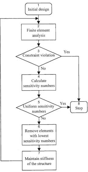
The initial design domain represented by a finite element model is chosen so that it is
big enough to cover the total allowable space. The finite element analysis will reveal
that not all material is effectively utilised. Using a selected rejection criterion, the
ineffective material will be eliminated resulting in a more efficient stmcture.
Generally the optimum stmctiire cannot be achieved in one step. The optimization
process has to be evolutionary, where only a small amount of material is removed at
each iteration. The cycle of analysis and material removal continues until a desired
optimum is reached, for example, when a specified displacement reaches its given
The finite element analysis package STRAND6, developed by G+D Computing Pty.
Ltd. in Australia, is used as the tool for the analysis phase. Computer programs for
the sensitivity analysis and element removal or sizing are developed by the candidate
and linked to the FEM package STRAND6. The same computer programs may be
linked to other commercial finite element codes with few modifications.
Depending on the type of stmctures to be optimised, the type of elements can be
beams, plates or bricks. However, this study concenfrates on two-dimensional
continuum stmctures modelled using plate/shell elements and skeletal stmctures
(tmsses, frames) modelled using beam/bar elements. It is assumed that all materials
behave within the linear elastic range.
1.3 Outline of the thesis
The thesis consists of eight chapters, a list of references and appendices. A literature
review on stmctural optimization, with a particular emphasis on shape and topology
optimization and on a background of the evolutionary stmctural optimization method
is provided in Chapter 2.
Chapter 3 presents the theoretical basis of the evolutionary stmctural optimization
method for shape and topology problems with displacement constraints, which
include the problem formulation, sensitivity analysis and evolutionary optimization
procedures for a single constiaint, multiple constraints and multiple load cases.
Chapter 4 presents the application of the proposed method to tmss topology
optimization. The problem of singularity of the stiffiiess matiix is encountered. A
continuity of the optimization process. A number of examples are provided to show
the effectiveness of the proposed method.
Chapter 5 presents the application of the proposed method to shape and topology
optimization of two-dimensional continuum stmctures. A measure for avoiding
singularity of the stiffness matrix is provided. The evolutionary method is able to
perform shape and topology optimization simultaneously or pure shape optimization.
Examples are provided to show the capability of the proposed method.
Chapter 6 provides a comprehensive study on validity and reliability of the proposed
method for shape and topology problems. Various aspects of the proposed method
including influences of element removal ratio, ground stmcture, mesh size and
element type are discussed. Additional steps for obtaining solutions without
checker-board patterns for two-dimensional continuum stmctures are also suggested.
Chapter 7 presents the evolutionary stmctural optimization method for discrete sizing
problems, which includes problems of minimum weight design of stmctures subject
to displacement constraints and minimization of a specified displacement or stiain
energy of stmctures subject to a constiaint on the weight. For these problems,
suitable types of sensitivity numbers and evolutionary optimization procedures are
formulated. The proposed method is capable of dealing with discrete design variables
directly. Examples of optimum design of plates with discrete variable thicknesses are
provided.
Chapter 8 summarises the findings of this study. Some recommendations for further
A list of references includes only works which are closely related to the study and
directly referred to in the thesis.
BACKGROUND AND LITERATURE REVIEW
2.1 Background
2.1.1 Classification of structural optimization problems
In general, three major criteria need to be satisfied in the design of all stmctures:
strength, rigidity and stability. For a particular type of stmcture one or more of these
requirements govems the design. For example, the strength requirement is the
dominant factor in the design of low-height buildings. However, for high-rise
buildings, the rigidity and stability requirements are more important and are often the
dominant factors in the design. Furthermore, lateral deflections and the peak
acceleration at the top floor of high-rise buildings should be limited to acceptable
levels to satisfy the standpoints of serviceability and comfort (Taranath 1988).
Optimal designs in terms of least weight (cost) while maintaining the sttength,
rigidity, stability and serviceability of stmctures within the required limits, have been
continuously sought.
Stmctural optimization aims to reduce the weight (cost) or improve the behaviour of
the stmcture while satisfying certain requirements. The basic concepts and solution
methods in stmctural optimization can be found in Gallagher and Zienkiewicz (1973),
Morris (1982) and Haftka et al (1990). The type of stioictural optimization problem
In stmctural optimization, the following criteria can be treated either as the objective
or as constraint functions:
(1) weight (volume);
(2) displacement at a given point;
(3) maximum displacement in the stmcture;
(4) stress (several types) at a given point;
(5) maximum stress (several types) in the stmcture;
(6) buckling load factor;
(7) frequencies;
(8) overall stiffiiess.
Different combinations of these entries from the above list lead to different
optimization problems. The most common stmctural optimization problem is usually
stated as
Minimize the weight (volume) of a structure
subject to constraints imposed on some structural responses
(one or more entries from (2)-(8)).
Another kind of stmctural optimization problem is often stated as
Optimize structural response (one of entries (2)-(8))
subject to a weight (volume) constraint.
A mathematical statement for a general optimization problem can be given as
Find the setX, that will
minimize f(X)
subject to gj(X) <0 (f^l,m) (2.1)
where f(X) - objective function;
gj(X) - constraint functions;
X= {xj, ..., x„} - design variables;
x^ andx^ - lower and upper limits for x,.
The constraints may be given in the form of equality or inequality conditions. The
additional constraints imposed on the design variables are called side constraints.
There are also equality constraints in the form of equilibrium and compatibility
conditions which are usually satisfied as a sub-problem via fmite element analysis
and, therefore, are often not included in the general statement of optimization
problems.
The objective and constraint functions can be either linear or non-linear fimctions of
design variables. When all the objective and constraint functions are linear functions,
the problem is a linear optimization problem. When at least one of them is a
non-linear function of design variables the problem becomes a non-non-linear optimization
problem. Most stmctural optimization problems are highly non-linear where the
objective and/or constraint functions are implicit fimctions of design variables. When
the objective and constraint fimctions are expressed as a sum of functions, and each is
a function of only one design variable, i.e.
f(X) = tf(x,) (2.2)
;=1gj(X) = tgy(x,) (2.3)
/•=i
they are separable functions and the problem is referred to as a separable optimization
problem. Separability is an important feature in derivation of the optimality criteria
When all design variables are continuous, i.e. they can have any value between the
given lower and upper limits, the problem is called as a continuous variable problem.
In many cases, where one or more design variables can have only a certain value from
a set of discrete values, the problem is referred to as a discrete variable problem.
Design variables can be any quantity relating to description of the geometry of
stmcture (nodal coordinates), member sectional dimensions, member
cross-sectional properties, member material properties and topology (the pattem of
connection to nodes by members or member cormectivities), which are required to be
determined in the solution process. Each type of design variables requires different
mathematical approach. Depending on the nature of the design variables, stmctural
optimization problems are commonly classified in three types: sizing optimization,
shape optimization and topology optimization problems.
Sizing optimization problems: In sizing optimization problems the geometry (nodal
coordinates) and topology (member cormectivities) of stmctures are fixed. Sizing
design variables may include bar cross-sectional areas, beam element cross-sectional
dimensions, cross-sectional properties (cross-sectional area, moments of inertia) and
plate/shell element thicknesses. They may also include the material properties such as
Young's modulus, Poisson's ratio as in optimization of composite stmctures.
Shape optimization problems: In contrast to sizing problems, the shape of stmctures
is to be determined in shape optimization problems. The exterior and interior
boundary shapes of the stmctures are changed. In such a shape optimization process,
no new holes (cavities) can be created, i.e. topology of the stmcture remains the same.
Design variables in shape optimization problems can be nodal coordinates relating to
Often the term shape optimization is used in a narrow sense referring only to the
optimal design of the shape of the boundary of two- and three-dimensional stmctural
components. In the broad sense, shape optimization can be any problem where it is
needed to change the position of nodes of the finite-element model. In this sense it
also includes geometry (or configuration) optimization of skeletal structures (frames
and tmsses) where joint locations are design variables. In more general case, besides
nodal coordinates, member cross-sectional dimensions (sizing variables) are also
included into design variables.
The above definition for shape optimization is related to more traditional methods
where shape optimization is achieved by changing nodal coordinates. Other methods
using the ground stmcture approach can also perform shape optimization by removing
elements only from the existing boundaries. Although nodal coordinates have never
changed in these methods, a new shape of the stmcture is formed by those extemal
nodes, to which remaining elements are connected.
Topology optimization problems: With reference to the finite element method,
topology optimization is any problem where the pattem of element coimectivity to the
nodes needs to be determined. Topology optimization of continuum stmctures
involves creation of intemal holes. Topology optimization of skeletal stmctures seeks
the number and spatial sequence of elements, joints and supports. During topology
optimization elements can be removed from the stmcture. Topology design variables
are usually the variables which are able to describe the presence or absence of each
element. When the position of nodes are allowed to change, the nodal coordinates are
also design variables. In this case simultaneous shape and topology optimization is
performing. The most general optimization problems can include topology, shape and
2.1.2 Main approaches to structural optimization
The main approaches to stmctural optimization are mathematical programming and
optimality criteria methods. Recent developments of these approaches to stmctural
optimization can be found in Kamat (1993).
2.1.2.1 Mathematical programming methods
Mathematical programming offers a general tool for stmctural optimization. It
includes linear programming, penalty fimction method, feasible direction method,
sequential linear programming and sequential non-linear approximate optimization
(Vanderplaats 1993). These methods require calculation of derivatives of objective
and constraint functions with respect to all design variables, which is referred to as
sensitivity analysis (Arora and Haug 1979; Adelman and Haftka 1986). Often,
repeated finite element analyses are performed to carry out the sensitivity analysis,
which is very costly for large problems. The computational time for sensitivity
analysis sometimes becomes prohibitive. Many approximation methods and
techniques have been developed and employed, to improve the efficiency of the
sensitivity analysis and optimization algorithms (Vanderplaats et al. 1991).
2.1.2.2 Optimality criteria methods
Fully stressed design: Fully stressed design is the earliest intuitive optimality criteria
approach for strength optimization of stmctural systems. In the simplest procedure,
the design variables, for example member cross-sectional areas, are scaled by the ratio
of the element stiess to the allowable stiess using the formula
A , — A , ^'- I (2.4)
where a, is the stress of the ith element and cr" is the allowable stiess. The ratio o/a^
is called the stress ratio. An iterative process of analysis and design ratiorung can
result in a stmcture where all members, except those which are at the minimum
gauges, are fully stressed, i.e. their sfresses are at allowable level.
Fully stressed design procedures are very attractive and efficient in the sense that the
iterative process usually converges in few iterations. The shortcomings of the method
is that it can not necessarily give minimum weight designs due to the fact that no
objective is involved. It has been pointed out later that the fully stressed design
method can give minimum weight designs only for statically determinate stmctures
under a single loading condition with equal allowable stresses on tension and
compression. However, because of its effectiveness, this method is still used to get a
starting point for more rigorous optimization procedures (Gallagher and Zienkiewicz
1973; Morris 1982).
Optimality criteria methods: Rigorous optimality criteria methods try to satisfy the
Kuhn-Tucker necessary conditions for optima. A common criterion is that the stiain
energy density in each member of the stmcture should be uniform. A recursive
formula is derived which leads to the desired solution using iterative process. Is was
pointed out by Fleury (1979, 1980) that mathematical programmmg and optimality
criteria methods have a common basis in the duality of the original problem
statement. Optimality criteria is valid for a mathematically separable problem. The
optimality criteria approach is shown to be quite effective as a design tool. Its
principal attiactiveness is that the method can be easily programmed for the computer,
is relatively independent of problem size, and usually provides a near optimum design
with relatively smaller number of detailed stiiictural analyses compared with
The common approach to optimality criteria methods is the Lagrange multiplier
method. The separability of the objective and constraint fimctions with respect to the
design variables, i.e. equations (2.2) and (2.3) are satisfied, is the most important
condition for derivation of optimality criteria (Berke and Khot 1988). Following the
standard procedure, the constrained optimization problem (2.1) is replaced by the
unconstiained problem of minimizing the so-called Lagrangian which is formed as a
combination of the initial objective and constraint functions. For the ease of reference
and simplicity in discussion, the optimality criteria method is summarised below. The
summary is mainly based on the work by Berke and Khot (1988). The result can also
be found elsewhere in the works by Venkayya et al. (1973) and Venkayya (1993), and
in the books by Morris (1982) and Haftka et al (1990).
The separability of the problem of weight minimization subject to a displacement
constraint can be easily pointed out, if there is only one design variable for each
element, i.e. n (the number of design variables) is also the number of elements. The
separability condition (2.2) is satisfied for the weight objective
W(X) = tw,(x^) (2.5)
/=i
where Wj(Xj) is the weight of the ith element. The separability condition (2.3) is also
satisfied for a displacement constraint. By using the virtual unit load method the
specified constrained displacement, denoted by C, can be expressed as the sum of
element virtual strain energies
C(X)^tq(x,) (2.6)
/=i
where C,(x,) is the virtual strain energy of the rth element. It is assumed that the term
Cj is an explicitly function of only x,. This is justified in statically determinate
functions of all the design variables representing members cross section properties.
The constraint in the problem statement (2.1) will have the form
g ( Z ) = C ( X ) - C * = Z C , ( x , ) - C * < 0 (2.7)
where C* is the given limit for the specified displacement C.
The Lagrangian for the problem of weight minimization subject to a single consfraint
is defined as
L(X,X) = W(X) + Xg(X) = tWj(Xj) + X(tCj(Xj)-C*) (2.8) /=! (=1
where A. is a Lagrange multiplier. The necessary Kuhn-Tucker condition for optima
of the problem is obtained by differentiating the Lagrangian with respect to the design
variables. This gives
dL(X,X) dW(X) dC(X) dW,(x,) dC,(Xj)
— ^ — + X - - — = — - — + x ^ — = 0 (/ = ! , « ) (^-y;
aXj oXj oXj dXj dXj
where separability is utilized. Further derivation of the optimality criteria needs
explicit forms of ^,(x,) and C,(x,) in term of the design variable x^. Berke and Khot
(1988) proposed the following expressions
«^.(x,) = w,x, (i = l,n) (2.10)
Q(x,) = ^ (i = l,n) (2.11)
where w,- is the specific weight. Further specialization, for example, for tmss and
displacement constiaints results in w^ ^ p, /^ and c, = r,T,/, /£„ where p, is the bar
due to the actual load and T^ is the bar virtual force due to the virtual unit load
applied to the location of and in the direction of the constrained displacement.
The optimality condition (2.9) now becomes
Wi-x\ = Q (i = l,n) (2.12)
I
or
Dj=X-^ = X^=l (i^l,n) (2.13)
W;Xf W. II I
or
c,. C,. C,. e,. 1
= — = constant (i = I, n) (2.14)
where
^ixf W. p.v,. p,. X
e, = ^ (i = l,n) (2.15) V.
is the element virtual strain energy density, v^ is the element volume and p, is the
element mass density.
Equation (2.14) states an optimality criterion that at the optimum the ratio of the
element virtual stiain energy density and mass density is equal for all elements. In the
case where all elements are made from the same material, p, is the same for all
elements, the optimality criterion is that the virtual energy density is uniform for all
elements (Venkayya et al 1973).
There are three essential recurrence formulas that are possible to obtain from equation
(2.13). By multiplying equation (2.13) by (x,)'' and taking ^ h root on both sides, the
exponential recurrence formula is obtained in the form as
The linearized form for formula (2.16) is as
^ r = K ( i + i ( A - i ) ) r ' ^ (/ = i, n) (2.17)
If the above steps are performed using reciprocal variables and then reconverting to
the original variables, the linearized reciprocal form is obtained as
.y-new ^i (l-^(Dj-l))\
old
(i = l,n) (2.18)
The parameter q is called a step size parameter. The Lagrange multiplier is
determined from the condition that the constraint is active. In the case of a single
constraint, this condition can be easily satisfied by scaling all design variables without
the necessity of determination of the Lagrange multiplier. It should be pointed out
that in statically determinate stmctures, the term c^ in (2.12) is constant. Formula
(2.12) can be solved for x, and gives the correct optimum value to x, in a single
sizing step.
In problems with multiple constraints, the constrained displacements are expressed as
Cy(^) = i c ^ ( x , ) (j = l,m) (2.19) /=i
where C,y(x;) is the virtual strain energy of the rth element with respect to the yth
constiained displacement and m is the number of constraints. The constraints will
have the form
gj (X) = CJ (X)-C;=t Cy (X,) - C; < O (j = l,m) (2.20)
i=l
where C,* is the given limit for theyth constraint. The Lagrangian will have the form
m n
L(X,X) = i:w.(Xj)+ZXj(I.Cy(Xj)-C;) (2.21)
(=1 j=\ i=l
where A,y (j = I, m) are m Lagrange multipliers. The necessary Kuhn-Tucker
conditions are
dL dWAXj) ^ dCy(Xi)
f^ = -ir-^+I.Xj^-^ = 0 (i = l,n) (2.22)
o x , dXj j=i ^ dXj
The explicit forms of Wj(x^ is the same as in (2.9). Similar explicit forms for C,y(x,)
are given as
^(z-Cy (x,.) = — (i = l, n; j = I, m) (2.23)
X
For a bar member Cy = TyT^ l/Ej where Ty^ is the bar virtual force due to the virtual
unit load applied to the location of and in the direction of the yth constrained
displacement.
The optimality condition (2.22) now becomes
">
C-w , - Z ? L , . - ^ = 0 (i = l,n) (2.24)
or
m Q '" C
D, = YXj-^=YXj-^ = l (i = l,n) (2.25) y=l J WjXf j=i J Wj
or
D, = Z 1 . ^ = 1 (1 = 1, n) (2.26)
7=1 P/
where
C
ey=-^ (/ = 1, « ; ; = !, m) (2-27) V,.
is the element virtual stiain energy density corresponding to the yth constrained
The equation (2.26) expresses the optimal criterion for multiple constraints that at the
optimum the weighted sum of ratios of element virtual strain energy density and mass
density is equal to unity for all elements, where the weighting parameters are the
Lagrange multipliers (Venkayya et al. 1973)
The evaluation of the Lagrange multipliers Xj is important for multiple constraints.
They are determined from conditions that constraints are active. Assuming all
constraints in (2.19) are equality constraints, we have
C =C (j = 1, m) (2.28)
By multiplying by (X,,)'' and taking bth root on both sides of (2.28), the exponential
recurrence formulae for the Lagrange multipliers are obtained in the form as
ynew J
-\old
(j = 1, m) (2.29)
The Lagrange multipliers can also be determined by linear equations which are
obtained by combining the optimality criterion (2.25) and the active constiaint
equations (2.28), where C, is determined by (2.18). The linear equations have the
form
Z J A ^ 2-i
n C.C., »
c*
(j = 1, rn) (2.30)p=\ Aj=iW;X,.y
The incremental procedure based on (2.30) to update Xj is given as follows
p=\
f C.C, I
Ih I ^ = (1 +
P)Cj -pC;
(j=
1, m) (2.31)VJ=I W , . X - J
The formulae (2.29), (2.30) and (2.31) are valid under tiie assumption that constramts
are active. There is a need of a mechanism for keeping constraints active. This can be
easily done by scaling design variables. Thus scaling design variables should precede
the evaluation of the Lagrange multipliers.
The recurrence formulae to update design variables in the case of multiple constraints
have the same forms as in equations (2.16), (2.17) and (2.18), where Z), is given in
equation (2.26).
2.2 Review on recent developments in structural optimization
2.2.1 Sizing optimization
Both mathematical programming and optimality criteria methods were initially
developed for sizing optimization problems where design variables are continuous. A
review of basic developments of these methods has been presented by Vanderplaats
(1981). It is seen that substantial efforts have been devoted to the associated
mathematical and computational backgrounds to improve the accuracy of analysis,
especially the accuracy of sensitivity analysis, to facilitate higher convergence rates
and to ensure the reliability and efficiency of solution algorithms. In this direction,
various approximation concepts and methods have been proposed. A good review on
approximation concepts for stmctural synthesis has been given by Vanderplaats et al
(1991). It is pointed out that constraint deletion, by which only critical or near-critical
constiaints remain under consideration in each step, can help to reduce the
computation time significantly. The use of intermediate variables and responses, for
example reciprocals of cross-sectional properties and member forces, can change
linear dependence. Therefore a linear approximation can be of a higher quality, which
increases the accuracy of sensitivity analysis. The approximate problem is then
formulated and solved without the necessity of full finite element analysis. The result
of the approximate problem is used to update the design and the next design step
commences. Using approximation concepts will reduce the number of costly full
finite element analyses. The current status of this trend in stmctural optimization can
also be found in Kamat (1993). All these attempts aim to apply the optimization
methods to large scale and more complex stmctures.
In many practical applications, the design variables must be selected from a list of
discrete values. For example, stmctural members may have to be selected from
standard sections or thicknesses commercially available from manufacturers. Relating
to practical applications, more attention has been given to dealing with discrete sizing
variables optimization. Huang and Arora (1995) gave an overview of methods for
.solving such problems. It is pointed out that the solution of the mixed
(discrete-continuous) variable optimization problems usually requires considerably more
computation effort compared to the continuous variable optimization problems. Often
the problem is solved for continuous optimal solution by using tiaditional
optimization techniques, such as mathematical programming or optimality criteria
methods, assuming all designs variables be continuous. Then, one of the methods,
such as rounding-off, branch and bound methods, simulated annealing, genetic
algorithm, Lagrangian relaxation methods, is used to get the discrete solution (Huang
and Arora 1995; Ringerts 1988; Sandgren 1990; Schmit and Fleury 1980). The
values given for each discrete design variable are usually required to be close to each
other for validity of converting a continuous optimal solution to a discrete one
Olsen and Vanderplaats (1989) presented a sequential linear discrete programming
method for nonlinear optimization with discrete design variable. The continuous
optimum solution is rounded in a direction away from constiaint violation to get a
starting point for discrete optimization. The approximation techniques are used to
create sub-problems suitable for linear mixed-integer programming method. The use
of a truncated set of discrete possibilities reduces the size of the approximate problem
and hence improves the efficiency. Each discrete design variable is allowed three
possibilities: its present value, the adjacent higher value, and the adjacent lower value.
Examples show that the method gives results with lower weights compared with the
continuous solution and pointed out the potential non-unique solution to a discrete
problem.
The rounding up method is the simplest way to get a discrete solution from the
continuous one. This may result in a large disturbance from the continuous variable
solution. It is recognised that while many design variables are assigned the closest
higher discrete values, it is possible to reduce some of them to the closest lower
discrete values to obtain a feasible design close to the continuous variable solution.
Chan (1994) proposed a pseudo-discrete section selection technique to achieve a
smooth progressive transition from the continuous variable design to the optimum
final design using discrete standard steel sections (see also Chan et al 1994). Once
the continuous variable solution is obtained, the strategy starts selecting sections for
member or group of members involving the least change in material weight. These
members then are treated as inactive by being fixed at the assigned discrete sections.
Other active members may possibly reduce in size by re-evaluating the Lagrange
multipliers and reusing the recursive relation. This section selection process is
2.2.2 Shape and topology optimization of continuum structures
In comparison to sizing optimization, shape optimization is more complex because the
shapes are continuously changing in the design process. The first serious problem
associated with boimdary shape optimization of two- or three-dimensional bodies is
mesh deformation. As the shape of the stmcture changes, the finite element mesh
needs to be updated to maintain an adequate element geometry. Highly deformed
finite elements due to change of boundary will result in loss of accuracy in
calculations of sensitivity derivatives. This problem is addressed by manually
remeshing during the optimization process or by employing sophisticated automatic
mesh generators. Another problem is that of existence or creation of intemal
boundaries or holes. In many problems the optimal design will have intemal cavities.
It is impossible to produce these cavities with a standard optimization approach
without prior knowledge of their existence. One approach to deal with this problem is
to assume that the material is not homogeneous, but instead has an microstmcture
with microcavities in the material (Haftka and Grandhi 1986; Haftka et al 1990, p.
197).
Ding (1986) gave a review on numerical and analytical methods for shape
optimization of stmctures. Several steps in the shape optimization process, such as
model description, selection of the objective function and shape variables,
representation of boundary shape, finite element mesh generation and refinement,
sensitivity analysis and solution methods, are reviewed in detail. Examples of shape
optimization of two- or tiiree-dimensional stmctures are given to show the state of the
art in the mid 80's in shape optimization. Ding (1986) pointed out that careful
consideration has to be given in order to describe the changing shape, to maintain an
impose proper constraints and to utilise existing optimization methods to solve the
shape optimization problems.
Homogenization method
An important recent advance in the shape optimization is the homogenization method
proposed by Bendsee and Kikuchi (1988). In this method a stmcture was represented
by a model of finite elements with microvoids (a micro rectangular hole is included in
each element). By changing the sizes of the rectangular hole the element can become
a complete void or solid, as well as generalized porous medium. The orientation of
such holes is also important. Thus, the sizes and the orientation of the microscale
rectangular holes are the design variables which characterize the porosity of the
porous medium. The objective is to minimize the mean compliance of the stmcture
subject to equilibrium equations and a volume constraint. An optimality criteria
method is used which gives the optimal porosity of such a porous medium. Many
interesting results of the homogenization method can be found in Bends0e and
Kikuchi (1988, 1993), Bends0e (1988, 1989), Suzuki and Kikuchi (1991), Diaz and
Bends0e(1992).
Tenek and Hagiwara (1994) presented a study on optimization of rectangular plate
and shallow shell using the homogenization method. The objective was to minimise
the strain energy function under a volume constiaint. An optimum distribution of
thickness or microstmctural density is sought under the hypothesis that the design
variables can only be assigned their extreme allowable bounds, or values very near
them, so that the material can be removed from low density areas, thus an optimum
topology can be determined. The finite element method was used to obtain the
stmctural response and the feasible direction method was used for the optimization
Another microstmcture-based design domain method, similar to homogenization
method, has been proposed by Gea (1996). New microstmctures in the form of
spherical inclusions are introduced in fmite elements. A closed form of the problem is
achieved which allows the use of linear programming algorithms for optunization
process. The method significantly reduces the number of design variables per element
and can give similar results to that obtained by the homogenization method.
Density function approach
A method proposed by Yang and Chuang (1994) based on an empirical relationship
between the density and the Young's modulus and linear programming techniques,
gave a similar result to that obtained by the homogenization method. The drawback
of the method is in the intuitive relationship between the density and the Young's
modulus.
Changing element connectivity
One possibility to overcome difficulties of changing shape description, remeshing and
creation of cavities is to rely on the entire finite element mesh chosen for the initial
design domain. The shape of the stmcture will be obtained by removing unnecessary
elements from the mesh (e.g. by changing the element connectivities). The key point
in this method is to work out an effective measure to evaluate the importance of each
element to the whole stmcture and an appropriate criterion for element removal. The
idea of element removal has been tried by other researchers such as Maier (1973),
Rodriguez-Velazquez and Seireg (1985), but such studies have not resulted in a
generalized method. A systematic investigation is under way at Victoria University of
Technology and The University of Sydney on the full potential of such a simple but
Atrek (1989) reported an optimization program called SHAPE for shape optimization
of continuum stmctures. The stmcture is represented by a finite element model and
the optimal shape of the stmcture is obtained by removing elements. The program
can optimize the shapes of solid, shell, or plane-stress systems for multiple load cases,
with multiple constraints related to stresses, displacement, and stiffness. Material
may be removed from inside the domain as well as from the boundaries. A linear
maximization sub-problem for Lagrange multipliers has to be solved in order to
identify the optimum locations for element removal.
Evolutionary structural optimization
Recently, a simple approach for shape and layout optimization, called evolutionary
structural optimization (ESO), has been proposed by Xie and Steven (1993). With
this procedure, stmctural shape and layout optimization can be easily achieved using
standard finite element analysis codes. The original idea of evolutionary stmctural
optimization involves obtaining an optimal shape of a stmcture by systematically
removing lowly stressed elements from the stmcture (Xie and Steven, 1993, 1994a).
This method has been extended for frequency optimization problems (Xie and Steven,
1994b, 1996), for which by removing appropriate elements from the stmcture, the
frequency of the resulting stmcture will be changed in a desired direction. A wide
range of examples has been presented by Xie and Steven (1993, 1994a, 1994b, 1996)
to demonstrate the capacities of such an evolutionary procedure for solving stmctural
shape and layout optimization of continuum stmctures.
A recent application of the proposed ESO method is shape optimization of metallic
insert in composite bolted joints (Rispler and Steven 1995). The optimal shape for the
metallic insert is obtained by gradually changing material of highly stressed elements
the high stress concentration and increases the bearing strength of pin loaded and
bolted joints.
2.2.3 Truss topology optimization
In tmss topology optimization problem, one seeks the optimal pattem of connection of
members or the number and spatial sequence of elements, joints, and supports.
Compared with the sizing problem, the topology optimization is much more complex
due to the changes in both the fmite element model and the set of design variables.
Despite the significant difficulties involved in the solution process, it is recognised
that substantial savings can be achieved in topology optimization compared with
sizing optimization (Kirsch 1989, Topping 1993).
Due to the difficulties involved in the topology optimization, various simplifications
and approximations are often used. A common approach to the topology optimization
oftmss stmctures is based on an initial ground structure or structural universe, which
contains many members cormecting to the chosen set of joints. Members are being
removed during the solution process. An optimal solution is obtained as a sub-set of
such a ground stmcture. This approach is referred to as the ground structure method.
Dom et al (1964) were the first to use the ground stmcture approach. Both force and
displacement methods in stmctural analysis are employed in tmss topology problems.
By using the force method and ignoring the compatibility conditions, the tmss
topology optimization problem for a minimum weight can be formulated as a linear
programming problem in member areas and forces. The resulting topology may
represent a statically determinate, statically indeterminate or unstable stmcture.
compatibility conditions. Some modification to account for the elastic compatibility
or stability might be required (Kirsch 1989, 1993).
In the displacement formulations of tmss topology problems, non zero lower bounds
on the cross-sectional areas have been imposed to avoid singularity of the stiffiiess
matrix. One way of tackling this problem is to use special methods for compliance
minimization (Bendsee and Kikuchi 1993; Bends0e and Ben-Tal 1993). The problem
is to find the minimum compliance tmss subject to the equilibrium condition and a
given volume of material. In this formulation, the design variables (bar volumes) and
the displacements appear as independent variables. The presence of the displacements
in the problem formulation does not require a positive definition of the stiffiiess
matrix. This allows to set zero to the lower bound on the design variables and
therefore the bars of the ground stmcture can be removed, and the problem statement
covers topology design. The limitation of the compliance formulation is that only a
constraint on the volume of the tmss is considered.
A more general way for avoiding the problem of singularity of the stiffiiess matrix is
to use the simultaneous analysis and design (SAND) approach which treats
displacements as additional design variables and equilibrium conditions as equality
constraints (Haftka 1985). This method does not require inversion or factorisation of
the stiffness matrix so it can be applied to tmss topology optimization where die zero
lower bounds for design variables are allowed (Sankaranarayanan et al. 1993, 1994).
To reduce the computational time, an additional member elimination strategy is
incorporated into SAND. After every five optimization circles, elements with small
cross-sectional areas are eliminated. An element is removed if its cross-sectional area
is less than 1% of the maximum area in tiie cmrent design and if simultaneously the
approach avoids the problem of singularity of the stiffness matrix, it generally
increases the number of design variables substantially.
A simpler method for the design of stmctures with variable topology, based on
theorems of stmctural variations, is proposed by Majid (1974). The method includes
both stress and displacement constraints. The benefit to weight saving due to removal
of every element is assessed. The member, which gives the largest weight saving
without violating constraints, is removed. However, repeated analyses for a pair of
unit loads acting at the ends of each member are required, which increases the
computation time substantially. Thus, the method is limited only to small size
stmctures due to efficiency considerations
Tabatabaei and Marsh (1993) demonstrated the effect of diagonal removal on space
stmctures. Removing appropriate diagonals creates a more uniform distribution of
forces between chords of equal size, and consequently increases the overall load
capacity of the stmcture. Their examples illustrated that more efficient designs can be
obtained by removing select elements from the given stmcture. However, the
proposed procedure is very time-consuming because repeated finite element analysis
is required for identifying the best element to be removed at each step.
It has been pointed out by other researchers that fully stressed design methods can
also be employed to eliminate members from the ground stmcture. By applying the
stiess ratio procedure to a highly connected ground stmcture, many of the members
will reduce to zero. For a stmcture subject to a single loading condition with stress
constiaints for members in tension and compression at the same level, the resulting
stmctural layout will be the same as that obtained by solving the linear programming
It is worth noting that the selection of a solution method for a particular optimal
design problem greatiy depends on the FEA packages and optimization programs
available to the designer. At present, finite element packages are popular and
accessible to all engineers while optimization programs are less popular because of
the mathematical complexity involved in stmctural optimization problems and lack of
general-purpose optimization programs. The evolutionary stmctural optimization
method offers a simple way to solve optimization problems by using standard finite
element packages. This method is still at the early stage in development. The current
status of this simple method is given in the next section.
2.3 State of the art of evolutionary structural optimization
2.3.1 Original evolutionary procedure for stress optimization
In the original procedure of evolutionary stmctural optimization, proposed by Xie and
Steven (1993), the shape and layout of a stmcture is obtained by gradually removing
lowly stressed elements. A design domain is chosen large enough to cover the final
design and is divided into a fine mesh of finite elements. Loads and boundary
conditions are imposed and a stress analysis is carried out by using a standard finite
element code. It is often revealed that some parts of the material are lowly stressed
and they can be removed from the stmcture. The Rejection Criterion (RC) is based on
the von Mises stress in elements. For a stmcture under a single loading condition,
elements, in which the von Mises stiess is less than a Rejection Ratio (RR) times the
maximum von Mises stiess over the stmcture, will be removed from the stmcture. In
other words, elements are removed if the following condition is satisfied
The cycle of finite element analysis and element elimination is repeated for the same
value of RR until a steady state is reached when no more elements are deleted. At this
stage an Evolutionary Rate (ER) is introduced and added to the RR, i.e.
RR,^^ = RRj + ER (i = 0, 1, 2, 3, 4,...) (2.33)
where / refers to iteration number. The iterative process takes place again until a new
steady state is reached. This evolutionary process continues until a desired optimum
is reached, for example, when all stress levels are within 25% of the maximum. The
absolute best value of the final rejection ratio to terminate the iteration process might
not exist, however the evolutionary procedure provides the possibility of knowing
every stage of shape and layout path towards the final design. The final design is the
optimum in the sense that more uniform stress distribution is achieved.
In this method two parameters, the initial rejection ratio RR^ and the evolutionary rate
ER, are introduced. The typical values RR^ = 1 % and ER = 1% are small enough to
give satisfactory results. For some specific problems where stress levels do not vary
much over the whole design domain, an initial Rejection Ratio as high as 10% and an
evolutionary rate as large as 5% have been suggested and used by these authors.
The previously described evolutionary procedure has been extended to optimal design
of stmctures subjected to multiple load cases (Xie and Steven 1994a). After a finite
element analysis, the ratio of the element stress over the maximum stress is checked
for each load case and an element will be eliminated from the stmcture only if the
ratio is less than current RR. for all load cases, i.e.
'-'max
where a / is element von Mises stress and a*^^ is the maximum von Mises stress over
the current design of the stmcture corresponding to l&^ load case and / is number of
load cases. The process of finite element analysis and element elimination is repeated
with the same value of RR^ until a steady state is reached. By then, the current
rejection ratio is increased by the Evolutionary Rate following the formula (2.33).
The optimization process continues until the final value for the Rejection Ratio is
reached. The final design is optimum in the sense that more uiuform stress
distribution results and every element has its own role to play for at least one load
case and possibly for all load cases. Examples provided by Xie and Steven (1994a)
show that the proposed method can reproduce many existing optimal solutions
obtained by other methods.
2.4.2 Evolutionary procedure for frequency optimization
The evolutionary procedure for frequency optimization has been also proposed by Xie
and Steven (1994b, 1996). The distinction of this method from the previously
described one is the achievement in evaluation of the effect of element removal on the
chosen frequency. Having these effects, it is easy to identify the best elements to be
removed in order to shift the specified frequency in a desired direction.
Following Xie and Steven (1994b, 1996), a stmcture is divided into a fine mesh of
finite elements. The dynamic behaviour of the stmcture in the finite element method
is represented by the follovving general eigenvalue problem
([/q-co2[M]){fl^} = 0 (2.35)
where [K] is tiie global stiffness matrix, [M\ is the global mass matrix, coy^ is theyth
notations from those given in the original works are used to keep a consistency in
notations throughout the thesis.
The eigenvalue C0y2 and the eigenvector {aJ} are related to each other by the Rayleigh
quotient
,2 _ _ Z m
®y = — (2.36)
J
where the modal stiffness kj and the modal mass Wy are defined as
kj = {aJ)''{K\{aJ} (2.37)
mi^{aJ)^[M]{aJ} (2.38)
From equation (2.36) we can find the change of the eigenvalue as
Akj kjAmj \
A((Oy)« ^—= — ( A k j - a j A m j ) (2.39) •^ my mj mj •' ^ ^ ^ ^
In order to obtain the value of A(cOy2) from the information of the previous eigenvalue
analysis, we assume that the eigenvector {cf} is approximately the same before and
after the removal of that element. The assumption that the mode shape does not
change significantly during the design cycles has been commonly used in frequency
optimization. With this Eissumption, the changes in the modal stiffiiess and the modal
mass due to removal of the rth element from the stmcture can be approximated as
Akj^{a^^[K']{a'J} (2.40)
Amj^{an^[M']{a'J} (2.41)
in which [K'] and [M] are the stiffiiess and mass matrices of the rth element. The
element eigenvector {a'J} contains the entries of {at} which are related to the removed
Substituting equations (2.40) and (2.41) into (2.39) we have the approximation of the
change of the eigenvalue due to the removal of an element, i.e.
A(rs,j)^~{a'J}\c,j{M'^-{K'}){a'J} (2.42)
J
To decide which elements should be removed from the stmcture so that the
eigenvalue will increase or reduce, we calculate for each element the following
sensitivity number
<;y ^^{a'JV(c,j[M']-[K']){a^ (2.43)
which indicates the change in the eigenvalue aj^ due to the removal of the rth element.
When only one frequency is considered, the modal mass my in formula (2.43) can be
omitted since it is the same for all elements.
It has been pointed out that the values of C^y for all elements are ranging from a
minimum to a maximum. The minimum is negative and the maximum is positive.
Thus, removing the elements with highest (positive) values of C,y will make a
maximum increase in the frequency of the stmcture and removing the elements with
lowest (negative) values of ^,y will make a largest reduction in the frequency. It is also
possible to reduce the stmctural weight while making the least change in the
frequency by removing elements with C,y close to zero.
The optimal stmcture, however, carmot be achieved in one step. The optimization
process has to be evolutionary. Only a small number of elements (i.e. small amount
of material), should be eliminated from the stmcture at each iteration, for example 1%
of elements (e.g. 1% of material). The evolutionary procedure for frequency