c e-ISSN: 2348-6848, p- ISSN: 2348-795X Volume 2, Issue 11, November 2015
International Journal of Research (IJR)
Available at http://internationaljournalofresearch.orgA Nine Level Inverter Fed Induction Motor Drive for
Energy Saving In Variable Torque Load Application
K.J.SANTHOSH KUMAR
M-tech Student Scholar Department of Electrical & Electronics Engineering, VBIT Engineering College,
Ghatkesar(M), R.R. (Dt), Telangana, India
P.VARAPRASAD REDDY
Assistant Professor Department of Electrical & Electronics Engineering, VBIT Engineering College,
Ghatkesar (M), R.R(Dt),Telangana, India
ABSTRACT
The main objective of this paper is simulation of three phases Nine level inverter fed induction motor drive. Various low quality of power a conventional inverter fed induction machine is due to the presence of harmonics and significant level of energy is loss. The proposed Nine level inverter is used to reduce the harmonics. These inverters are used to generate high quality voltage waveforms. The voltage reference can follow accuracy in nine levels and the befit is to generate voltage can be modulated instead of PWM. In this paper the getting active harmonics are eliminating a specific higher order harmonics of the multilevel converters with unequal DC voltages. This process can be done MATLAB/SIMULATION of three phase nine level inverter fed induction motor.
I. INTRODUCTION
An induction motor being rugged, reliable, and relatively inexpensive makes it more preferable in most of the industrial drives. They are mainly used for constant speed applications because of unavailability of the variable-frequency supply voltage. But many applications are in need of variable speed operations. In early times, mechanical gear systems were used to obtain variable speed. Recently, power electronics and control systems have matured to allow these components to be used for motor control in place of mechanical gears. These electronics not only control the motor’s speed, but can improve the motor’s dynamic and steady state characteristics. Adjustable speed ac machine system is equipped with an adjustable frequency drive that is a power electronic device for speed control of an electric machine. It controls the speed of the electric machine by converting the fixed voltage and frequency to adjustable values on the
machine side. High power induction motor drives using classical three phase converters have the disadvantages of poor voltage and current qualities. To improve these values, the switching frequency has to be raised which causes additional switching losses. Another possibility is to put a motor input filter between the converter and motor, which causes additional weight. The diode clamp method can be applied to higher level converters. As the number of level increases, the synthesized output waveform adds more steps, producing a staircase waveform. A zero harmonic distortion of the output wave can be obtained by an infinite number of levels. In this paper, a three-phase diode clamped multilevel inverter fed induction motor is described. The diode clamped inverter provides multiple voltage levels from a five level unidirectional voltage balancing method of diode clamped inverter. The voltage across the switches has only half of the dc bus voltage. These features effectively double the power rating of voltage source inverter for a given semiconductor device. The proposed inverter can reduce the harmonic contents by using multicarrier SPWM technique. It generates motor currents of high quality. Here the speed of an induction motor is precisely controlled by using seven level diode clamped multilevel inverter.
II. RELATED WORK
c e-ISSN: 2348-6848, p- ISSN: 2348-795X Volume 2, Issue 11, November 2015
International Journal of Research (IJR)
Available at http://internationaljournalofresearch.orgFive-level inverter is limited by voltage ratings of switching devices, the problematic series connection of switching devices is required to raise the dc link voltage. By series connection, the maximum allowable switching frequency has to be more lowered, hence the harmonic reduction becomes more difficult. In addition, the five level inverters generate high frequency common-mode voltage within the motor windings which may result in motor and drive application problems. From the aspect of harmonic reduction and high dc-link voltage level, Five-level approach seems to be the most promising alternative. The harmonic contents of a seven-level inverter are less than that of a five level inverter at the same switching frequency and the blocking voltage of the switching device is half of the dc-link voltage.
III. PROPOSED METHOD
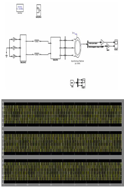
The block schematic of multilevel inverter fed three phase induction motor is show in figure.15. The complete system will consist of two sections; a power circuit and a control circuit. The power section consists of a power rectifier, filter capacitor, and three phase diode clamped multilevel inverter. The motor is connected to the multilevel inverter. An ac input voltage is fed to a three phase diode bridge rectifier, in order to produce dc output voltage across a capacitor filter. A capacitor filter, removes the ripple contents present in the dc output voltage. The pure dc voltage is applied to the three phase multilevel inverter through capacitor filter. The multilevel inverter has 36MOSFET switches that are controlled in order to generate an ac output voltage from the dc input voltage The control circuit of the proposed system consists of three blocks namely microcontroller, opto-coupler and gate driver circuit. The microcontroller is used for generating gating signals required to drive the power MOSFET switches present in the multilevel inverter. The voltage magnitude of the gate pulses generated by the microcontroller is normally 5V. To drive the power switches satisfactorily the opto coupler and driver circuit are necessary in between the controller and multilevel inverter. The output ac voltage is obtained from the multilevel inverter can be controlled in both magnitude and frequency (V/ƒ open loop control). The controlled ac output voltage is fed to the induction motor drive. When the power switches are on, current flows from the dc bus to the motor winding. The motor windings are highly inductive in nature; they hold electric energy in the form of current. This current
needs to be dissipated while switches are off. Diodes are connected across the switches give a path for the current to dissipate when the switches are off. These diodes are also called freewheeling diodes. The V/ƒ control method permits the user to control the speed of an induction motor at different rates. For continuously variable speed operation, the output frequency of multilevel inverter must be varied. The applied voltage to the motor must also be varied in linear proportion to the supply frequency to maintain constant motor flux.
This Paper mainly focuses on multicarrier SPWM method. This method is simple and more flexible than SVM methods. The multicarrier SPWM method uses several triangular carrier signals, keeping only one modulating sinusoidal signal. If an n-level inverter is employed, n-1 carriers will be needed. The carriers have the same frequency WC and the same peak to peak amplitude Ac and are disposed so that the bands they occupy are contiguous. The zero reference is placed in the middle of the carrier set. The modulating signal is a sinusoid of frequency Wm and amplitude Am. At every instant each carrier is compared with the modulating signal. Each comparison gives 1(-1) if the modulating signal is greater than (lower than) the triangular carrier in the first (second) half of the fundamental period, 0 otherwise. The results are added to give the voltage level, which is required at the output terminal of the inverter. Multicarrier PWM method can be categorized into two groups: 1) Carrier Disposition (CD) method 2) Phase shifted PWM method.
Advantages of Multicarrier PWM technique • Easily extensible to high number of levels. • Easy to implement.
• To distribute the switching signals correctly in order to minimize the switching losses.
• To compensate unbalanced dc sources.
c e-ISSN: 2348-6848, p- ISSN: 2348-795X Volume 2, Issue 11, November 2015
International Journal of Research (IJR)
Available at http://internationaljournalofresearch.orgwhere each carrier band is shifted by 180° from the adjacent bands
• Phase Opposition Disposition (POD), where the carriers above the zero reference are in phase, but shifted by 180° from those carriers below the zero reference.
• In-Phase Disposition (PD), where all the carriers are in phase.
• In this paper the gating pulses for IGBT switches are generated by using In-phase disposition technique.
Nine level multilevel inverter switching states
In variable torque load applications, both torque and power change with speed. Torque varies with speed squared, and power varies with speed cubed. This means that at half speed, the power required is approximately one eighth of rated maximum. Common examples of variable torque loads are centrifugal fans, blowers and variable discharge pressure pumps. The use of a variable speed drive with a variable torque load often returns significant energy savings. In these applications the drive can be used to maintain various process flows or pressures while minimizing power consumption. In addition, a drive also offers the benefits of increased process control, which often improves product quality and reduces scrap. Effective speed ranges are from 50% to 100% of speed and can result in substantial energy savings.
IV. SIMULATION RESULTS
The PWM circuit to generate the gating signals for the multilevel inverter switches. To control a three phase multilevel inverter with an output voltage of seven levels; six carriers are generated and compared at each
time to a set of three sinusoidal reference waveforms. One carrier wave above the zero reference and one carrier wave below the reference. These carriers are same in frequency, amplitude and phases; but they are just different in dc offset to occupy contiguous bands. Phase disposition technique has less harmonic distortion on line voltages. Simulated model for entire circuit is shown in Figure.
Figure 2. Multi carrier SPWM simulation circuit.
c e-ISSN: 2348-6848, p- ISSN: 2348-795X Volume 2, Issue 11, November 2015
International Journal of Research (IJR)
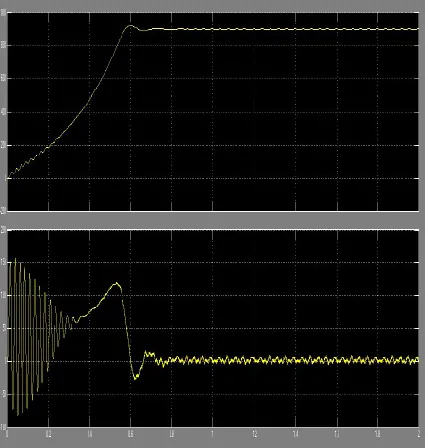
Available at http://internationaljournalofresearch.orgFigure 4. N-T Curves for 50Hz Frequency
V. CONCLUSION
The model simulation of a nine level inverter fed induction motor drive is done by using Simulink. This multilevel inverter generated very less Total Harmonic Distortion then compared to that classical inverters. Form this model simulation of nine level inverter fed induction motor system we measured the voltage, current waveform, and we observed speed and frequency spectrum is obtained. The proposed inverter can be used in industrial to adjust the speed drivers are require to save the energy then the system have very less harmonic losses.
REFERENCES
[1] Chunmei Feng and Vassilions G Agelidis (2000) On the Comaprison of fundamental and High frequency Carrier based techniques for multilevel NPC Inverters. IEEE PES Conf. 2, 520- 525.
[2] Golubev AN and Ignatenko SV (2000)
Influence of number of stator winding phases on noise characteristic of an asynchronous motor. Russian Electrical Engg. 71 (6)41- 46.
[3] Gopukumar K, Biswas SK, Satishkumar S and Joseph Vithyanthil (1984) Modified current
source inverter fed induction motor drive with reduced torque pulsation. IEEE Proc. 313 (4), 150-164.
[4] Haoran Zhang, Annette Von Hounne, Shaoan Dai et al. (2000) Multilevel inverter Modulation schemes to Eliminate Common Mode Voltages. IEEE Transaction on Industry Applications. 36, 1645-1653.
[5] Juan Dixon and Luis Moran (2006) High-Level Multi-step Inverter Optimization Using a Minimum Number of Power Transistors. IEEE Transactions on Power Electronics. 21, (2), 330- 337.
[6] Mohapatra. KK, Gopukumar K, Somashekhar VT and Umanand L (2002), A Modulation scheme for six phase induction motor with an open-end winding. 25th Annual Conference IECON 02 Spain. pp: 810-815.
[7] Muhammad H Rashid (1996) Power
Electronics Circuits Devices and Applications. Second Edition, PHI, New Delhi. pp: 566 – 572.
[8] Shivakumar E.G, Gopukumar K, Sinha S.K and Ranganathan V.T (2001) Space vector P WM control of dual inverter fed openend winding induction motor drive. IEEE APEC Conf. 1, 399 - 405.
[9] Somashekhar V.T and Gopukumar K (2003) Three level inverter configuration cascading two two-level inverter. IEE Proc. Elect. Power Applications.150 (3), 245-254. 10. Thomas M Jahns (1980) Improved reliability in solid state ac drives by means of multiple independent phase drive units. IEEE Trans. Ind. Appl. 16 (3), 321-331.
[10] Tolbert L, Peng F and Habetler T
c e-ISSN: 2348-6848, p- ISSN: 2348-795X Volume 2, Issue 11, November 2015
International Journal of Research (IJR)
Available at http://internationaljournalofresearch.org[11] Zhong DuLeon, M. Tolbert, and John
N. Chiasson, (2006) Active Harmonic
Elimination for Multilevel Converters. IEEE Transactions on Power Electronics. 21 (2), 459-469.
P. VaraprasadReddy was born on 1988. Received his B.Tech degree from JNTU, Hyderabad, India in 2009 and M.Tech degree in Power Electronics and Electrical Drives in 2012 from J.N.T.University, Anantapur, India. He has the teaching experience of 4 years. His areas of interests are Power Electronic Drives and Renewable Energy Sources.
K.J.SANTHOSH KUMAR M.tech (power Electronics and Electrical drives) pursuing VIGNANA BHARATHI INSTITUTE OF