MECHANICAL DESIGN AND CONSTRUCTION QUALIFICATION
PROGRAM ON ITER CORRECTION COILS STRUCTURES.
A. Foussat1, Wu Weiyue2, Wei Jing2, Du Shuangsong2, S. Sgobba4, Li Hongwei3, Paul Libeyre1, Cornelis Jong1, Kamil Klofac1, Neil Mitchell1
1ITER Organization, Route de Vinon sur Verdon, 13115 Saint Paul Lez Durance, France 2Academy of Science Institute of Plasma Physics, PO 1126, Hefei, Anhui, China -230031
3China International Nuclear Fusion Energy Program Execution Center, Ministry of Science and Technology, 15B Fuxing Rd.,Beijing, China 100862
E-mail of corresponding author: [email protected]
ABSTRACT
The ITER Magnet system consists of 4 main coils sub-systems, i.e. 18 Toroidal Field Coils, a Central Solenoid, 6 Poloidal Field Coils and 3 sets of Correction Coils. ITER fusion project has selected the stainless steel 316LN as main material for the magnet structure. The CC contribute to reducing the range of magnetic error fields created by imperfections in the location and geometry of the other coils used to confine, heat, and shape the plasma. During plasma operation, a large number of loading condition scenarios have been considered and structural analysis performed on key items like Cable-In-Conduit Conductor and the coil case. The results obtained are used for both static and fatigue structural assessment defining the present baseline design. For the construction of the structural cases, welding techniques such as GTAW (Gas Tungsten Arc Welding) and techniques resulting in low distortion and shrinkage like EBW (Electron Beam Welding) or Laser Beam Welding (LBW) with filler metal wire have been selected. Those methods are considered for future qualifications to guarantee proper weld parameters and specified weld properties. In order to determine the strength and fracture toughness of 316LN stainless steel welds with respect to design criteria, some mechanical tests are been carried out at 7 K (or 77 K), and room temperature.
INTRODUCTION
The large superconducting magnets of ITER fusion reactor [1] (figure 1.a) like ITER Correction coil system require structural cryogenic materials to withstand the applied cyclic electromagnetic loads on magnet cases and cable in conduit jackets up to 6 x 10⁴ cycles at 4.2 K. The industrially available nitrogen-bearing type 316LN austenitic stainless steel shows the expected increase of strength at 4 K. Nitrogen stabilizes the austenitic phase. The Correction Coils (CC)employ Cable-In-Conduit Conductors (CICC) with a 316L stainless steel conduit which encloses a Niobium Titanium (NbTi) superconducting cable serving the dual purposes of distributed structural support and containment vessel for the forced flow of liquid helium at 4 K. The manufactured glass epoxy resin impregnated conductor winding pack is embedded into a 316LN structural case sealed by a closure weld.
The intrinsic cyclic loading behavior of CC makes the fracture an important failure mode compared to plastic yielding. At those cryogenic temperature the limiting of stress peaks through local plasticity is less extensive than at Room Temperature (RT) and secondary stresses have lower allowable than at higher temperatures. Some intensive FE analysis of key structural items have been implemented to support the design of CC. A development test program is deployed in collaboration with the main coil supplier, the Chinese Institute of Plasma Physics (ASIPP, Hefei) and the Chinese domestic agency (CNDA, Beijing) in order to characterize the mechanical properties of base material and weld joint at cryogenic temperature.
THE SYSTEM OF ITER ERROR FIELD CORRECTION COILS
magnet system [3]. It consists of 18 coils grouped within three sets of superconducting coils (top, side and bottom) supplied by a nominal current of 10 kA and distributed poloidally as shown in Figure 1 to provide control of several magnetic error field modes.
Fig. 1. a) Cut view of ITER tokamak fusion plant reactor
b) Layout of CC system
The 12 bottom and top planar EFCCs respectively named BCC and TCC and arc-shaped are 7 m long and 2.8 m wide. The 6 Side EFCCs are three dimensional curved coils with 8.3 m length and 7.2 m width.
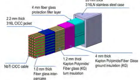
The major parameters of the EFCC system are listed in Table 1. Each coil consists of winding pack of pancakes. It uses a NbTi CICC with 35% void fraction supplied by supercritical helium at 4.5 K and 0.6 MPa. The Side EFCC have 20 turns while the BCC and TCC have both 32 turns (see figure 2).
The CICC of the CC contains 300 NbTi superconducting strands with a 3x4x5x5 cable strand pattern wrapped in 0.08 mm thick stainless steel tape and swaged in a 19.2 mm x 19.2 mmsquare 316L 2.2 mm thick jacket.
Fig. 2 Exploded view of the internal structure of EFCC winding pack
The main winding dimensions are summarized in table 1 below.
Table 1: Key parameters of the ITER Error Field Correction Coils
Coil case 20 mm thick 316LN stainless steel wall
Conductor NbTi Cable in conduit Conductor, AISI316L stainless steel jacket 19.2 mm x 19.2 mm
Turn insulation 1.2 mm thick Polyimide/glass fiber/epoxy Ground insulation 4 mm thick Polyimide/glass fiber/epoxy
Total cross section BCC/TCC SCC
Winding pack
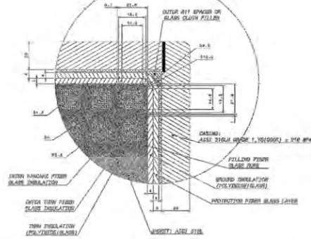
The square 316L material jacket is wound and shaped on automatic synchronized winding table and wrapped with interleaved multi-layered fiber glass / polyimide insulation system. The final winding pack includes the conductor, its turn insulation, the inter layer insulation, and the corner roving filler to be further monolithically vacuum pressure impregnated (VPI) with dedicated DGBE-F resin epoxy thermoset as shown in figure 3.
Fig. 3 Detailed cross section of the EFCC winding pack into the structural case
Fig. 4 View of BCC and TCC supported onto Toroidal field coil case
Structural case
A 20 mm thick wall case made of high strength 316LN stainless steel material provides the required stiffness to the coils in order to react the large electromagnetic loads attached with a limited number of supports to the Toroidal case. The composition analysis of the 316LN heat used to produce the samples tested in the present campaign is shown in table 2. Once the winding is inserted into the case, the latter is closed by EBW or LBW and finally further epoxy impregnated using the Vacuum Pressure Impregnation (VPI) process. Each individual EFCC is supported by prestressed clamp attached to the main Toroidal field cases as shown in figure 4 aimed at withstanding the electromagnetic loads and to accommodate for the TFC deformation due to out of plane and radial movements during operation by adopting a sliding interface type.
Table 2. Heat analysis (weight percent) of the 316LN sample material used in the present campaign of tests
Steel C N Mn Si P S Cr Ni Mo Nb
316L N
0.013 0.161 1.55 0.49 0.016 0.001 16.48 13.32 2.12 <0.01
Fracture toughness of 316LN at cryogenic temperature
High toughness is achieved in 316LN by controlling the purity and composition. Simon and Reeds [4] derived the 4 K fracture toughness (MPa√m) of 316LN steels as a function of Nickel content (weight %), yield strength (YS, MPa) at 4 K and inclusion spacing (λ, mm) according to relationship KIC(J) = 150 - 0.314 YS + 16.6 [Ni] +2300 λ, where λ is defined as n-1/2 and n is the number of inclusions per mm2 which amounts to 6430 for ITER material specification. In order to achieve a higher inclusion spacing an additional Electroslag remelting (ESR) processing might be considered offering an advantage with respect to simple primary melting in Electric Furnace (EF) followed by a decarburization process.
ITER CC STRUCTURAL DESIGN AND CRITERIA
The CCs operate at 4 K. Austenitic stainless steel provides increased yield and ultimate strength at this temperature compared to RT. Since the electromagnetic loads applied are cyclic the fatigue resistance is a relevant failure mode compared to plastic yielding. One of the main operation characteristic of CC and fusion magnets in general is that the in-service inspection of the magnets is not possible. However, for LEFM the criteria “defect penetrates the wall thickness” is used which means for the conductor jackets leakage before failure is an option.
The correction coil structures involve medium size material thicknesses, up to 30 mm, which include structural welds and undergo high stresses. The structural supports include some bonded non-metallic impregnated low voltage insulation materials especially used in compression for transmitting loads. The non uniform electromagnetic loads cause multi-axial stress systems, in conjunction with contact interfaces, which requires FE analysis for resolution.
Loading scenario
The main structure of magnets such as CC is submitted to. thermal loads during their cool down from 300 K to 4 K which can induce thermal stresses due to differential thermal contraction. The electromagnetic loads induced on structures during normal, pulsed operation of the tokamak machine are experienced as a result of the currents in the CC windings, interacting with the background magnetic fields. The electromagnetic load structural fatigue assessment is performed over the complete magnets reference scenario with plasma currents of 15 MA. The structural static assessment on correction coils is considering the worst case of both 15MA and 17MA scenario. A typical plasma scenario is characterized by some key event like Initial Magnetization (IM), Start of Burn (SOB), End of burn (EOB) [6].Resultant forces or moments on CC case and winding pack are transmitted through support structures attached to the toroidal coil case undergoing out of plane and radial deformations.
Static analysis criteria
As at cryogenic temperatures the ratio UTS/YS, where UTS is the Ultimate Tensile Strength for 316LN annealed plate material, is around 1.5 compared to 2.5 at 200 °C, also the UTS shows serration. For this reason, only the yield stress is used to define the limit design stress Sm as equal to 2/3 of yield stress in ASME. The main structural criteria on CC structural components such as the CICC jacket are summarized in table 3 below.
Table 3: Design limit and allowable static stresses
Level A service Limit
Limit stress [Mpa] Primary membrane stress (Pm) [Mpa]
Primary membrane + Bending stress (Pm + Pb) [Mpa]
Primary + Secondary stress
(P + Q) [Mpa] 316LN Sm = 2/3 * Sy
466
≤ 1.0 Km.Sm 466
≤ 1.5 Km.Sm 700
≤ 2.0* Km.Sm 933
Insulated 316L 466 ≤ 1.0 Km.Sm 466
≤ 1.3 Km.Sm 606
≤ 1.5 Km.Sm 700
Km are factors from 0.8 to 1.5 following section III, NB-3222, 3223, 3224. For the first three load categories depending on the base metal or welds without post welding treatment for different plate thickness, Km value is set at 1 in the above table.
Fatigue assessment criteria
The fatigue of ITER CC structural material is an important potential mode of failure due to the intrinsic cycling during operation. It has to be assessed inside the CICC jacket or the case materials. It could lead to leaks or breaks.
Three methods are currently exploited on ITER magnets, especially for CC structural members:
- The fatigue life assessment is based on the standard stress approach using reference SN curve at 4 K (R= -1) and a modified Goodman diagram for mean stress is used to evaluate non-planar flaws in larger components. A safety factor of the most conservative of either a factor of 2 on stress or 20 on cycles is applied to the converted operating fatigue stresses.
- The fatigue crack growth rate (da/dN) is based on Linear Elastic Fracture Mechanics (LEFM) which assumes an initial defect size and applies a safety factor on the predicted lifetime, defect size, and the fatigue stress intensity K which should be less than KIC /1.5 for Level A criteria.
The main specifications of yield and fracture toughness defined for base metal in table 4 (factors for welds are included in the design criteria) are based on the minimum material properties measured as part of the generic material qualification specified in the procurement packages.
Table 4: Static requirements at 4K for correction coil stainless steel case material classes (as forgings and plates) Name of material Temp. Young’s Modulus (GPa) Yield Strength (MPa) Ultimate Tensile Strength (MPa) Elongation at Failure (%) Fracture Toughness, KIC
(MPa m1/2)
316LN 300K >190 >250 >480 >35
(target: 40)
N/A
<7K >205 >700 >1000 >35 >180
GLOBAL ANALYSIS
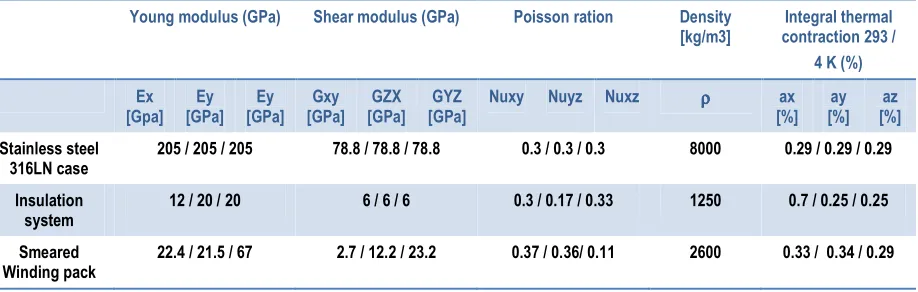
For the purpose of simulating the mechanical behavior of the CC magnet system, a three dimensional finite element ANSYS V12.1 global model and some detailed sub-modelled segment including the structural case, winding pack, insulation have been developed using solid brick elements for analysis of high stress regions. As shown in Fig. 5, the solid element model of BCC represents a 1/6 symmetry section of the tokamak coil structure. The basic materials of the model include the nitrogen-bearing stainless steel 316LN, which was proposed for the ITER CC case structure and the winding pack conductor jacket. This global section of coil consists of composite components such as resin insulated metallic jacket material as shown with orthotropic smeared material properties, which were calculated from the FE analysis of the CICC and assigned to each element in accordance with the element coordinate system. Both detailed sub model real material and smeared properties are summarized in table 5.
Fig. 5. Three dimensional finite element model including the structural case, winding pack, insulation material
Table 5: Input mechanical properties at cryogenic temperature for FEA models Young modulus (GPa) Shear modulus (GPa) Poisson ration Density
[kg/m3]
Integral thermal contraction 293 /
4 K (%)
Ex [Gpa] Ey [GPa] Ey [GPa] Gxy [GPa] GZX [GPa] GYZ [GPa]
Nuxy Nuyz Nuxz ρρρρ ax [%] ay [%] az [%] Stainless steel 316LN case
205 / 205 / 205 78.8 / 78.8 / 78.8 0.3 / 0.3 / 0.3 8000 0.29 / 0.29 / 0.29
Insulation system
12 / 20 / 20 6 / 6 / 6 0.3 / 0.17 / 0.33 1250 0.7 / 0.25 / 0.25
Smeared Winding pack
Boundary and Load conditions
During a plasma scenario some pairs of EFCC coils are ramped up with a maximum current rate of 2 kA/s to a 10 kA current flattop of 400 s then ramped down to zero current. This magnet configuration implies that non-uniform or opposite currents in the correction coil system can flow and interact differently with background magnetic field. Therefore, the worst case EFCC operating scenarios have been carefully investigated in order to find the maximum electromagnetic loads conditions resulting in linear forces as shown in figure 6. The actual distribution of forces per unit length of winding pack is non-uniform and reaches peak values up to 0.3 MN/m.
Static structural assessment results
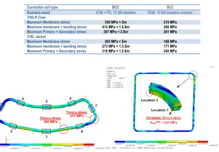
The linearized stress components (membrane, membrane plus bending) of high Tresca stress region into cases and CICC jackets material have been analysed according to the structural design criteria as summarized in table 6 below.
Table 6: Linearized Tresca stress in EFCC structural stainless steel members versus allowable stresses.
Fig 6. a) Overall Tresca stress on the BCC casing (EOB+PD, 17MA). b) Tresca stress on the SCC casing (SOB, 15 MA Baseline)
Correction coil type BCC SCC
Scenario event EOB + PD, 15 MA baseline SOB, 15 MA baseline scenario
316LN Case
Maximum Membrane stress 309 MPa < Sm 219 MPa
Maximum membrane + bending stress 412 MPa < 1.5.Sm 260 MPa
Maximum Primary + Secondary stress 397 MPa < 2.Sm 261 MPa
316L Jacket
Maximum Membrane stress 265 MPa < Sm 168 MPa
Maximum membrane + bending stress 273 MPa < 1.3.Sm 171 MPa
Fig 7. a) Local Tresca stress on the BCC casing (event EOB+PD, 17MA) b) Local Tresca stress on the SCC CICC Jacket (event SOB, 15 MA)
Fatigue structural assessment of casing
The maximum equivalent alternating stress intensity has been calculated over a complete scenario and compared to the zero mean stress fatigue S-N curve of 316LN base material measured at 4 K by Hamada et al. [7] in order to estimate the corresponding life cycle. As already mentioned, a safety factor of 2 on stress or 20 in number of cycles is applied to the experimentally determined curve, whichever is the most conservative. A residual stress of 50 MPa is considered as a reasonable assumption on base metal produced by hot processing methods. A shown in table 7, the equivalent Goodman principal stress range calculated in the base material is kept well below 50 % of the allowable design stress range Srf ) of 820 MPa corresponding to the stress amplitude limit of 410 MPa for a 6x10⁴ lifetime cycles. The UTS of 316LN at 4 K is 1200 MPa.
Table 7: Linearized Tresca stress in structural members versus allowable stresses.
CC BCC SCC
Scenario events IM and EOB+PD ,
15MA scenario
IM and SOB, 15 MA scenario 316LN Case
Principal Stress range ∆∆∆∆S1 224 MPa 100 MPa
Mean stress Smean 167 MPa 236 MPa
Equivalent Stress range Seq
(Goodman)
260 MPa < Srf 125 MPa < Srf
316L Jacket
Principal Stress range ∆∆∆∆S1 123 MPa 77 MPa
Mean stress Smean 114 MPa 219 MPa
Equivalent Stress range Seq
(Goodman)
136 MPa < Srf 94 MPa < Srf
A fatigue crack growth rate analysis based on Linear Elastic Fracture Mechanics (LEFM) assessment for the SS casing and the CICC jacket material is performed with a safety factor of 2 on defect size, a factor of 1.5 on fracture toughness and 2 on cycles. This approach is valid for design purposes as long as the crack-tip plastic zone remains in the regime of small scale yielding. The stress concentration factor relationship (1) allows the critical semi-elliptic crack size ac to be assessed for fracture under cycle loading of large thickness by equating K with
KIC/1.5 [8].
(1)
and an exponent m = 3.02. The design lifetime of 6 x 10⁴ cycles requires an initial crack size a of 1.9 mm, equivalent to a flaw size of 27 mm2, well within the non-destructive inspection capabilities.
Fatigue assessment of Helium inlet
Each EFCC winding incorporates up to ten helium supply oblong inlets pipe connected through full penetration TIG welds to the 2.2 mm thick stainless steel jackets. The hoop stress developing into the winding pack of coils submits the weld toe to tensile and shear stress which needs to be assessed against fatigue limits. As shown in Figure 8b, the tresca stress contour satisfy all static criteria as defined in table 3. Unlike the standard ASME III NB3200 fatigue design procedure based on small specimen data, the European standard EN 13445-3 approach derived from IIW recommendations [10] is based on statistical fatigue curve tests of different weld configuration, execution and geometry of real components. For cryogenic applications test data at 4 K are scarce. One route is first to compare plain material performance at RT [11] and 4K [12], and use this factor to modify a weld RT curve to create a 4K weld curve. This provides a ratio of alternating stress for 316LN at 6x10⁴ life cycles of [Sa_4K/Sa_300K] = 1.86. The weld fatigue curves at cryogenic temperature will experience similar fatigue behavior than observed at RT with respect to unwelded material due to the stress concentration factors of the component. Those categorized weld fatigue curves are based on representative experimental tests which include the effect of local stress concentrations due to the geometry of the welds, residual stresses, geometrical weld imperfections, access for NDT inspection. The helium inlet full penetrated weld is similar to the FAT-63 class weld fatigue curve series as defined in EN 13445-3 standard allowing a stress range of 204Mpa at 6x10⁴ cycles at RT, which corresponds to a allowable stress range of 380 MPa at 4K.
Fig.8.a) Reference JSME S-N curve of 316LN hot rolled plate base material at 4K with FAT extrapolation of weld fatigue curve.[12]
Fig.8.b) Tresca stress range contour on helium inlet weld toe.
The hot spot stress approach as defined by S.J. Maddox [13] and E. Niemi et al. [14] at a distance of 0.5 and 1 time the wall thickness, respectively, extrapolates the maximum geometrical hot spot stress range in CICC jacket of 320 MPa occurring in service at the weld toe where crack is likely to initiate on the helium inlet joint. This value has to be compared to the corresponding allowable stress range on figure 8.a that is 2 x 190 = 380 MPa which satisfies the criteria of 6.104 cycle lifetime.
Statistical approach Helium inlet prototype fatigue test
In order to confirm the fatigue analysis on correction coil inlet welds and the mode of failure, some cyclic axial testing on a full scale inlet assembly will be performed at the 4 K service temperature. A statistical analysis approach of Fatigue Test data is used to derive safe life factors as described in IIW note [15]. This method is used to define a minimum test cycle Nt to reach the design life Nd within a certain level of confidence for the given weld structure as expressed in equation (2).
, (2)
where Nt is the achieved life from a test of single or several samples, Nd is the design life of helium inlet weld, σd is standard deviation of logND, n the number of tests, A and B variables defining level of confidence.
mean, i.e 3 for a 99.86% probability of survival. The relation (2) becomes and yields a test life factor of 9.06 which means that for a design life of 60,000 cycles, the geometric mean life to failure from two test samples needs to be greater than 540,000 cycles. This value drops to 474000 cycles with 3 test samples. Special care on the weld cap to reduce toe angle and radius can be effective to increase fatigue lifetime.
First structural test results and test program on base material and welds
The qualification program of base material and welds at RT and 4.2 K on CC includes characterization of test specimens according to ISO 15614-1:2004 standard and specific requirements related to cryogenic characterization as summarized in table 8. The fabrication of CC cases involves low distortion and shrinkage welding techniques like EBW or LBW with filler for the final casing closure and Narrow Gap GTAW (NG-GTAW) welding on the casing sub parts assembly. All those processes target the quality acceptance level B following EN ISO 13919-1 for beam welding and ISO 5817 for arc welding. A prequalification program is set by ITER and CERN to characterize comparatively the mechanical properties of selected welding processes.
Table 8: Qualification tests on CC material and welds according to ISO standard and ITER requirements
ND and destructive tests on base material ND and destructive tests on Welded joints
• Microstructural observation: grain size, inclusion rate (ASTM E45 method D), delta-ferrite content, • Hardness (ISO 6506-1, ISO 6507-1)
• UT (S3/E4 following EN 10307)
• Tensile properties at RT, longitudinal and transversal (EN 10088-2, EN 10002-1)
• Tensile properties at 4.2 K, longitudinal and KIC (J) at 4.2 K, longitudinal and transversal (ASTM E 1820) • FCGR at 4.2 K, longitudinal and transversal to fibers • S-N curves at cryogenic temperature for the material shall be obtained for every heat according to JIS Z 2283 or equivalent.
• Visual (VT): EN 970, Visual examination
• Ultrasonic (UT): EN 1714, Ultrasonic testing of welded joints • Gammagraphic (γγγγ-RT): EN 1435, Radiographic examination
of welded joints
• Examinations, surface crack detection (PT): EN 571-1, Non-destructive testing. Penetrant testing.
• Micro- and macro-structural (EN 1321) observations, hardness profiles (EN 1043-2)
• Transversal tensile tests at RT (EN 895)
• Combined FCGR and KIC (JIC) tests (ASTM E 1820) at 4.2 K • S-N curves at cryogenic temperature on welds according to
JIS Z 2283 or equivalent.
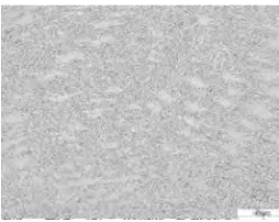
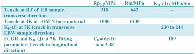
The first test results of tensile strength and FCGR characterization on EBW 316LN butt joint samples of 20 mm of thickness have been obtained at RT and 4.2K. Macro and microstructural pictures of the weld bead are shown in Fig. 10. Fig. 11 shows the sample removal scheme and first FCGR results. The tensile strength and Compact Test (CT) FCGR 316LN EBW specimens (machined at transverse and longitudinal weld directions, respectively) are machined according to ISO15614-1 as shown in figure 11.a) in a 20 mm thick welded plate. The calculated fracture toughness KIC (J) at 7 K (see table 10) for ductile fracture through the J-Integral test characterization according to ASTM 813 are above the specified minimum value of 180 MPa√m. A FCGR Paris law curve was measured at 4 K in the longitudinal weld direction as shown in the curve on figure 11.b). The fitting parameter of the Paris law are shown in table 9.
Fig. 10.a) Cut view of Electron beam 20 mm thick 316LN butt joint weld sample with back protection strip,
Figure 11 a) test specimens layout in EB welded plates according to ISO15614-1
b) Comparison of FCGR da/dN measured curves at 4K between 316LN EB weld sample and ITER 316LN extruded solution annealed base material [Reference from Dr Nyilas].
Table 9: Results on EB weld sample of tensile tests (RT), fracture toughness and FCGR at 4K
Rp0.2/MPa Rm/MPa KIC (J) / MPa/√√√√m
Tensile at RT of EB sample, transverse direction
318 642 -
Tensile at 4K of 316LN base material 1080 1430 -
KIC(J) at 7K (crack in transverse
EBW sample direction)
230 to 244
FCGR and KIC (J) at 7K, fitting
parameters ( crack in longitudinal direction)
C0 = 6e-10
m = 3.38
189
CONCLUSIONS
The system of ITER EFCC and its structural design have been presented as a common design approach on superconductive magnets. The ITER Magnet structural Design criteria in static and fatigue derived from RCC-MR2007, ASME BVP codes applied on coil structural members at cryogenic temperature were highlighted. The structural assessment over the reference ITER current scenario on global and local models of the CC winding pack and ITER CC case has shown that both static and fatigue criteria are satisfied: peak intensity Tresca stress is kept below the allowable stress as specified in ITER Magnet design criteria and the fatigue life beyond the design life cycle during the reference plasma scenario operation time. The lifetime assessment on key components such as helium inlets is investigated based on 316LN base material reference S-N fatigue data at 4 K and fatigue code methodology based on weld class fatigue curves. A statistical approach to determine the fatigue acceptance test data is considered to derive the expected number of test cycles on real component size. Some first mechanical tensile tests and FCGR on EBW butt joints confirm that the tensile strength and fracture toughness values are kept well within the EFCC mechanical design requirements.
ACKNOWLEDGEMENTS
The author would like to acknowledge especially the technical support or fruitful discussion with S. Atieh and G. Favre for CERN, A. Nyilas for CEME. The procurement task arrangement of ITER EFCCs is with Chinese Domestic Agency and the main responsible supplier is ASIPP Chinese institute,
DISCLAIMER
The views and opinions expressed herein do not necessarily reflect those of the ITER.
[1] N. Mitchell et al, “The ITER Magnet System”, IEEE Applied Superconductivity Conference, Vol.18, 2008, pp. 435 – 440
[2] A. Foussat et al., From Design to Development Phase of the ITER Correction Coils”, IEEE Applied
Superconductivity Conference, Vol XX, 2011
[3] N Mitchell, ITER Design Description Document, DDD 11 ITER_D_22HV5L v2.2, Private communication, Section 2.2
[4] R. P. Reed and N. J. Simon, “Design of 316LN-Type Alloys” Adv Cryo. Eng. Materials, vol 34, (1988), 165-172
[5] C. Jong, ITER Magnet Structural Design Criteria Part I, ITER Private communication Private communication , ITER_D_2FMHHSv.
[6] N Mitchell, ITER Reference Scenario 15MA, 17MA, IDM 2FTVKV, Release 1.10
[7] Hamada K., Nakajima H, Kawano K., ” Demonstration of full scale JJ1 and 316LN fabrication for ITER TF coil structure”, Fusion Engineering and Design 82 (2007) 1481–1486
[8] R.I Stephens, Metal fatigue in Engineering, chapter 6, ”Fundamental of LEFM and applications ot fatigue crack growth”, Wiley edition.
[9] A. Nyilas, Design Requirements and Guidelines Level 1 (DRG1), ITER Structural Material Database Article 2. Metallic Material Database, Annex 3. Final Report on ITER Coil Casing and Intercoil Structures (FzK), July 2000
[10] A. Hobbacher, IIW document Fatigue Recommendations, IIW-1823-07/XIII-2151r4-07/XV-1254r4-07, “Recommendations for fatigue design of welded joints and components”, International Institute of
Welding, December 2008.
[11] J.P. Strizak, Fatigue properties of type 316LN stainless steel in air and mercury, Journal of Nuclear
Materials 343 (2005), 134–144
[12] JSME, "Codes for Fusion Facilities - Rules on Superconducting Magnet Structure -", JSME S KA1-2008 (2008)
[13] S.J. Maddox, Recommended Hot-Spot Stress Design S-N Curves for Fatigue Assessment of FPSOs, Proceedings of the Eleventh (2001) International Offshore and Polar Engineering Conference Stavanger, Norway, June 17-22, 2001
[14] E. Niemi, W Fricke and S. Maddox: 'Fatigue analysis of welded components: Designer's guide to the structural hot-spot stress approach', Woodhead Publishing, 2006.