ISSN(Online): 2319-8753 ISSN (Print): 2347-6710
I
nternational
J
ournal of
I
nnovative
R
esearch in
S
cience,
E
ngineering and
T
echnology
(A High Impact Factor, Monthly, Peer Reviewed Journal) Visit: www.ijirset.com
Vol. 7, Issue 8, August 2018
Design and Analysis of Suspension and
Steering system along with the Wheel
Assembly of a BAJA ATV
Shripad Mane
Research Scholar, Sinhgad Academy of Engineering, Pune, India
ABSTRACT: A BAJA is an ATV(All Terrain Vehicle) which is known to be manufactured by inetrnational teams and also college students. This vehicle is used for competing in inter-collegiate competitions at national and international level. This article discusses the design and analysis of Suspension system, steering system and wheel assembly particularly for ATV BAJA Vehicle.
The Article discusses various suspension systems, steering systems which are used in the vehicle, suggests the best possible system that can be used in the vehicle and conducts analysis on the system.
The article also gives a design example of the wheel assembly that can be used with the suggested Suspension and steering system The design is thought out keeping in mind the BAJA SAE Rulebook and the design adheres to the rules laid down by the rulebook.
.
KEYWORDS: Automobile, Suspension System, ATV, Steering, Wheel Assembly, BAJA
I. INTRODUCTION
The steering system is group of parts that transmit the movement of steering wheel to the front wheels. The objective of steering system is to provide directional control of the vehicle, to withstand high stress in off terrain conditions, to reduce steering effort and to provide good response from road to driver. When vehicle is being driven straight ahead, the steering system must keep it from wandering without requiring the driver to make constant corrections. Working of steering system is based on the four bar linkage mechanism in which different links move relative to each other and finally direct vehicle in particular direction
STEERING
Steering Geometry Design:
Steering system is as designed on the basis of Ackerman geometry in CAD software. This geometry has two pairs of turning links which reduces tyre wear. Traction is an important aspect in off road racing as compared to speed. Since Ackerman steering geometry gives high stability at lower speed therefore we choose Ackerman steering geometry. In the top view various design assumption such as track-width and wheelbase were added. In the design process of this subsystem the goal is to achieve a small turning radius and steering stability for off-road racing. The complete geometry was modelled in the software carried out to achieve maximum Ackerman percentage and minimum turning radius.
Steering Gearbox Selection:
ISSN(Online): 2319-8753 ISSN (Print): 2347-6710
I
nternational
J
ournal of
I
nnovative
R
esearch in
S
cience,
E
ngineering and
T
echnology
(A High Impact Factor, Monthly, Peer Reviewed Journal) Visit: www.ijirset.com
Vol. 7, Issue 8, August 2018
1) Simple in construction.
2) Contact between steering rack and pinion is free of play and internal damping is maintained.
3) Easy to operate due to good degree of efficiency.
4) Tie rod can be directly joined to steering rack.
Rack and steering gearbox is compact. The rack travel one and a half turn from lock to lock which allows good control of vehicle and good responding speed.
Rack and pinion
The steering ratio of 4:1 is achieved which means for every 4 degree rotation of steering wheel tires will be turned by 1 degree.The rack travels 8.89cm(3.5in) from lock to look to make the wheel turn.The front wheels configuration has a 3.5° camber angle and an 11˚ caster angle. The caster tends to drive the wheels forward, which makes it easier to maintain the car in a straight direction, also the inclination of the knuckle helps to reduce the turning radius to 2.408m, as shown in Figure
Turning radius
Design of Linkages:
Tie rod are required to transmit force axially. The material we choose isto which one side ball joint is attached and to other side rose joint is attached. The lengths of the tie rods for steeringassembly were found to be 15.81 inches using three instantaneous centre method and iteration. Simulations were done for correct tie rod lengthand to study bump steer effects.
The steering arm is very essential component causing pivoting motion on the application of steering effort and it is made up of EN 19.
Correct steering angle:
While taking turns, the condition of perfect rolling is achieved if the axes of the front wheels when produced meet the rear axis at one point. This is the instantaneous centre of the vehicle. The inner wheel deflects by a greater angle than the outer wheel. larger the steering angle, smaller is the turning
ISSN(Online): 2319-8753 ISSN (Print): 2347-6710
I
nternational
J
ournal of
I
nnovative
R
esearch in
S
cience,
E
ngineering and
T
echnology
(A High Impact Factor, Monthly, Peer Reviewed Journal) Visit: www.ijirset.com
Vol. 7, Issue 8, August 2018
circle. The steering angle of the inner wheel can have a maximum value of about 41.7˚ degrees. The geometry has been demonstrated in fig.
Manufacturing Process:
The steering rack and pinion assembly should be mounted to the frame first before any other modifications to the steering column are made. The required alignment of the steering rack is 94 mm backward of the wheel location to allow of necessary alignment with the tie rod arm points of rotation on the knuckle. Once this is accomplished the steering column and steering wheel may be aligned to allow for the best movement of the U-joint that transfers the rotation from one axis to another. The mount for the steering column should then be welded firmly in place at the correct angle and should allow a stress free and no bending situation for the steering wheel. If the steering rack allows for too much rotation, bump stops should be put in place to limit the travel of the rack and pinion joint. Once the steering wheel and the rack and pinion joint are aligned, the tie rods can be produced to allow for whatever toe-in tolerance is wanted. A shorter tie rod allows for a toe-in situation and a longer tie rod allows for a toe-out situation.
Steering specifications
Steering ratio 125.66mm/rev
Rack travel 5”
Front track width 50’’
Wheel base 56’’
Inner lock angle 51.87˚
Outer lock angle 30.28˚
Caster 11˚
Scrub radius 48.95mm
Static Toe 0˚
Rack length 14’’
Rack mounting height 370 mm
Turning radius 2.808m
ISSN(Online): 2319-8753 ISSN (Print): 2347-6710
I
nternational
J
ournal of
I
nnovative
R
esearch in
S
cience,
E
ngineering and
T
echnology
(A High Impact Factor, Monthly, Peer Reviewed Journal) Visit: www.ijirset.com
Vol. 7, Issue 8, August 2018
deformation
II. SUSPENSION SYSTEM
1. Need of Suspension System
The Baja vehicle is challenged to maneuver through different terrain conditions. The obstacles placed during competition and testing urge the need of four-wheel independence. These obstacles include telephone poles, railroad tracks, rock gardens, mud bogs, water, and jersey barrier drop offs. The suspension design should be strong enough to withstand impact loads and maintain contact of tire with ground at the same time. This led us to develop a system, with minimal weight and optimum strength.
2. Standard Systems
Most commonly, following types of suspensions were used:
Double Wishbone Type:
The double A-arm consists of two A-shape structures. The double A-arm allows for easy, independent adjustability of the camber and toe via the toe links and tie rod joints. Due to the double A-arm shape, the links are inherently strong from triangulation.
Trailing arm Type:
Trailing‐arm suspension consists of an arm connecting the frame and the wheel, with the arm in front of the
wheel so that it is “trailing”. This type of suspension is used on the rear wheels. The advantages to this suspension are that it allows for only the vertical movement of the wheel, which is ideal for the rear wheels, and it is light weight and compact.
Out of the above mentioned suspensions, double wishbone serves the purpose quite usefully. However, the inherent weight of trailing arm and no camber gain during upward travel makes it less of a preference. This made look for new options with lesser weight.
3. Objectives of Suspension System
The main objectives kept in mind while developing the design for suspension were as follows. They were chosen as most important from variety of requirements.
Fully Independent - wheels are in contact with the ground at all times.
Impact Loading - IRS must be capable of absorbing any loads faced in the competition.
Adjustability - ability to easily tune and adjust the suspension set up.
Drive-train Efficiency - competition rules limit the vehicle to 10 hp. System must limit power losses from the
ISSN(Online): 2319-8753 ISSN (Print): 2347-6710
I
nternational
J
ournal of
I
nnovative
R
esearch in
S
cience,
E
ngineering and
T
echnology
(A High Impact Factor, Monthly, Peer Reviewed Journal) Visit: www.ijirset.com
Vol. 7, Issue 8, August 2018
4. Determining Vehicle parameters
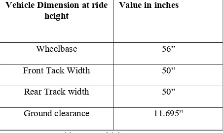
BAJA Competition rules were paramount while considering vehicle parameters. Smaller track-width helps in maneuverability and smaller wheelbase helped to reduce turning radius of vehicle. Following parameters were selected as basic vehicle dimensions.
Vehicle Dimension at ride height
Value in inches
Wheelbase 56”
Front Tack Width 50”
Rear Track width 50”
Ground clearance 11.695”
Table-4.1: Vehicle Parameters Following suspension system parameters were defined:
Suspension System Parameter
Value
Roll center height Front: 242.33 mm
Rear: 250 mm
Static Toe 0°
Caster 11°
KPI
Offset 8° 90 mm
Suspension travel in jounce Front: 7.057”
Rear: 6”
Suspension travel in rebound Front: 4.286” Rear: 1.98”
ISSN(Online): 2319-8753 ISSN (Print): 2347-6710
I
nternational
J
ournal of
I
nnovative
R
esearch in
S
cience,
E
ngineering and
T
echnology
(A High Impact Factor, Monthly, Peer Reviewed Journal) Visit: www.ijirset.com
Vol. 7, Issue 8, August 2018
5. Basics of Suspension system
Some basic terminologies are important to be cleared before going into design of system. 5.1. Caster
Caster is another useful feature that should be considered for the steering of the vehicle. In addition to being used to alter the camber when turning, it can enhance the damping of the suspension depending on how the shocks are set up. With caster, as the wheel is turned, the vehicle will gain camber. The camber gain is negative compared to the direction the wheel is turning and this is ideal. Caster can also improve the tendency for the wheels to self-center. Figure 6 shows positive and negative caster.
5.2. Kingpin Inclination
Kingpin inclination is defined as the angle at which kingpin axis is inclined to the vertical axis passing through the wheel center.
Kingpin angle affects the performance of the car when the wheels are steered. More the kingpin angle more the car will lift when steered.
When the kingpin axis is extended up to the ground, it intersects the ground at a particular point. The distance of that point from the center of wheel contact patch is called scrub radius. Scrub radius increases the wear of the tire but some amount of negative scrub radius is required so that the wheel purely rolls when steered.
Following figure represents relation between kingpin inclination, scrub radius and positive camber.
Figure-5.2.1: KPI and Camber 5.3. Camber
ISSN(Online): 2319-8753 ISSN (Print): 2347-6710
I
nternational
J
ournal of
I
nnovative
R
esearch in
S
cience,
E
ngineering and
T
echnology
(A High Impact Factor, Monthly, Peer Reviewed Journal) Visit: www.ijirset.com
Vol. 7, Issue 8, August 2018
Figure-5.3.1: Camber angle 5.4. Toe
The toe out configuration can be used to gain stability in a straight line. Additionally, toe out can compensate for the rolling tendency of the negative camber wheels. As an example of rolling tendency, as a spinning coin slows down, it tends to form a cone like shape. The coin wants to keep turning in the same direction to keep creating this cone like shape. This is called camber thrust and it is a type of twisting moment. Avoiding or reducing the rolling tendency is sought after because rolling tendency increases rolling resistance and wear on the wheels. Toe can be adjusted fairly easily by adjusting the lengths of the tie rods.
Figure- 5.4.1: Toe in and Toe out
III. FRONT SUSPENSION
3.1 Objectives of Front Suspension:
To achieve optimal camber compensation during wheel travel and cornering.There should not be toe change or at least adjustable toe change.Weight should be minimum.To avoid bump steer during wheel travel.To allow the driver to have complete vehicle dynamic control.
The suspension system is selected which satisfies all the above gals and allows packaging in compact space, with minimal weight.
ISSN(Online): 2319-8753 ISSN (Print): 2347-6710
I
nternational
J
ournal of
I
nnovative
R
esearch in
S
cience,
E
ngineering and
T
echnology
(A High Impact Factor, Monthly, Peer Reviewed Journal) Visit: www.ijirset.com
Vol. 7, Issue 8, August 2018
3.2 Strength of Links:
The material of links was selected keeping their strength under impact loading in mind. The lower control arm was designed using 1.65mm Thickness and 25.4mm OD. The upper control arm was designed using 1.2mm thickness and 25.4mm OD.
3.3 Geometry of Suspension linkages:
The main goal of fixing suspension geometry is that there should be optimum distance between roll center and center of gravity of body. The geometry is designed such that position of roll center is near to CG. The length of linkages, angle and pick-up points are identified. This is done by many iterations with help of ICR diagram.
Fig.6.3.1: Determining roll center
3.4 Simulation
Simulation is carried out in order to evaluate performance of suspension and steering under various conditions. The simulation is carried out in MSC ADAMS Car Software. The graphics of results are as follows
Fig.6.4.1:bump steer
ISSN(Online): 2319-8753 ISSN (Print): 2347-6710
I
nternational
J
ournal of
I
nnovative
R
esearch in
S
cience,
E
ngineering and
T
echnology
(A High Impact Factor, Monthly, Peer Reviewed Journal) Visit: www.ijirset.com
Vol. 7, Issue 8, August 2018
3.5 Finite Element Analysis of Front Suspension:
The Finite element analysis is important step in designing. Not only it helps validate design in term of safe loading but helps to determine points of extreme stress concentration.
Following graphics show FEA of Front suspension system elements.
Fig.6.5.1: Von-mises stress LCA
Fig.6.5.2: Deformation in LCA
IV. REAR SUSPENSION
4.1 H-arm type Suspension:
In the H-arm system, one end of the arm is connecting to two locations of the car body; another end connects to two locations of the wheel hub. The H-arm alone can limit 4 degrees of freedom, so it need another horizontal control arm to limit one more degree to make the whole system with 1 degree of freedom.
However the above design has non-optimal wheel movement trajectory, most automaker will not use such design without modifications. On the other hand, with proper design enhancements which creates variations of the H-arm system, superior handling performance can be achieved. In fact some of the luxury cars and high-end exotic sports cars use such design.
4.2 Strength of linkages:
ISSN(Online): 2319-8753 ISSN (Print): 2347-6710
I
nternational
J
ournal of
I
nnovative
R
esearch in
S
cience,
E
ngineering and
T
echnology
(A High Impact Factor, Monthly, Peer Reviewed Journal) Visit: www.ijirset.com
Vol. 7, Issue 8, August 2018
4.3 Geometry of suspension likages:
The geometry of rear suspension is designed such that as to get desired height of rear roll centre. This is achieved by performing many iterations with help of ICR diagram.
4.4 Finite Element Analysis of Rear control arm:
FEA of H- arm was performed to get results on stresses and deformation of linkages.
Fig.7.4.1: Von-misses Stress in H-arm
Fig.7.4.2: Deformation in H-arm
V. WHEEL ASSEMBLY
5.1 Introduction
ISSN(Online): 2319-8753 ISSN (Print): 2347-6710
I
nternational
J
ournal of
I
nnovative
R
esearch in
S
cience,
E
ngineering and
T
echnology
(A High Impact Factor, Monthly, Peer Reviewed Journal) Visit: www.ijirset.com
Vol. 7, Issue 8, August 2018
5.2 Analysis
Fig.1: Von-misses Stress in front hub
Fig.2: Deformation in front hub
Fig.3: Von misses Stress in rear hub
ISSN(Online): 2319-8753 ISSN (Print): 2347-6710
I
nternational
J
ournal of
I
nnovative
R
esearch in
S
cience,
E
ngineering and
T
echnology
(A High Impact Factor, Monthly, Peer Reviewed Journal) Visit: www.ijirset.com
Vol. 7, Issue 8, August 2018
Fig.5: Von misses stress in rear upright
Fig.6: Deformation in rear upright.
VI. CONCLUSION
Thus, we got to know about the various suspension and steering systems used in BAJA vehicle, got to know about their parameters and did analysis on a designed suspension, steering and wheel assembly components.
REFERENCES
1. Competition Car Suspension, Design, construction, Tuning, Allan Staniforth 2. Basics of Automobiles, Kirpal Singh
3. Fundamentals of Vehicle Dynamics, Thomas Gellespie 4. Milliken and Milliken Race car vehicle dynamics 5. Tune to Win, Carroll Smith