ISSN(Online): 2320-9801
ISSN (Print) : 2320-9798
I
nternational
J
ournal of
I
nnovative
R
esearch in
C
omputer
and
C
ommunication
E
ngineering
(An ISO 3297: 2007 Certified Organization)
Vol. 3, Issue 9, September 2015
Terrorist Scanner Radar with Multiple Object
Detection
Supriya Kunjir, Rajesh Autee,
ME Student, Dept. of Electronics and Communication, Deogiri Institute of Engineering and Management Studies,
Aurangabad, Maharashtra, India
Head of the Department, Dept. of Electronics and Communication, Deogiri Institute of Engineering and Management
Studies, Aurangabad, Maharashtra, India
ABSTRACT: The increasing requirement in the field of security at nation border leads to a demand for sensor network
beyond simple security applications. The detection of terrorist is an important obstacle to the improvement of the security at nation border. Manual screening or other security applications like Auto bomb blaster, Long range firing equipment, cordless transmitter and receiver are common in controlled access like in entry restricted area of nation border, but the problem with them is they are difficult to maintain. The purpose of this proposed system is to design more secure system based on radar sensor network for enhanced security at national border which can detect the obstacles coming into entry restricted area of national border. The system specifically aims the task of detecting exact kind of obstacles by means of ultrasonic radar sensor network and camera and provides count of them by using counter. This ultrasonic sensor network, counter and display unit is then coupled to the FM transceiver to get voice announcement at military base camp. Here attempt is made to develop a cost effective security system based on radar sensor network to prevent terrorism to a great extent.
KEYWORDS: Counter, Camera Radar, Ultrasonic transmitter, Ultrasonic receiver
I.INTRODUCTION
In this rapidly growing world security becomes an important and basic requirement in each and every place of the world. And as per the requirements technology has done great revolution in the field of security. Now a days, in response to the recent incidents of terrorism in the nation, it becomes necessary to design and develop an advance security system against terrorism for national border. Therefore here is attempt made to have security system for national border using ultrasonic sensor network, which helps to protect the nation against terrorism to a great extent. Project goal is to build a more sensitive security system which can prevents terrorism. The development of the system can be achieved by using ultrasonic radar. The set of ultrasonic transmitter and receiver sensors with camera is placed on motor assembly and being rotated by motor in 180º angle at entry restricted area of nation border. This sensor network and camera is then coupled to counter and display section, which will gives us the count of obstacle found by sensor network and display of images taken by camera into their scanning path. Further the entire system is coupled with FM transmitter and receiver to get voice announcement at military base camp to provide continues updates from border area. Due to the feature of image provision, we are able to take suitable control action against terrorist.
II. RELATED WORK
ISSN(Online): 2320-9801
ISSN (Print) : 2320-9798
I
nternational
J
ournal of
I
nnovative
R
esearch in
C
omputer
and
C
ommunication
E
ngineering
(An ISO 3297: 2007 Certified Organization)
Vol. 3, Issue 9, September 2015
targets, (ii) through wall radar imaging, (iii) radar tomography and detection of concealed weapon, and (iv) passive bi-static radar. Radar is widely used in the application of weapon detection against terrorism. Radar and in particular swept frequency radar is used for metallic object detection with microwave measurement system. A microwave measurement system for metallic object detection using swept frequency radar (Yong Li et.al2008) [2] presents a microwave measurement system for metallic object detection using swept frequency radar. This system reports on a 1-14 GHz swept-frequency radar system for metallic object detection using reflection configuration. The behavior of a number of metallic objects, in terms of their position, shape, rotation and multiple objects can be tested and analyzed using swept frequency response. The system working from 1 to 14 GHz has been set up to implement sensing of metal items at a standoff distance of more than 1 meter. By doing number of experiments, it can be found that the optical depths derived from the Fourier Transform of the power spectrum profile is in close relation with the relative location of the metallic objects like Guns and knives. Project review on ultrasonic distance measurement (Prakhar Shrivastava et.al 2014) [3] presents a device can measure distance in the range of 0.5m to 4m with the tolerance of 1cm. Distance measurement can be done by using ultrasonic sensors. A 40 KHz frequency signals transmitted by ultrasonic transmitter. Then, the ultrasonic receiver will measure the amount of time taken for a pulse of sound travel to a particular surfaces and return back reflected signals. After that, the circuit of AT mega microcontroller will calculate the distance based on the speed of sound at 25°C which an ambient temperature and also calculates the time. Then the results will be display on a LCD. The importance of the device is calculating accurate distance from any obstacle that we want to measure. Image segmentation of concealed objects detected by terahertz imaging (Sheeja Agustin et.al.2010) [4] presents a method for image segmentation of concealed objects detection by terahertz imaging. Terahertz radiation is emitted as part of the black body radiation from anything with temperatures greater than about 10 Kelvin. A reasonable penetration depth in certain common materials like cloth, plastic, wood, sand and soil can be perform by Terahertz waves. Therefore, THz radiation can detect concealed weapons since many nonmetallic, non-polar materials are transparent to this type of radiation (and are not transparent to visible radiation). In this system the multilevel thresholding method is applied to get initial segmentation of concealed objects in terahertz images .Then Gonzalez method and Gonzalez Improved methods are proposed to detect and segment concealed objects in terahertz images more correctly with specific shape.
Radar based automatic target system (Gavin Dingley and Clive Alabaster 2009) [5] presents the novel application of both dual tone CW and ISAR techniques to measure the position of a small high velocity projectile because it passes through a defined sensory virtual plane, therefore it forms basis for an automatic target detection. Systems that are commercially available operate using either acoustic or optical principles. The various technical problems associated with optical and acoustic automatic target systems has made the development of a radar based system desirable, as such a system will generally be more compact, capable of measuring both subsonic and supersonic velocity projectiles, and less influenced by the characteristics of the local environment. This contribution describes the work so far in developing a radar based targeting system for small targets. Terrorist scanner radar with military headquarter informing system (Rushikesh B. Kuasadikar et.al 2013) [6] presents a border security system which is mainly based on RADAR principle. In this paper the proposed system can detect only object within its working range but it is not possible to detect exact kind of object is been detected. As the system is not able to detect the exact type of object due to which it is not possible to take suitable control action. Firing action is taken as a control action. Sometimes the obstacle detected not required that much long time firing or sometimes it may not be enough. Problems like these can be occurs with the system because the system does not have any facility to capture the images of the objects being detect. Technology Focus [7] is the bulletin of defense research and development organization describes different radars with their technology and applications for defense area. In all these systems radar is used to detect objects which come into its working range. If the terrorists are not detected by any of the system, it is very prone that they could breach the countries border and can enter into the country which can result into many terrorist activities. So the proposed systemcan be helpful in avoiding terrorism in the country to a greater extent.
III. SYSTEM DEVELPOMENT
ISSN(Online): 2320-9801
ISSN (Print) : 2320-9798
I
nternational
J
ournal of
I
nnovative
R
esearch in
C
omputer
and
C
ommunication
E
ngineering
(An ISO 3297: 2007 Certified Organization)
Vol. 3, Issue 9, September 2015
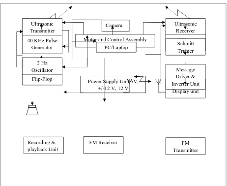
Further it coupled with message drive unit, FM transmitter and receiver for voice announcement. The camera images send to display section which is normally PC or laptop or any other display devices.
1)2 Hz oscillator and flip flop- 2 Hz oscillator is designed to produce oscillations which is required to make flip flop on and off. S-R flip flop is designed here to generate set and reset signals to the 40 KHz generator.
Figure. 1: Block Diagram of proposed system
2) 40 KHz pulse generator and counter- It generates 40 KHz of frequency on which ultrasonic transmitter works. The pulses of 40 kHz frequency generated by pulse generator are simultaneously counted by counter.
3) Ultrasonic transmitter and receiver- The pair of ultrasonic transmitter and receiver which works on 40 KHz frequency. Transmitter rotates continuously and transmits the frequency signals into it scanning path and when there is any obstacle comes into path the signals gets reflect. That reflected signals then receive by ultrasonic receiver.
4) Camera- Camera which is located with ultrasonic sensors also rotates continuously with sensor and use to capture images of detected obstacle and send them to display section.
5) Motor and control assembly- Motor is used to rotate ultrasonic sensors and camera in 180º and control assembly is used to change the direction of motor in forward and backward direction to maketotal scanning path of 180º
6) Signal Amplifier- The output of ultrasonic receiver is very weak due to the interference available in air. So to amplify these weak signals, signal amplifier is used.
Camera Ultrasonic
Transmitter
Ultrasonic Receiver
FM Receiver Recording &
playback Unit
FM Transmitter Power Supply Unit 5V,
+/-12 V, 12 V
Motor and Control Assembly
Counter& Display unit Flip-Flop
Counter 40 KHz Pulse
Generator
3 Stage Amplifiers
PC/Laptop Schmitt
Trigger
2 Hz
Oscillator Message
ISSN(Online): 2320-9801
ISSN (Print) : 2320-9798
I
nternational
J
ournal of
I
nnovative
R
esearch in
C
omputer
and
C
ommunication
E
ngineering
(An ISO 3297: 2007 Certified Organization)
Vol. 3, Issue 9, September 2015
7) Schmitt trigger- Schmitt trigger as a comparator is used compare the received signals to with reference signals. 8) Counter & display unit- It is used to count number of obstacle detected by ultrasonic sensors and display them on display unit.
9) Message driver unit, FM transceiver- Combine used to generate a message and transmit it to the military base camp using FM transceiver and play.
IV. PRACTICAL RESULTS
Ultrasonic transmitter transmits 40 KHz of frequency signals which reflects off from obstacle and then received by ultrasonic receiver. The receiver frequency calculation after detection of any obstacle is as below:
Frequency received by ultrasonic receiver is: Period of received signal is 11.40 µsec. F=1/T (1)
F= (2)
F=87.719 KHz
Here signal Amplifier is used for amplification of receivedsignals, therefore strength of received signal is greater than the transmitted one.The voltage at receiver circuit after obstacle detection is 11.80V.
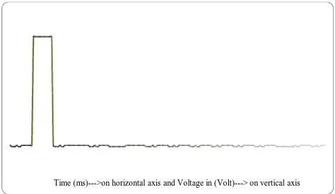
Output response of ultrasonic transceiver when there is obstacle into its scanning path.
Figure. 2: Two obstacle detected waveform
The wave forming figure 2 shows that output of ultrasonic transceiver when two obstacles come into its scanning path. It shows that positively going two high pulses when detects two obstacles into its scanning path. Normally its output is at lower voltage level approximately 6.8V to 7V and when it detects some obstacles into its path the voltage levelincreases positively up to 25.4V. It gives one high pulse for every new obstacle coming into its scanning path. The output shown in waveform above can also be verified by the counter output module attached to the sensor network.
ISSN(Online): 2320-9801
ISSN (Print) : 2320-9798
I
nternational
J
ournal of
I
nnovative
R
esearch in
C
omputer
and
C
ommunication
E
ngineering
(An ISO 3297: 2007 Certified Organization)
Vol. 3, Issue 9, September 2015
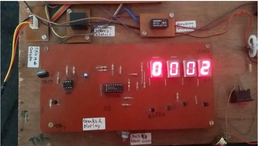
Figure 3: Counter output for 2 obstacle detection
VI. CONCLUSION
This system gives notification of any objects which makes entry to the restricted areason national border and also gives images of the concern objects. Object scanning, detection and image capturing is the heart of system which helps to prevent terrorism. Voice announcement gives alert to military of the nation.
REFERENCES
[1]Hugh D. Griffiths and Chris J. Baker, “Radar imaging for combating terrorism” Springer printed in the Netherlands, 2006.
[2] Yong Li et.al. “A Microwave Measurement System for Metallic Object Detection using Swept-Frequency Radar” Proc. of SPIE, vol. 7117, 71170K, 2008.
[3] Prakhar Shrivastava et.al, “Project review on Ultrasonic Distance Measurement” International Journal of Engineering and Technical research, ISSN 2321-0869, 2014.
[4] Sheeja Agustin A.et.al, "Image Segmentation of Concealed Objects detected by Terahertz Imaging," IEEE Conference on Computational Intelligence and Computing Research, 2010.
[5] Gavin Dingley and Clive Alabaster, “Radar based Automatic Target System” IEEE International WD&D conference, pp. 9781-4244-2971, 2009. [6] Rushikesh B. Kausadikar et.al, “Terrorist scanner radar with military headquarters informing system” International Journal of Computer Technology and Electronics Engineering vol. 3, March-April 3013.