ABSTRACT
TIPSUWAN, YODYIUM. Gain Scheduling for Networked Control System. (Under the direction of Dr. Mo-Yuen Chow.)
Performances of closed-loop control systems operated over a data network are typically
degraded by network-induced delays. Furthermore, the closed-loop control systems can
become unstable. The purpose of this research has been to develop a control methodology to
handle network-induced delay effects using optimal gain scheduling on existing controllers.
The proposed gain scheduling technique adapts controller gains externally by modifying a
controller output to enable the controller for uses over a data network. Since existing
controllers can still be utilized, the proposed methodology can reduce control system
reinstallation and replacement costs. First, the effectiveness of the proposed gain scheduling
technique on networked DC motor speed control using a PI (Proportional-Integral) controller is
investigated. Also, the concept of network traffic condition measurement to select optimal
controller gains is presented. Then, a middleware framework to measure network traffic
conditions on an IP network based on delays and delay variations and to modify controller
gains is described. Suggestion of using neural network in the gain scheduling scheme is also
given. Finally, the gain scheduling technique with the middleware framework is then extended
GAIN SCHEDULING FOR NETWORKED
CONTROL
SYSTEMby
Yodyium Tipsuwan
A dissertation submitted to the Graduate Faculty of North Carolina State University
in partial fulfillment of the requirements for .the Degree of
Doctor of Philosophy
Department of Electrical and Computer Engineering
Raleigh
2003
APPROVED BY:
~~~~~9~A
~
ii
BIOGRAPHY
Yodyium Tipsuwan was born in Chiangmai, Thailand. He received the B.Eng. degree (with honors) in computer engineering in 1996 from Kasetsart University, Bangkok, Thailand, and the M.S. degree in electrical engineering in 1999 from North Carolina State University, Raleigh.
After his graduation in the B.Eng., he joined the Department of Computer Engineering, Kasetsart University as an instructor to mainly teach digital system designs and microprocessor-based control systems in 1996, and has been awarded the Royal Thai Scholarship to continue his study in M.S. and Ph.D. degrees since 1998. During his M.S. study, he focused on intelligent control and its implementation. He is currently a Ph.D. candidate at North Carolina State University. His main interests are distributed networked control systems, mobile robotics, and computational intelligence. His current research topic is networked control over IP networks.
iv
ACKNOWLEDGMENTS
This dissertation could not be completed without many helpful suggestions and motivation from several faculties, friends, and my parents. First, I would like to express my utmost gratitude to my advisor Dr. Mo-Yuen Chow. Dr. Chow has spent his tireless effort and precious time to supervise, encourage, and inspire me on my research since I have been arrived at North Carolina State University. He has continuously educated and guided me from a person who was new in the research area to a person who knows a little more with inspiration to continue challenging research works. I would also thank to Dr. Douglas S. Reeves for his discussion and suggestion on computer network issues, Dr. James J. Brickley for his substitution in my preliminary examination, Dr. Griff L. Bilbro and Dr. Hamid Krim for the valuable comments on this dissertation at the final stages of my study.
In addition, I would like to express my deepest appreciation to my parents, Mr. Prasit and Mrs. Chamaiporn Tipsuwan, for their endless love, support, understanding, and encouragement, and my closest friends, Ms. Saowanee Lertworasirikul, Mr. Somsak Pakpinyo, and Mr. Rangsarit Vanijjirattikhan, for their encouragement and support on various things during my study, and many other friends that I could not mention them all here.
TABLE OF CONTENTS
LIST OF TABLES viii
LIST OF FIGURES x
CHAPTER I: INTRODUCTION 1
I. Networked Control Systems...1
II. Gain Scheduling...5
III. Neural Networks...6
IV. Middleware ...8
V. Gain Scheduler Middleware (GSM) ...10
VI. Overview of the Dissertation...11
References ...13
CHAPTER II: CONTROL METHODOLOGIES IN NETWORKED CONTROL SYSTEMS 17 I. Introduction...18
II. Overview of Networked Control System...20
III. Recent Networked Control Methodologies ...30
IV. Conclusion ...46
Acknowledgement ...48
References ...48
CHAPTER III: GAIN ADAPTATION OF NETWORKED DC MOTOR CONTROLLERS BASED ON QOS VARIATIONS 52 I. Introduction...53
II. Problem Formulation...58
vi
IV. Simulation Setups ...63
V. Conclusion ...72
Acknowledgement ...73
References ...73
CHAPTER IV: METHODOLOGY OF USING NETWORKED PI CONTROLLER GAIN SCHEDULING OVER IP NETWORK: PART I – FOUNDATION 75 I. Introduction...77
II. System Description...79
III. Parameterization for Gain Scheduling: Constant Network Delay ...85
IV. Conclusion ...95
Acknowledgement ...96
References ...96
CHAPTER V: METHODOLOGY OF USING NETWORKED PI CONTROLLER GAIN SCHEDULING OVER IP NETWORK: PART I – NETWORKED CONTROL ON ACTUAL IP NETWORK 99 I. Introduction...101
II. Parameterization for Gain Scheduling: Actual IP Network Delay ...101
III. Gain Scheduling Algorithm...109
IV. Case Study and Simulation Results...112
V. Conclusion ...119
Acknowledgement ...120
References ...120
APPENDIX FOR CHAPTER IV AND V: NEURAL-NETWORK-BASED GAIN SCHEDULING FOR NETWORKED PI CONTROLLER OVER IP NETWORK `122 I. Relationship approximation by neural network...122
CHAPTER VI: GAIN SCHEDULER MIDDLEWARE FOR MOBILE ROBOT
PATH-TRACKING OVER IP NETWORK 129
I. Introduction...130
II. System Description...132
III. A Case Study: Mobile Robot Path-tracking...134
IV. Use of GSM for Mobile Robot Path-Tracking Control over a Network ...140
V. Simulation and Experimental Results ...149
VI. Conclusion ...158
Acknowledgement ...158
viii
LIST OF TABLES
CHAPTER III
1. DC motor parameters...61
CHAPTER IV
1. DC motor parameters...83
2. βmax
( )
τ of the networked DC motor PI speed control system with respect to τ . ...913. Optimal β from optimization using (2) and (3) to approximate delays with w1=1.64902,
2 0.00833, 0.01395, 100, 10 3 f sec
w = w = M = t = : woc-(without constraint), wc-(with
constraint J1≤0.02, J2 ≤0.01, J3≤0.15), N/A-not available. ...94
4. Percentage error between the optimal β obtained by using (2) and (3) defined as βact and
the optimal β obtained by using denominator approximation defined as βapp from
simulations ...94
CHAPTER V
1. Destinations to measure RTT delays from ADAC Lab at NCSU, their location, and distance: www,lib.ncsu.edu, www.visitnc.com, www.utexas.edu, and www.ku.ac.th.102 2. Statistical measures (minimum, median, mean, and maximum) of RTT delays measured
from ADAC Lab at NCSU to www.lib.ncsu.edu, www.visitnc.com, www.utexas.edu, and www.ku.ac.th ...102
3. Optimal β with respect to η=0.01,0.02,0.03,0.04, and φ =0,0.001,0.002,...,0.009
obtained with w1=1.64902, 0.00833, 0.01395, 100, 10 w2 = w3 = M = tf = sec without
constraint...109
4. Cost J from the networked DC motor PI speed control system simulation with various η
5. Cost J from the networked DC motor PI speed control system simulation with various φ while holding η constant at η=0.0232 ...114
6. Cost J from the networked DC motor PI speed control simulation using pre-computed RTT
delays generated from (a) η=0.0005, 0.0001φ = . (b) η=0.0232, 0.0094φ = . (c)
0.0627
η= , 0.0002φ = , and (d) η=0.3150, 0.0058φ = ...115
7. Cost J from network DC motor PI speed control simulation using RTT delays from ADAC
Lab at NCSU to: (a) www.lib.ncsu.edu. (b) www.visitnc.com. (c) www.utexas.edu. (d) www.ku.ac.th ...117
APPENDIX FOR CHAPTER IV AND V
1. Mean-squared error from applying the testing set on neural networks with h=3, 5, 7, and
10...125
2. Costs J from network DC motor PI speed control simulations using RTT delays from
ADAC lab at NCSU to: (a) www.lib.ncsu.edu. (b) www.visitnc.com. (c) www.utexas.edu. (d) www.ku.ac.th. ...127
CHAPTER VI
x
LIST OF FIGURES
CHAPTER I
1. Networked control system data transfer...1
2. Altitude control system of airplane ...2
3. Remote control system of Mars rover...3
4. Comparison of robot tracks with and without network delay in the feedback control loop ...4
5. Block diagram of feedback control system with gain scheduling...5
6. Fundamental structure of a neuron...6
7. Multilayer feedforward neural network ...7
8. Fundamental structure of middleware...9
9. Basic structure of gain scheduler middleware (GSM)...10
CHAPTER II 1. NCS in the direct structure ...21
2. NCS in the hierarchical structure ...21
3. General NCS configuration and network delays for NCS formulations...23
4. Timing diagram of network delay propagations...23
5. System performance degradations caused by delays in-the-loop: (a) Closed-loop control system example. (b) Step response with respect to various τ, where τca =τsc=τ/ 2 are constant, and β =1. ...28
6. Primary branches of the root locus of the system in Fig. 5 (a) with respect to β , where τca =τsc =τ/ 2 are constant ...29
8. Configuration of NCS in the probabilistic predictor-based delay compensation
methodology. ...33
9. Configuration of NCS in the perturbation methodology...36
10. Windows of data transmissions in the sampling period T1 of the sampling time scheduling methodology ...37
11. Configuration of NCS in the robust control methodology ...40
12. Configuration of NCS in the fuzzy logic modulation methodology ...41
13. Membership functions of e t
( )
...4214. Configuration of NCS in the event-based methodology ...43
15. Cost surface with respect to controller gains under different QoS conditions...45
16. Step responses of an actual networked DC motor speed control system in the end-user control adaptation methodology; ×: without adaptation, +: with adaptation ...46
CHAPTER III 1. Control system configurations using a shared data network: (a) Hierarchical structure. (b) Direct structure...55
2. An overall real-time networked control system...58
3. Block diagram of the networked DC motor control system in the numerical simulation.. ...64
4. (a) Block diagram of a peer-to-peer networked DC motor control system. (b) Actual networked DC motor control system setup...65
5. Packet formats...65
6. Networked motor control performance with a sampling time of 2 ms and different PI gain values and without time delays ...66
7. Networked motor control performance given PI gain values under different QoS conditions ...68
8. Cost with respect to different PI gains and QoS...69
xii
10. A typical networked control system performance from the experimental setup with and without gain adaptation when network QoS deteriorates...72
CHAPTER IV
1. An overall distributed networked control system over IP network...79 2. A point-to-point networked control system formulation...81
3. DC motor characteristics with respect to
(
0, 0)
P I
K K : (a) Step response. (b) Open-loop poles
and zeros (on real axis), and closed-loop poles (dotted cross signs)...84
4. Adaptation of PI controller gains at the controller output by β ...85
5. Typical behaviors of (a) J1, (b) J2, and (c) J3 with respect to β ...88 6. Primary branches of the root locus of the networked DC motor PI speed control system
using denominator approximation to approximate network delays ...90
7. (a) βmax
( )
τ and (b) ∆βmax( )
τ /∆τ of the networked DC motor PI speed control systemwith respect to τ ...91 8. Searching algorithm for the optimal β ...92
9. Cost J from optimization using (2) and (3) to delay U s
( )
and Y s( )
, respectively, with1 1.64902, 2 0.00833, 3 0.01395, 100, f 10 sec, 0.1,0.2,0.6 sec
w = w = w = M = t = τ = ..
...93
CHAPTER V
1. RTT delays measured from ADAC Lab at NCSU to: (a) www.lib.ncsu.edu. (b) www.visitnc.com. (c) www.utexas.edu. (d) www.ku.ac.th...103 2. Histograms of RTT delays measured from ADAC Lab at NCSU to: (a) www.lib.ncsu.edu.
(b) www.visitnc.com. (c) www.utexas.edu. (d) www.ku.ac.th...104
3. Typical effect of various φ on the optimal β selecting while holding η constant at
0.01
η= . ...108
5. β gain scheduler middleware operation ...110
6. Possible UDP packet formats for β scheduler middleware: (a) Control packet of u t i
( )
, . (b) Output packet of y t i( )
, . ...1117. Effects of η and φ on the step response of the networked DC motor PI speed control system: (a) η is varied while holding φ constant at φ =0. (b) φ is varied while holding η constant at η=0.0232. ...114
8. Step responses from the networked DC motor PI speed control simulation using pre-computed RTT delays generated from (a) η=0.0005, 0.0001φ = . (b) η=0.0232, 0.0094 φ = . (c) η=0.0627, 0.0002φ = , and (d) η=0.3150, 0.0058φ = . ...116
9. Step responses from the networked DC motor PI speed control simulation using RTT delays from ADAC Lab at NCSU to: (a) www.lib.ncsu.edu. (b) www.visitnc.com. (c) www.utexas.edu. (d) www.ku.ac.th. ...118
APPENDIX FOR CHAPTER IV AND V 1. Mean-squared errors from network trainings. ...123
2. Surfaces of the optimal β with respect to η and φ from (a) the lookup table and from neural networks with the number of neurons: (b) 3, (c) 5, (d) 7, and (e) 10...124
3. Step responses from network DC motor PI speed control simulations using RTT delays from ADAC lab at NCSU to: (a) www.lib.ncsu.edu. (b) www.visitnc.com. (c) www.utexas.edu. (d) www.ku.ac.th. ...127
CHAPTER VI 1. Structure of gain scheduler middleware (GSM)...132
2. Differential drive mobile robot: (a) Robot drawing. (b) Actual mobile robot platform... ...134
3. Example of robot path ...137
4. Procedures for determining the reference distance traveled s i
( )
...138xiv
6. Cost surfaces of J iˆ1
(
+1)
with respect to A i( )
, K i( )
, and τˆ(
i+1)
with ε =0.2. ..1457. Optimal K i
( )
surface with respect to A i( )
and τˆ(
i+1)
with ε =0.2: (a) Front view. (b)Side view of A i
( )
. (c) Side view of τˆ(
i+1)
...146 8. (a) Typical histogram of RTT delays measured between ADAC (Advanced Diagnosis AndControl) lab at North Carolina State University and North Carolina Department of Commerce, NC. (b) Typical probability density function of the generalized exponential distribution ...148 9. (a) RTT delays between ADAC (Advanced Diagnosis And Control) lab at North Carolina
State University and Kasetsart University, Thailand, measured for 24 hours (00:00-24:00). (b) Histogram of the corresponding RTT delays...150 10. Networked robot simulation setup in Matlab/Simulink ...151 11. Comparison of robot tracks from simulations: (a) Solid line: The robot is controlled without
IP network delay; (b) Dotted line: The robot is controlled with the existence of IP network delays from ADAC to Kasetsart University. The GSM is not applied; (c) Dashed line: The robot is controlled with the existence of IP network delays from ADAC to Kasetsart University. The GSM is applied...152 12. Networked control robot experimental setup. (a) Hardware schematic diagram. (b)
Software schematic diagram ...153 13. Actual hardware setup ...154 14. Comparison of robot tracks from experiments: (a) Solid line: The robot is controlled
C H A P T E R I
INTRODUCTION
This chapter presents an overview of this dissertation including a brief introduction to
networked control systems and applications, gain scheduling, neural networks, middleware,
and gain scheduler middleware. A survey of the dissertation is given at the end of this chapter.
I. Networked Control Systems
A networked control system (NCS) [1] or a networked-based control system [2] is a closed-loop control system operated over a data communication network. To perform closed-closed-loop
networked control operations, a controller needs to send control data to a system plant, while
also receiving feedback data from the plant through a communication network to update
control data as shown in Fig. 1.
Network
Controller
Plant or remote system Feedback data
Control data
Feedback data Control data
Fig. 1. Networked control system data transfer.
There are several control applications usually configured as networked control systems. In
general, these applications can be categorized in two major groups as:
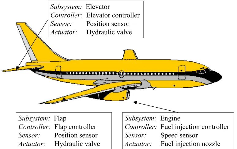
A. Complex control systems
A complex control system is a large-scale system containing several subsystems [3], which
control system is an altitude control system in an airplane [4] as shown in Fig. 2. In order to
maintain the altitude during an autopilot mode, three subsystems, which are the flaps, the
elevator, and the engine, must cooperate synchronously.
Subsystem: Elevator
Controller: Elevator controller
Sensor: Position sensor
Actuator: Hydraulic valve
Subsystem: Flap
Controller: Flap controller
Sensor: Position sensor
Actuator: Hydraulic valve
Subsystem: Engine
Controller: Fuel injection controller
Sensor: Speed sensor
Actuator: Fuel injection nozzle
Fig. 2. Altitude control system of airplane.
Because an actual complex control system is typically large and sophisticated, connecting
system components like sensors, actuators, and controllers together by direct electrical wiring
usually results in complicated circuits. The system as a whole could be difficult to install and
maintain. System connections can be even more cumbersome if system components are not
closely located physically. Networked control system configuration can be applied on a
complex control system to solve this problem by systematically organizing wiring connections
into a shared data network. Several practical complex control applications have successfully
utilized the networked control system concept for this purpose. These applications include
B. Remote control systems
Remote control systems have been used for two general reasons: convenience and safety. A
remote control system saves human operator place-to-place traveling time and protects the
operator from dangers in hazardous environments such as in the space and in a war zone. A
widely known example is the Mars rover as shown in Fig. 3.
Satellite
Remote site (Mars) Local site (Earth)
Control signal
Remote data Mars rover
Fig. 3. Remote control system of Mars rover.
In the past, a remote control system usually requires a specific connection link or media,
which may be limited to a point-to-point connection and have an expensive set-up cost. With
the evolving of communication technologies, an emerging alternative to expand remote
systems for more connections is to utilize wired or wireless data network resources by
configuring the system as networked control systems. Thus, the network media can be shared
among several remote control systems for expansions. In addition, the prices of network
devices for networks such as Ethernet have become affordable, while the performances are
rapidly improving. Therefore, the set-up cost for a remote control system can be much reduced
than before. Furthermore, with the widely-used Internet, the remote system could even be
controlled across continents without too much extra cost. Practical examples of networked
remote control systems are robot teleoperation [9] and distant learning laboratory [10, 11].
Because a networked control system transfers control and feedback data through a network,
system performance. The performance could be degraded and the system can even become
unstable. The network delay effect and impacts on system performance degradation and
instability are based on the characteristics of the networked control system. For example, for a
remote DC motor speed control, an oscillatory behavior may occur at the speed output if there
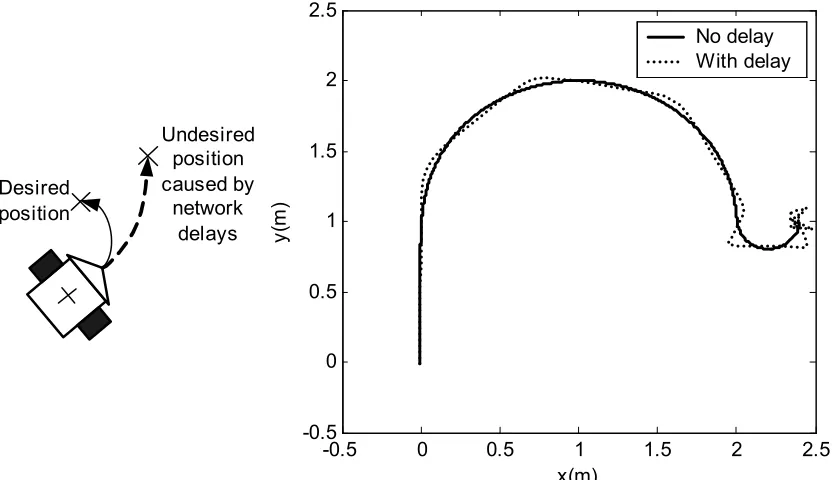
are network delays in the control loop. Likewise, on a remote networked mobile robot
path-tracking application, the robot may deviate from a desire position when it does not receive
timely control data from a controller across a network. Fig. 4 shows a typical comparison of
robot trajectories when the robot is controlled to track a path with and without network delays.
Desired position
Undesired position caused by
network delays
-0.5 0 0.5 1 1.5 2 2.5
-0.5 0 0.5 1 1.5 2 2.5
x(m)
y(
m
)
No delay With delay
Fig. 4. Comparison of robot tracks with and without network delay in the feedback control loop.
Apparently, the robot with network delays cannot track the desired path closely. To
maintain the networked control system performance as much as possible with the existence of
network delays, a networked control methodology is required to compensate the network delay
techniques and a novel networked control methodology using middleware gain adaptation will
be presented in later chapters of this dissertation.
II. Gain Scheduling
Gain scheduling is a special kind of nonlinear feedback control techniques. The concept of
gain scheduling originated from flight control applications [12-13], in which operating
conditions always change. In gain scheduling, controller parameters are functions of operating
conditions so called scheduling functions, which can usually be represented in a lookup table.
These operating conditions are usually parameterized into variables called auxiliary or
scheduling variables [13], that correlate with changes in the dynamics of the system. Choosing
appropriate auxiliary variables depends on the physics and characteristics of a system. In this
dissertation, data network traffic conditions will be characterized into network variables and
will be used as auxiliary variables. Fig. 5 shows the block diagram of a feedback control
system with gain scheduling.
Controller Plant
Scheduling function Controller
parameters
Operating condition
Reference
signal Control
signal Output
Fig. 5. Block diagram of feedback control system with gain scheduling.
When the operating condition of the control system changes, the controller parameters will
be adjusted with respect to the measurements of auxiliary variables. Nevertheless, there is no
typically not considered as an adaptive control technique. Because the parameters are updated
in an open-loop manner, parameter adaptation by gain scheduling could be viewed as a kind of
feedforward compensation. The performance and stability of the system with gain scheduling
are usually analyzed by extensive simulations. Analysis at the transition among operation
conditions is normally required more attention. Until now, gain scheduling has been applied on
various applications, and also in many cases along with other technologies such as robust
control, optimal control, and fuzzy control. Example of these applications are flight control
[14], arc welding [15], diesel engine [16], magnetic bearing [17], suspension system [18], and
DC motor [19].
III. Neural Networks
An artificial neural network (ANN) is a mathematical structure designed to model a brain
function of interests. In general, an ANN architecture is composed of processing elements
called neurons or nodes [20]. Fig. 6 shows the fundamental structure of a neuron.
Neuron
1
x w0
1
w
N w
1
x
N x
Input
∑
Activation function
f
o
b
p Output
The neuron receives the inputs x x1, , ,2 … xN, which are scaled by the weights w w1, 2, ,…
N
w , respectively. The summation of these inputs and the bias b is then applied as the input of
an activation function or atransfer function. This operation of a neuron can be described by:
( )
(
)
1
, n i i
i
o f p p w x b
=
= =
∑
+ (1)An activation function can be a linear or nonlinear function. However, popular choices of
activation functions are usually nonlinear functions, which are monotonically non-decreasing
and differentiable functions. Such activation functions include the sigmoid or logistic function,
and the hyperbolic tangent function.
One of the most widely-used ANN structures is the multilayer feedforward network with
one hidden layers illustrated in Fig. 7. Multilayer feedforward neural networks have been
successfully applied to solve several nonlinear and complicated problems such as fault
detection and diagnosis [21] and thermal modeling [22].
1 K k o1 ok oK w k1 w Kj w K1 wkj wKJ y1 yj
yJ=1
jthrow
of neurons
kthrow
of neurons w11 1 J j x1 xi
xN=1
ithrow
of neurons v j1 v11 vji v1i dummy neuron
vJI
Fig. 7. Multilayer feedforward neural network.
A prominent feature of an ANN is its ability to approximate a highly nonlinear mapping by
learning from a set of training data. This ability makes ANN very useful to approximate a
scheduling function from a collection of simulation or experimental data. A training data set is
composed of a set of input data and a set of the associated output data, which may be sampled
the training set, the ANN can represent the mapping between the inputs and outputs including
the points that were not acquired in the training set. This learning process of the ANN is called
supervised learning, which can be performed by a variety of training algorithms such as the
highly popular error-backpropagation algorithm [23].
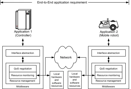
IV. Middleware
Middleware is an implementation to seamlessly manage connections among applications,
hardware and software resources such as CPU processing time and data network resources.
The interfaces of middleware to applications and resources are performed through abstract
levels, while actual hardware and software implementations and operations are hidden inside
the middleware. Applications developed from different platforms, languages, or procedures,
can communicate together or access resources using the same abstraction. This framework
provides modularity for application research and development, and ease to use and extend
Middleware Resource management
Controller
End-to-End application requirement
Remote system
Interface abstraction
Resource monitoring QoS negotiation
Network
Local hardware
and software
resources Middleware
Resource management Interface abstraction
Resource monitoring QoS negotiation
Application 1
(Controller) (Mobile robot)Application 2
Local hardware
and software resources
Fig. 8. A fundamental structure of middleware.
Middleware must have effective managing strategies for applications to access resources
through abstraction. In general, an application can access resources by negotiating with
middleware for its end-to-end application requirement. The requirement has to be mapped into
specifications so called QoS (Quality-of-Service) specifications, which indicate the quantity of
resource requirement such as required processing time, network bandwidth, delay bound, and
jitter. For example, if we would like a robot to track a path over a data network to reach a
destination in 15 s, the requirement can be mapped to the bandwidth and delay bound that the
robot needs in order to complete the task. Middleware then check if there are adequate
resources based on the resource monitoring measurements. If the requirement cannot be
granted, the application may need to lower its performance and performs as best as possible.
Middleware has been applied for control applications using various implementations such
as RTPOOL [24] and CORBA (Common Object Request Broker Architecture) [25]. The main
objective of middleware usages in these applications is to provide convenient interfaces and to
guarantee QoS. Especially, middleware can offer appropriate network conditions, for example,
bounds of delays and delay variations, for a networked control system. These applications
include flight control [24], robot control [26-28], and factory automation [29, 30].
V. Gain Scheduler Middleware (GSM)
In this dissertation, a novel methodology to adapt controller gain parameters by a gain
scheduling technique externally at the controller output through middleware is introduced. This
methodology is developed based on the requirement to enable existing controllers for
networked control purposes such that the controllers need not be redesigned or replaced by a
complete new networked control system. Otherwise, the installations of new network control
system are typically costly, inconvenient, and time consuming. The proposed methodology
could benefit major industries in factory automation and industrial electronics because a major
amount of existing controllers can be enabled or upgraded to be used over a data network.
Therefore, these industries can save much investment and time for controller upgrades. The
proposed methodology is defined as the gain scheduler middleware (GSM). The basic structure
of a GSM is shown in Fig. 9.
Controller
Gain scheduler middleware Network
traffic estimator Feedback
preprocessor
Gain scheduler
Network
Remote system Probing
Control signal
Feedback signal
A GSM is composed of three main parts: a network traffic estimator, a feedback
preprocessor, and a gain scheduler. The network estimator unit measures the current network
traffic conditions by periodically sending probing packets to a remote system in order to
characterize the network traffic conditions. The network traffic conditions and network
variables can be thought of as operating conditions and auxiliary variables in gain scheduling.
The feedback preprocessor unit preprocesses the feedback data such as filtering noise or
prediction of remote system states, and forwards the preprocessed data to an existing controller.
Note that the feedback preprocessor may not be necessary if the controller does not require
preprocessing. The controller then computes the updated control data. The gain scheduler then
captures the output of the controller, and modifies it by a gain scheduling algorithm with
respect to the network variables in order to compensate network delay effects. Illustrations of
GSM methodology applied on two applications: DC motor speed control system and mobile
robot path tracking will be described in this dissertation.
VI. Overview of the Dissertation
This dissertation contains several manuscripts that have been submitted for publication to
several journals. Chapter II of this dissertation is published in Control Engineering Practice,
Special Issue on Control Methods for Telecommunication Networks [31]. Chapter III is
published in IEEE Transactions on Industrial Electronics [32]. Chapter IV and V are the
companion papers that have been submitted to an IEEE Transactions and are currently under
review. Chapter VI is the paper to be submitted to another IEEE Transactions. There are also
several other conference papers have been published along the research investigated in this
dissertation [33-38].
Chapter II provides an introduction on networked control system technologies. General
information about networked control systems including system configuration, data transfers,
and network protocol characteristics for networked control systems are described. This chapter
techniques to compensate network delays. Suggestion of using these techniques on different
network protocol characteristics is also given.
Chapter III introduces the feasibility of using a gain scheduling technique to handle
network delays based on network traffic conditions. The network considered in this chapter is
assumed to be a QoS-enabled network, which can guarantee network traffic conditions for a
networked control system. A PI (Proportional-Integral) DC motor speed control problem is
used as an example to verify the feasibility and performance of the proposed gain scheduling
technique. A method to adapt controller gain parameters by gain scheduling is described.
Simulation and experimental results to show the effectiveness of the proposed approach are
also provided.
Chapter IV and V are companion chapters. In these chapters, the concept of using gain
scheduler middleware to adapt controller gains externally at the controller output with respect
to the current IP network traffic conditions is introduced. Chapter IV provides the fundamental
of network delay formulation in the frequency domain with the assumption that IP network
delays are constant. Control system formulation for gain scheduling, sensitivity analysis, and
optimal gain parameter finding are also described. Chapter V describes the generalization of
the approach in chapter IV for actual IP network delays. The characteristics of actual IP
network delays and characterization of IP network delays by a generalized exponential
distribution are analyzed in this chapter. Optimal gain finding based on the generalized
exponential distribution is then explained. The gain scheduler middleware concept for
networked control is then described. Performance verification of the proposed approach on a PI
DC motor speed control problem in simulations is also described in this chapter.
Chapter VI presents the use of gain scheduler middleware on a mobile robot application
controlled with the existence of IP network delays. An example to illustrate the effectiveness of
middleware in this chapter is a mobile robot path-tracking problem. Likewise, the gain
respect to the current network traffic conditions. However, the structure of gain scheduler
middleware is slightly different from chapter IV and V. The gain scheduler middleware in this
chapter preprocesses the feedback data before forwarding preprocessed data to the robot
path-tracking controller. Simulation and experimental results to verify the effectiveness of the gain
scheduler middleware are described and presented at the end of this chapter.
References
[1] G. C. Walsh, H. Ye, and L. Bushnell, "Stability analysis of networked control systems,"
in American Control Conference, San Diego, CA, 1999, pp. 2876-2880.
[2] Y. H. Kim, H. S. Park, and W. H. Kwon, "Stability and a scheduling method for
network-based control systems," in IEEE IECON 96, Taipei, Taiwan, 1996, pp. 934-939.
[3] H. Chan and Ü. Özgüner, "Closed-loop control of systems over a communication
network with queues," International Journal of Control, vol. 62, no. 3, pp. 493-510,
1995.
[4] B. Etkin and L. D. Reid, Dynamics of Flight: Stability and Control. New York: Wiley,
1996.
[5] Ü. Özgüner, H. Göktas, H. Chan, J. Winkelman, M. Liubakka, and R. Krotolica,
"Automotive suspension control through a computer communication network," in IEEE Control Applications, Dayton, OH, 1992, pp. 895-900.
[6] N. Boustany, M. Folkerts, K. Rao, A. Ray, L. Troxel, and Z. Zhang, "A simulation
based methodology for analyzing network-based intelligent vehicle control systems," in Intelligent Vehicles Symposium, 1992, pp. 138-143.
[7] B. P. Zeigler and J. Kim, "Extending the DEVS-Scheme knowledge-based simulation
environment for real-time event-based control," IEEE Transactions on Robotics and
Automation, vol. 9, no. 3, pp. 351-356, 1993.
[8] G. Kaplan, "Ethernet's winning ways," IEEE Spectrum, vol. 38, no. 1, pp. 113-115,
2001.
[9] K. Brady and T.-J. Tarn, "Internet-based teleoperation," in IEEE ICRA 2001, Seoul,
South Korea, 2001, pp. 644-649.
[10] J. W. Overstreet and A. Tzes, "An Internet-based real-time control engineering
[11] G. V. Kondraske, R. A. Volz, D. H. Johnson, D. Tesar, J. C. Trinkle, and C. R. Price, "Network-based infrastructure for distributed remote operations and robotics research,"
IEEE Transactions on Robotics and Automation, vol. 9, no. 5, pp. 702-704, 1993.
[12] G. Stein, "Adaptive flight control-A pragmatic view," in Applications of Adaptive
Control, K. S. Narendra and R. V. Monopoli, Eds. New York: Academic Press, 1980, pp. 291-312.
[13] K. J. Åström and B. Wittenmark, Adaptive Control. Reading, MA: Addison-Wesley,
1989.
[14] R. A. Nichols, R. T. Reichert, and W. J. Rugh, "Gain scheduling for H-infinity
controllers: a flight control example," IEEE Transactions on Control Systems
Technology, vol. 1, no. 2, pp. 69-79, 1993.
[15] J. B. Bjorgvinsson, G. E. Cook, and K. Andersen, "Microprocessor-based arc voltage
control for gas tungsten arc welding using gain scheduling," IEEE Transactions on
Industry Applications, vol. 29, no. 2, pp. 250-255, 1993.
[16] J. Jiang, "Optimal gain scheduling controller for a diesel engine," IEEE Control
Systems Magazine, vol. 14, no. 4, pp. 42-48, 1994.
[17] F. Matsumura, T. Namerikawa, K. Hagiwara, and M. Fujita, "Application of gain
scheduled H∞ robust controllers to a magnetic bearing," IEEE Transactions on Control
Systems Technology, vol. 4, no. 5, pp. 484-493, 1996.
[18] S.-H. Lee, S.-G. Kim, and J.-T. Lim, "Fuzzy-logic-based fast gain-scheduling control
for nonlinear suspension systems," IEEE Transactions on Industrial Electronics, vol.
45, no. 6, pp. 953-955, 1998.
[19] M. R. Matausek, B. I. Jeftenic, D. M. Miljkovic, and M. Z. Bebic, "Gain scheduling
control of DC motor drive with field weakening," IEEE Transactions on Industrial
Electronics, vol. 43, no. 1, pp. 153-162, 1996.
[20] M.-Y. Chow and J. Teeter, Methodologies of Using Artificial Neural Network and
Fuzzy Logic Technologies for Motor Incipient Fault Detection, 1 ed. Farrer Road, Singapore: World Scientific, 1997.
[21] B. Li, M.-Y. Chow, Y. Tipsuwan, and J. C. Hung, "Neural-network-based motor rolling
bearing fault diagnosis," IEEE Transactions on Industrial Electronics, vol. 47, no. 5,
pp. 1060-1069, 2000.
[23] D. E. Rumelhart and J. L. McClelland, Parallel Distributed Processing: Explorations in the Microstructure of Cognition. Cambridge, MA: MIT Press, 1986.
[24] T. F. Abdelzaher, E. M. Atkins, and K. G. Shin, "QoS negotiation in real-time systems
and its application to automated flight control," IEEE Transactions on Computers, vol.
49, no. 11, pp. 1170-1183, 2000.
[25] D. G. Schmidt and F. Kuhns, "An overview of the Real-Time CORBA specification,"
Computer, vol. 33, no. 6, pp. 56-63, 2000.
[26] D. Brugali and M. E. Fayad, "Distributed computing in robotics and automation," IEEE
Transactions on Robotics and Automation, vol. 18, no. 4, pp. 409-420, 2002.
[27] O. Kubitz, M. O. Berger, and R. Stenzel, "Client-server-based mobile robot control,"
IEEE/ASME Transactions on Mechatronics, vol. 3, no. 2, pp. 82-90, 1998.
[28] H. Utz, S. Sablatnog, S. Enderle, and G. Kraetzschmar, "Miro-middleware for mobile
robot applications," IEEE Transactions on Robotics and Automation, vol. 18, no. 4, pp.
493-497, 2002.
[29] Z. Yang, G. Huang, R. L. Y. Guan, and R. Gay, "CORBA as object-oriented infrastructure for factory communication and control," in APCC/OECC 1999, Beijing, China, 1999, pp. 1083-1086.
[30] S. Song, J. Huang, P. Kappler, R. Freimark, and T. Kozlik, "Fault-tolerant Ethernet middleware for IP-based process control networks," in IEEE Local Computer Networks, Tampa, FL, 2000, pp. 116-125.
[31] Y. Tipsuwan and M.-Y. Chow, "Control methodologies in networked control Systems,"
to be published in Control Engineering Practice, vol. 10, no. 11, pp. 1099-1111, 2003.
[32] M.-Y. Chow and Y. Tipsuwan, "Gain adaptation of networked DC motor controllers
based on QoS variations," to be published in IEEE Transactions on Industrial
Electronics, vol. 50, no. 5, 2003.
[33] M.-Y. Chow and Y. Tipsuwan, "Network-based control adaptation for network QoS variation," in IEEE MILCOM 2001, Vienna, VA, 2001, pp. 257-261
[34] N. B. Almutairi, M.-Y. Chow, and Y. Tipsuwan, "Network-based controlled DC motor with fuzzy compensation," in IEEE IECON 2001, Denver, CO, 2001, pp. 1844-1849.
[36] Y. Tipsuwan and M.-Y. Chow, "Gain adaptation of networked mobile robot to compensate QoS deterioration," in IEEE IECON 2002, Sevilla, Spain, 2002, pp. 3146-3151.
[37] Y. Tipsuwan and M.-Y. Chow, "On the gain scheduling for networked PI controller over IP Network," in IEEE/ASME AIM, Kobe, Japan, 2003, pp. 640-645.
17
C H A P T E R I I
CONTROL METHODOLOGIES IN NETWORKED CONTROL
SYSTEMS
This chapter is published in Control Engineering Practice, Special Issue on Control Methods
for Telecommunication Networks, vol. 10, no. 11, pp. 1099-1111. Yodyium Tipsuwan Mo-Yuen Chow
[email protected] [email protected]
Advanced Diagnosis And Control Lab Department of Electrical and Computer Engineering North Carolina State University, Raleigh NC 27606, USA
CONTROL METHODOLOGIES IN NETWORKED CONTROL
SYSTEMS
Abstract—The use of a data network in a control loop has gained increasing attentions in
recent years due to its cost effective and flexible applications. One of the major challenges in
this so called networked control system (NCS) is the network-induced delay effect in the
control loop. Network delays degrade the NCS control performance and destabilize the system.
A significant emphasis has been on developing control methodologies to handle the network
delay effects in NCS. This survey paper presents recent NCS control methodologies. The
overview on NCS structures and description of network delays including characteristics and
effects are also covered.
Keywords—communication control applications, communication networks, communication protocols, distributed control, factory automation, delay analysis, delay compensation.
I. Introduction
The research and developments on shared data networks have a long history. Principle data
networks such as Slotted ALOHA [1], and ARPANET [2], which were specially developed
around 30-40 years ago, evolved to widely used modern network protocols like Ethernet and
Internet for general usages, respectively. Data networking technologies provide several benefits
on linking data points like computers. Networks enable remote data transfers and data
exchanges among users, reduce the complexity in wiring connections and the costs of medias,
and provide ease in maintenance.
Because of these attractive benefits, many industrial companies and institutes have shown
interest in applying networks for remote industrial control purposes and factory automation. As
have been released. For example, CAN (Controller Area Network) was originally developed in
1983 by the German company Robert Bosch for use in car industries, and is also being used
now in many other industrial control applications. Another example of industrial networks is
Profibus developed by six German companies and five German institutes in 1987. Profibus is a
broadcast bus protocol that operates as a multi-master/slave system. Many other industrial
network protocols including Foundation Fieldbus and DeviceNet were also developed about
the same time period. Most of these protocols are typically reliable and robust for real-time
control purposes.
Meanwhile, the technologies on general computer networks especially Ethernet have also
progressed very rapidly. With the decreasing price, increasing speed, widespread usages,
numerous software and applications, and well-established infrastructure, these networks
become major competitors to the industrial networks for control applications [3]. Furthermore,
the popularity of the Internet has brought these networks into various organizations. Thus, the
control applications can utilize these networks to connect to the Internet in order to perform
remote control at much farther distances than in the past without investing on the whole
infrastructure. Although the industrial networks have been enhanced for Internet connectivity,
the cheaper price and widespread usages of the general networks are still attractive for use in
control applications.
Regardless of the type of network used, the overall networked control system performance
is always affected by network delays since the network is tied with the control system. Delays
are widely known to degrade the performance of a control system. Network delays may not
significantly affect an open-loop control system such as on-off relay systems in industrial
plants. However, the open-loop control configuration may not be appropriate and adequate for
time-sensitive high performance control applications such as telerobotics and telesurgery.
These applications require feedback data sent across the network in order to correct the output
controlling a system over the network since network delays are usually time-varying,
especially in the Internet. Therefore, to handle network delays in a closed-loop control system
over a network, an advanced methodology is required.
This survey paper provides recent control methodologies for a closed-loop control system
over a data network. This closed-loop system configuration is known as a network-based
control system [4] or networked control system (NCS) [5]. The two terms are somewhat interchangeable depending on different authors’ preferences. The methodologies described in
this paper have been applied and have shown promising results in many applications ranging
from DC motors [6, 7] to automobiles [8, 9], aircrafts [10], mobile robots [11, 12], robotic
manipulator [13], and distance learning [14, 15]. This paper provides the overview of NCS
including system configuration, network delay characteristics, and the effects of networked
delays in section II. The control methodologies for NCS will then be described in section III.
The paper is concluded in section IV.
II. Overview of Networked Control System
A. Networked control system configuration
There are two general networked control system configurations listed as follows:
Direct structure
The NCS in the direct structure is composed of a controller and a remote system containing
a physical plant, sensors and actuators. The controller and the plant are physically located at
different locations and are directly linked by a data network in order to perform remote
Network Control signal
Sensor measurement
Controller Plant
Actuator
Sensor , : Packet
Fig. 1. NCS in the direct structure.
The control signal is encapsulated in a frame or a packet and sent to the plant via the
network. The plant then returns the system output to the controller by putting the sensor
measurement into a frame or a packet as well. In a practical implementation, multiple
controllers can be implemented in a single hardware unit to manage multiple NCS loops in the
direct structure. Some examples of NCS in the direct structure are a distance learning lab [15]
and a DC motor speed control system [6].
Hierarchical structure
The basic hierarchical structure consists of a main controller and a remote closed-loop
system as depicted in Fig. 2.
, : Packet
Remote system Network
Reference signal
Sensor measurement Main
controller
Plant
Actuator Sensor
Remote controller
-+
Fig. 2. NCS in the hierarchical structure.
Periodically, the main controller computes and sends the reference signal in a frame or a
packet via a network to the remote system. The remote system then processes the reference
signal to perform local closed- loop control and returns to the sensor measurement to the main
controller for networked closed-loop control. The networked control loop usually has a longer
sampling period than the local control loop since the remote controller supposes to satisfy the
structure, the main controller can be implemented to handle multiple networked control loops
for several remote systems. This structure is widely used in several applications including
mobile robots [12], and teleoperation [13].
The use of either the direct structure or the hierarchical structure is based on application
requirements and designer’s preferences. For example, a robotic manipulator usually requires
several motors at the joints of the robot to simultaneously and smoothly rotate together. It may
be more convenient and more robust to use an existing robot controller and formulate the
networked control problem in the hierarchical structure. On the other hand, a designer may
require a networked DC motor speed control system [6] to have a faster control response over
the network. The direct structure may be preferred in this case.
This survey paper mainly focuses on the fundamental and control methodologies for NCS
in the direct structure. Nevertheless, control and analysis methodologies for the direct structure
could also be applied for the hierarchical structure by treating the remote closed-loop system as
a pure plant. In this case, the remote closed-loop system is represented by a state-space model
or a transfer function similar to the plant.
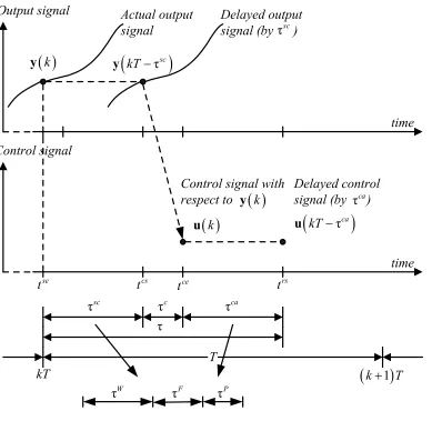
B. Delays in-the-loop
Since an NCS operates over a network, data transfers between the controller and the remote
system will induce network delays in addition to the controller processing delay. Fig. 3 shows
network delays in the control loop, where r is the reference signal, u is the control signal, y is
the output signal, k is the time index, and T is the sampling period. Most of networked control
methodologies use the discrete-time formulation shown in Fig. 3. Fig. 4 shows the
Remote system
( )k ( )kT u u
Actuator y( )t
( )k ( )kT
y y T
(
kT−τsc)
y
( ) ( )k kT
r r u
(
kT−τca)
Z.O.H Controller
Network
Plant Sensor
Fig. 3. General NCS configuration and network delays for NCS formulations.
T
τsc τc τca
τ
kT
Control signal
( )
ku u
(
kT−τca)
se
t tcs trs
Output signal
( )
ky y
(
kT−τsc)
(
k+1)
T τscActual output signal
Delayed output signal (by )
Control signal with respect to y
( )
kDelayed control signal (by )τca
time
time ce
t
τW τF τP
Network delays in an NCS can be categorized from the direction of data transfers as the
sensor-to-controller delay τsc and the controller-to-actuator delay τca. The delays are
computed as:
τsc =tcs−tse, (1)
τca =trs−tce, (2)
where tse is the time instant that the remote system encapsulates the measurement to a frame or
a packet to be sent, tcs is the time instant that the controller starts processing the measurement
in the delivered frame or packet, tce is the time instant that the main controller encapsulates the
control signal to a packet to be sent, and trs is the time instant that the remote system starts
processing the control signal. In fact, both network delays can be longer or shorter than the
sampling time T. The controller processing delay τc and both network delays can be lumped
together as the control delay τ for ease of analysis. This approach has been used in some
networked control methodologies. Although the controller processing delay τc always exists,
this delay is usually small compared to the network delays, and could be neglected. In addition,
the sampling periods of the main controller and of the remote system may be different in some
cases.
The delays τsc and τca are composed of at least the following parts [16].
Waiting time delay τW
The waiting time delay is the delay, of which a source (the main controller or the remote
system) has to wait for queuing and network availability before actually sending a frame or a
packet out.
Frame time delay τF
The frame time delay is the delay during the moment that the source is placing a frame or a
Propagation delay τP
The propagation delay is the delay for a frame or a packet traveling through a physical
media. The propagation delay depends on the speed of signal transmission and the distance
between the source and destination.
These three delay parts are fundamental delays that occur on a local area network. When
the control or sensory data travel across networks, there can be additional delays such as the
queuing delay at a switch or a router, and the propagation delay between network hops. The
delays τsc and τca also depend on other factors such as maximal bandwidths from protocol
specifications, and frame or packet sizes.
Higher layer network protocols such as TCP may require retransmission if an error occurs
in a packet, or a switch or a router drops the packet. This incident is a trade-off for an NCS.
Even though some control or sensory signals are lost due to network transmissions, some NCS
may operate acceptably. In this case, retransmission may be undesirable because the NCS may
be severely affected by the extending delays as a result from retransmission.
C. Delay characteristics
The delay characteristics on NCS basically depend on the type of a network used, which
are described as follows.
Cyclic service network
In local area network protocols with cyclic service such as IEEE 802.4, SAE token bus,
PROFIBUS, IEEE 802.5, SAE token ring, MIL-STD-1553B, and FIP, control and sensory
signals are transmitted in a cyclic order with deterministic behaviors. Thus, the delays are
periodic and can be simply modeled as a periodic function such that τsc τsc1
k = k+ and τcak =τcak+1,
where τsc
k and τ
ca
k are the sensor-to-controller delay and the controller-to-actuator delay at the
sampling time period k [17]. The models work perfectly in the ideal case. In practice, NCS may
discrepancies in clock generators on a controller and a remote system may result in delay
variations.
Random access network
Random access local area networks such as CAN and Ethernet involve with more uncertain
delays. The significant parts of random network delays are the waiting time delays due to
queuing and frame collision on the networks. When an NCS operates across networks, several
more factors can increase the randomness on network delays such as the queuing time delays at
a switch or a router, and the propagation time delays from different network paths. In addition,
a cyclic service network connected to a random access network also results in random delays.
In the networking area, random network delays have been modeled by using various
formulations based on probability and the characteristics of sources and destinations. The
techniques range from simple approaches such as the Poisson process to more sophisticated
approaches such as Markov chain [18], fluid flow model [19], ARMA model [20], etc. These
techniques have been brought to NCS formulations in several studies, but may have to be
modified or reformulated for specific networked control methodologies. For example, Markov
chain is applied in [21, 22], and simple independent transfer-to-transferprobability distribution
models are used in [22] as follows.
( ) (
τca δ τca)
(
1)
δ τ(
ca)
k k ca k ca
fτ = − ⋅ −a p + − ⋅b p , (3)
( )
(
)
(
)
(
)
(
]
[ ]
δ τ 1 , τ ,
τ , τ , , ,
0, τ , ,
sc sc
k sc k
sc sc
k sc k
sc k
a p a
f p b a a b a b
a b +
− ⋅ − =
= − ∈ <
∉
τ (4)
where δ
( )
⋅ is the Dirac delta function, a and b are constants, and p psc, ca∈[ ]
0,1 areD. Effects of delays in-the-loop
Performance degradation
Delays in a control loop are widely known to degrade system performances of a control
system, so are the network delays in an NCS. The closed-loop PI (Proportional-Integral)
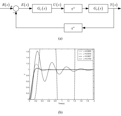
control system with delays in Fig. 5 (a) is used to briefly illustrate system performance
degradations by delays in-the-loop, where R s
( )
, U s( )
, Y s( )
, and E s( )
=R s( ) ( )
−Y s arethe reference, control, output, and error signals in Laplace domain according to the reference,
control, output, and error signals in time domain, respectively.
The transfer functions of the controller and the plant are described, respectively, as follows:
( )
, 0.1701, 0.378I P
P
C P I
K
K s
K
G s K K
s
β +
= = = , (5)
( ) (
26.292029.826)(
2.296)
P
G s
s s
=
+ + , (6)
where G sC
( )
is a PI controller, KP is the proportional gain, KI is the integral gain, G sP( )
isthe plant of a DC motor in [23], β is a parameter to adjust KP and KI. In this case, β =1. As
shown in Fig. 5 (b), obvious system performance degradations are the higher overshoot and the
longer settling time when the delays τca =τsc =τ/ 2 are longer. Other kinds of performance
degradations can be evaluated based on different performance measures. Analyses on the
effects of delays on system performance measures can be used for developing appropriate
τca
( )
C G s
( )
R s
( )
P
G s Y s
( )
τsc
( )
U s
( )
E s
(a)
0 0.2 0.4 0.6 0.8 1 1.2 1.4 1.6 1.8 2 0
0.2 0.4 0.6 0.8 1 1.2 1.4 1.6
Time(s)
y
τ=0.0005
τ=0.0232
τ=0.0627
τ=0.3150
(b)
Fig. 5. System performance degradations caused by delays in-the-loop: (a) Closed-loop
control system example. (b) Step response with respect to various τ, where τca =τsc =τ/ 2
are constant, and β =1.
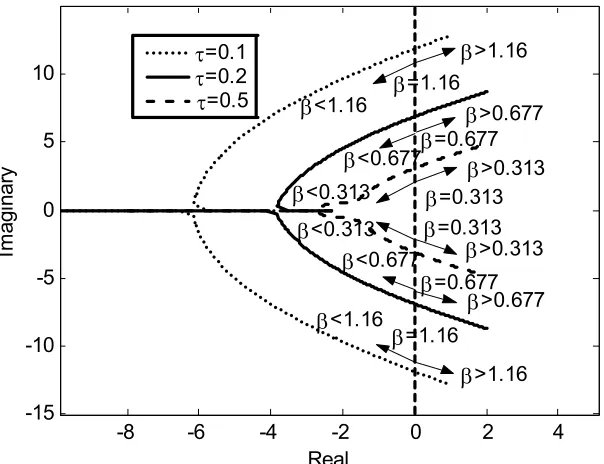
Destabilization
Delays in-the-loop including network delays in an NCS can destabilize the system by
reducing the system stability margin. Again, the system in Fig. 5 (a) is used to illustrate how
the delays can reduce the stability region. Fig. 6 shows the branches of the root locus of the
system in Fig. 5 (a) with respect to the parameter β . In this case, increasing β is equivalent to
primary branches are shown because they are sufficient to approximate the stability region
[25].
-8 -6 -4 -2 0 2 4
-15 -10 -5 0 5 10
Real
Im
agi
nar
y
β>1.16
β<1.16 β>0.677
β>0.313
β>0.313
β<0.677
β<0.313
β<0.313
β<0.677
β=1.16
β>1.16
β<1.16
β=1.16
β>0.677
β=0.677
β=0.677
β=0.313
τ=0.1
τ=0.2
τ=0.5
β=0.313
Fig. 6. Primary branches of the root locus of the system in Fig. 5 (a) with respect to β ,
where τca =τsc=τ/ 2 are constant.
As shown in Fig. 6, when the delay τ is longer, the primary branches of the root locus
bend toward the right of the imaginary axis, and β , at the point at which the branches cross
the imaginary axis, is smaller. This result indicates the narrower stability region since the PI
controller has the smaller range of feasible values to use for a stable closed-loop control.
There have been several studies to derive stability criteria for an NCS in order to guarantee
that the NCS can remain stable in a certain condition. However, there is no generic stability
analysis that can be applied on every NCS. Most of stability analysis techniques are subject to
network configurations, network protocols, assumptions, and control techniques used.
Simple stability analysis for a discrete-time delayed system in [26] can be applied to a
various system formulations. For example, an NCS on a periodic delay network in [17] is
stable if all eigenvalues of a specific formulation are contained in a unit circle. Another
formulation in [27] uses a general frequency domain analysis for checking stability, but the
stability criterion is limited to a single-dimensional system.
Stability analysis for an NCS with random network delays is more challenging, since more
advanced algorithms are usually required. Varieties of techniques have been used for different
NCS formulations. For example, in [22] and [21], stabilities of NCS were analyzed based on
stochastic stability analysis, but with different formulations. Nonlinear control and perturbation
theories were applied for NCS stability analysis in [5] using Bellman-Gronwall Lemma. A
hybrid system technique is used to analyze the stability of an NCS in [28].
III. Recent Networked Control Methodologies
Due to network delay concerns, the methodologies to control an NCS have to maintain the
stability of the system in addition to controlling and maintaining the system performance as
much as possible. Various methodologies have been formulated based on several types of
network behaviors and configurations in conjunction with different ways to treat the delay
problems. Some assumptions may be required. For example:
Network transmissions are error-free.
Every frame or packet always has the same constant length.
The difference between the sampling times of the controller and of the sensor, called
time skew ∆k, is constant.
The computational delay τc is constant and is much smaller than the sampling period
T.
The network traffic cannot be overloaded.
Every dimension of the output measurement or the control signal can be packed into