University of Windsor University of Windsor
Scholarship at UWindsor
Scholarship at UWindsor
Electronic Theses and Dissertations Theses, Dissertations, and Major Papers
2009
Biotextured Nanocrystalline Materials with Superhydrophobic
Biotextured Nanocrystalline Materials with Superhydrophobic
Surfaces and Controlled Friction and Wear
Surfaces and Controlled Friction and Wear
Mehdi Shafiei
University of Windsor
Follow this and additional works at: https://scholar.uwindsor.ca/etd
Recommended Citation Recommended Citation
Shafiei, Mehdi, "Biotextured Nanocrystalline Materials with Superhydrophobic Surfaces and Controlled Friction and Wear" (2009). Electronic Theses and Dissertations. 465.
BIOTEXTURED NANOCRYSTALLINE
MATERIALS WITH
SUPERHYDROPHOBIC SURFACES AND
CONTROLLED FRICTION AND WEAR
by
Mehdi Shafiei
A Dissertation
Submitted to the Faculty of Graduate Studies
through Engineering Materials
in Partial Fulfillment of the Requirements for
the Degree of Doctor of Philosophy at the
University of Windsor
Windsor, Ontario, Canada
2009
APPROVED BY:
Dr. G. Botton, External Examiner McMaster University
Dr. S.H. Eichhorn
Department of Chemistry & Biochemistry
Dr. D.O. Northwood
Department of Mechanical, Automotive & Materials Engineering
Dr. A. Edrisy
Department of Mechanical, Automotive & Materials Engineering
Dr. A.T. Alpas, Advisor
Department of Mechanical, Automotive & Materials Engineering
Dr. B. Budkowska, Chair of Defense
DECLARATION OF CO-AUTHORSHIP/
PREVIOUS PUBLICATION
I. Co-Authorship Declaration
I hereby declare that this thesis does not incorporate material that is result of joint research. In all cases, the key ideas, primary contributions, experimental designs, data analysis and interpretation, were performed by the author and Dr. A.T. Alpas as advisor.
I certify that, with the above qualification, this thesis, and the research to which it refers, is the product of my own work.
II. Declaration of Previous Publication
This thesis includes 6 original papers that have been previously published/ submitted for publication in peer reviewed journals/conference proceedings, as follows:
Thesis
Chapter Publication title/full citation
Publication status
Chapter 2
M. Shafiei and A.T. Alpas, Friction and Wear Mechanisms of Nanocrystalline Nickel in Ambient and Inert
Atmospheres, Metallurgical and Materials Transactions A38 (2007) 1621-1631.
Published
Chapter 3 M. Shafiei and A.T. Alpas, Effect of Sliding Speed on Friction and Wear Behaviour of Nanocrystalline Nickel Tested in an Argon Atmosphere, Wear 265 (2008) 429-438.
Published
Chapter 4 M. Shafiei and A.T. Alpas, High-Temperature Friction and Wear Mechanisms of Nanocrystalline Nickel Composite Coatings, Surface & Coatings Technology.
To be submitted
Chapter 5
M. Shafiei and A.T. Alpas, Friction and Wear Behaviour of Nanocrystalline Cobalt, Proceedings of the STLE/ ASME International Joint Tribology Conference, San Diego, CA, USA, October 2007, Paper # 44131.
Published
Chapter 6
M. Shafiei and A.T. Alpas, Fabrication of Biotextured Nanocrystalline Nickel Films for the Reduction and Control of Friction, Materials Science and Engineering C28 (2008) 1340-1346.
Published
Chapter 7
M. Shafiei and A.T. Alpas, Nanocrystalline Nickel Films
I certify that I have obtained a written permission from the copyright owner(s) to include the above published material(s) in my thesis. I certify that the above material describes work completed during my registration as graduate student at the University of Windsor.
I declare that, to the best of my knowledge, my thesis does not infringe upon anyone’s copyright nor violate any proprietary rights and that any ideas, techniques, quotations, or any other material from the work of other people included in my thesis, published or otherwise, are fully acknowledged in accordance with the standard referencing practices. Furthermore, to the extent that I have included copyrighted material that surpasses the bounds of fair dealing within the meaning of the Canada Copyright Act, I certify that I have obtained a written permission from the copyright owner(s) to include such material(s) in my thesis.
ABSTRACT
This study aimed to develop new wear-resistant materials with superhydrophobic
surfaces and low friction by combining the high strength of nanocrystalline (NC)
materials with the biological surface textures. This goal was accomplished in three stages.
First, the tribological properties of electrodeposited NC Ni and NC Co were studied,
and the role of the oxide-rich tribolayers in reducing the friction and wear rates was
delineated. For the NC Ni, micromechanisms of wear in different testing environments
were characterized, and the sliding-speed sensitivity of friction and wear rate was
investigated. A modified Archard equation was proposed to predict the wear rates of NC
Ni as a function of grain size and sliding speed. Additionally, it was found that the
high-temperature wear resistance of NC Ni could be improved by using SiC nanoparticles as
reinforcements.
In the second stage, NC Ni replicas of the surface textures of a lotus leaf and a snake
skin were fabricated through replication and electrodeposition. The NC Ni snake skin
replica displayed anisotropic frictional properties, due to the asymmetric shape of the
protrusions at the scales’ ridges. The NC Ni lotus leaf replica featured a high density of
microscale conical protuberances that prompted a 30% lower peak coefficient of friction
(COF) compared to a smooth surface, due to a smaller real area of contact.
In the third stage, the surface texture of the NC Ni lotus leaf replica was modified
using a short-duration electrodeposition process that increased the radius of the
protuberance tips, followed by a perfluoropolyether (PFPE) solution treatment that
reduced the surface energy and resulted in a multi-level surface roughness consisting of a
surfaces had a high water contact angle of 156°, similar to that of the natural lotus leaf,
DEDICATION
I would like to dedicate this dissertation to my parents for their unconditional love,
ACKNOWLEDGMENTS
This study could not have gone forward without the financial support from the
Natural Sciences and Engineering Research Council of Canada (NSERC).
I would like to thank my doctoral advisor, Dr. A.T. Alpas, for his dedication to
high-quality research and his continuous support during the course of this study.
I would like to thank my committee members (Dr. G. Botton, Dr. A. Edrisy, Dr. S.H.
Eichhorn and Dr. D.O. Northwood) for their helpful comments and careful review of this
work. In particular, I am grateful to Dr. G. Botton for providing access to the Canadian
Centre for Electron Microscopy.
I would like to thank Dr. Y.T. Cheng from the University of Kentucky, Dr. G. de
Silveira from the McMaster University, Dr. X. Meng-Burany from the University of
Windsor and Dr. S.M. Tadayyon from the University of Western Ontario for useful
discussions.
I would like to thank Mr. A. AbouGharam, Dr. S. Akarca, Ms. N. Dalili, Dr. M.
Elmadagli, Ms. S. Lackie, Mr. J. Robinson, Ms. C. Smeaton and Mr. P. Zhang from the
University of Windsor for their assistance with the experiments.
I would like to thank Ms. J. de Vries for her help and encouragement.
Finally, I am thankful to the faculty, staff and graduate students at the Department of
Mechanical, Automotive and Materials Engineering of the University of Windsor,
TABLE OF CONTENTS
DECLARATION OF CO-AUTHORSHIP/ PREVIOUS PUBLICATION iii
ABSTRACT v DEDICATION vii ACKNOWLEDGMENTS viii
LIST OF TABLES xiii
LIST OF FIGURES xiv
LIST OF ABBREVIATIONS xxii
NOMENCLATURE xxiv
I. CHAPTER 1: INTRODUCTION 1
1. GENERAL OVERVIEW 1
2. NANOCRYSTALLINE MATERIALS 6
2.1. Production of Nanocrystalline Materials 6
2.2. Microstructures of Nanocrystalline Materials 8
2.3 Properties of Nanocrystalline Materials Influencing Tribological
Behaviour 11 3. TRIBOLOGICAL PROPERTIES OF BIOLOGICAL SYSTEMS RESULTING
FROM SURFACE TEXTURE 16
3.1. Low-Friction Surfaces 16
3.2. High-Friction Surfaces 17
3.3. Surfaces with Anisotropic Frictional Properties 18
3.4. Superhydrophobic Surfaces 19
REFERENCES 21 FIGURES 25
II. CHAPTER 2: FRICTION AND WEAR MECHANISMS OF NANOCRYSTALLINE NICKEL IN AMBIENT AND INERT
ATMOSPHERES 40
1. INTRODUCTION 40
2. EXPERIMENTAL PROCEDURES 42
3.2. Wear Tracks Developed during Initial and Steady-State Stages of Wear
under Ambient Atmospheric Conditions 46
3.3. Friction and Wear Rates under an Argon Atmosphere 48
3.4. Wear Tracks Developed during Initial and Steady-State Stages of Wear
under Argon Atmosphere 50
4. SUMMARY AND CONCLUSIONS 52
REFERENCES 55
TABLE 57 FIGURES 58
III. CHAPTER 3: EFFECT OF SLIDING SPEED ON FRICTION AND WEAR BEHAVIOUR OF NANOCRYSTALLINE NICKEL IN AN ARGON
ATMOSPHERE 69
1. INTRODUCTION 69
2. EXPERIMENTAL PROCEDURES 71
2.1. Microstructure 71
2.2. Mechanical Property Measurements 73
2.3. Friction and Wear Tests 73
3. RESULTS 74
3.1. Mechanical Properties 74
3.2. Friction and Wear Behaviour 76
4. DISCUSSION 79
4.1. Wear Mechanisms of Nanocrystalline Nickel in Comparison with
Microcrystalline Nickel 79
4.2. A Phenomenological Analysis of Wear Rate-Sliding Speed Relationship 81 4.3. Micromechanisms Responsible for Sliding-Speed Sensitivity in
IV. CHAPTER 4: HIGH-TEMPERATURE FRICTION AND WEAR MECHANISMS OF NANOCRYSTALLINE NICKEL COMPOSITE
COATINGS 98
1. INTRODUCTION 98
2. EXPERIMENTAL PROCEDURES 99
3. RESULTS AND DISCUSSION 102
3.1. Contact Surface Morphologies, Wear Rates and Coefficients of Friction 102
3.2. Microstructural Evolution during Sliding Wear 104
4. CONCLUSIONS 106
REFERENCES 107 FIGURES 108
V. CHAPTER 5: FRICTION AND WEAR BEHAVIOUR OF
NANOCRYSTALLINE COBALT 120
1. INTRODUCTION 120
2. EXPERIMENTAL PROCEDURES 121
3. RESULTS AND DISCUSSION 121
3.1. Friction, Volume Loss and Wear Rate 121
3.2. Wear Mechanisms 122
4. CONCLUSIONS 123
REFERENCES 124 FIGURES 125
VI. CHAPTER 6: FABRICATION OF BIOTEXTURED NANOCRYSTALLINE NICKEL FILMS FOR THE REDUCTION AND CONTROL OF FRICTION 130
1. INTRODUCTION 130
2. EXPERIMENTAL PROCEDURES 131
3. RESULTS AND DISCUSSION 132
3.1. Nanocrystalline Nickel Replica of Lotus Leaf: Reducing Friction 132 3.2. Nanocrystalline Nickel Replica of the Boa’s Skin: Obtaining Anisotropic
Frictional Properties 136
TABLE 140 FIGURES 141
VII. CHAPTER 7: NANOCRYSTALLINE NICKEL FILMS WITH LOTUS LEAF TEXTURE FOR SUPERHYDROPHOBIC AND LOW FRICTION
SURFACES 148
1. INTRODUCTION 148
2. EXPERIMENTAL PROCEDURES 150
2.1. Fabrication 150
2.2. Characterization 152
3. RESULTS AND DISCUSSION 153
3.1. Microstructures and Morphologies 153
3.2. Contact Angles 155
3.3. Friction and Wear Properties 157
4. CONCLUSIONS 159
REFERENCES 161
TABLE 163 FIGURES 164
VIII. CHAPTER 8: GENERAL DISCUSSIONS AND CONCLUSIONS 178
SUGGESTIONS FOR FUTURE WORK 181
APPENDICES 182
APPENDIX A: MEASUREMENT OF THE WIDTH OF THE WEAR TRACK 182
APPENDIX B: CALCULATION OF ACTUAL RADIUS OF PROJECTED
CONTACT AREA 183
APPENDIX C: COPPYRIGHT RELEASES FROM PUBLICATIONS 185
PUBLICATIONS 189
LIST OF TABLES
CHAPTER 2
Table 1. Wear mechanisms of the MC Ni and NC Ni in the ambient and inert
atmospheres. 57
CHAPTER 6
Table 1. NC Ni electrodeposition parameters. 140
CHAPTER 7
Table 1. Summary of the fabricated NC Ni samples with different surface features and
LIST OF FIGURES
CHAPTER 1
Figure 1. (a) Schematic illustration showing the principle of HPT process. (b) Schematic illustration showing the principle of ECAP process. (c) Schematic
illustration showing the principle of ARB process. 25
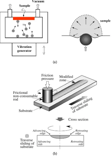
Figure 2. (a) Schematic illustration of the SMAT process set-up and the repeated multidirectional plastic deformation in the sample’s surface layer [17]. (b) Schematic illustration of FTMP for surface modification [18]. 26 Figure 3. Microstructure of electrodeposited NC Ni sample [19]. 27 Figure 4. Variation in the subgrain diameter with strain in some Al alloys [24]. 28 Figure 5. Rotation of cells in Cu as a function of depth bellow the wear surface after 1
cycle and 100 cycles of sliding [25]. 29
Figure 6. Schematic drawing of grain subdivision in small and large strains. DDW
represents dense dislocation walls [27]. 30
Figure 7. (a) TEM micrograph of the dislocation microstructure developed during cold rolling in pure Ni. Viewing plane is ND/RD section. The rolling direction is marked RD [29]. (b) Schematic drawing of a large strain dislocation structure showing sheets of extended LBs with IDBs bridging between them. High-angle LBs are represented by thick lines. Intercept spacings of LBs (DGNB)
and of cell boundaries (DIDB) are shown [29]. 31
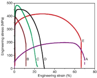
Figure 8. Stress-strain curves for pure Cu. A: annealed; B: 95% room-temperature rolled; C: 93% liquid-nitrogen-temperature rolled; D: the same as C but heat treated in 180 ºC for 3 min; E: the same as C but heat treated in 200 ºC for 3
min [8]. 32
Figure 9. Grooved pattern of the shark skin surface [67]. 33
Figure 12. (a) SEM micrographs of the surface and the cross section of the pads of cricket [9]. (b) Shape of the pad in static conditions (top) and during the motion in proximal and distal directions [67]. (c) Formation of anisotropic mechanical interlocking as a result of flexibility and orientation [67]. 36
Figure 13. 3D topography of the skin of carpet python [73]. 37
Figure 14. (a) The hierarchical structure of a water strider’s leg with numerous oriented microsetae. (b) Each seta has a nanoscale grooved surface texture [76]. 38 Figure 15. (a) Microscale protuberances on the surface of a lotus leaf. (b) Each
protuberance is covered with a nanoscale needle-like structure. 39
CHAPTER 2
Figure 1. The XRD patterns of: (a) the MC Ni, and (b) the NC Ni. 58
Figure 2. A bright field TEM image of the NC Ni. 59
Figure 3. Variations in the COFs of: (a) the MC Ni, and (b) the NC Ni, in air (35% RH). 60 Figure 4. (a) Variations in volume loss with sliding cycles for the MC Ni and the NC Ni
in air (35% RH). (b) Variations in initial wear rate with sliding cycles under the same conditions. (c-f) Corresponding initial and steady-state surface
damage profiles as marked in (a). 61
Figure 5. (a,b) Optical micrographs of the MC Ni wear tracks formed after 8 and 103 sliding cycles in air (35% RH). (c) SEM micrograph of the track shown in (b).
(d) EDS spectra of the area labelled 1 in (c). 62
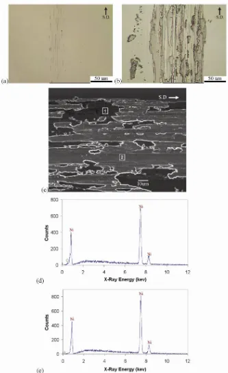
Figure 6. (a,b) Optical micrographs of the NC Ni wear tracks formed after 8 and 103 sliding cycles in air (35% RH). (c) SEM micrograph of the track shown in (b). (d) EDS spectra of the area labelled 1 in (c). (e) EDS spectra of the area
labelled 2 in (c). 63
Figure 7. Microhardness values of the original and worn surfaces of the MC Ni and NC Ni after 8, 60, 200, and 103 sliding cycles in the air and argon atmospheres.
All measurements were made under 10 gf normal load. 64
same conditions. (c-f) Corresponding initial and steady-state surface damage
profiles as marked in (a). 66
Figure 10. (a,b) Optical micrographs of the MC Ni wear tracks formed after 8 and 103 sliding cycles in dry argon. (c) SEM micrograph of the track shown in (b). (d)
EDS spectra of the area labelled 1 in (c). 67
Figure 11. (a,b) Optical micrographs of the NC Ni wear tracks formed after 8 and 103 sliding cycles in dry argon. (c) SEM micrograph of the track shown in (b). (d) EDS spectra of the area labelled 1 in (c). (e) EDS spectra of the area labelled 2
in (c). 68
CHAPTER 3
Figure 1. XRD patterns of: (a) the MC Ni, and (b) the NC Ni. 87
Figure 2. A bright field TEM image of the NC Ni. 88
Figure 3. (a) Load-depth curves of typical nanoindentations on the MC Ni and NC Ni samples. (b) Variations in nanohardness value with indentation contact depth under load for the MC Ni and NC Ni. The last point in each series of data represents the nanohardness value calculated after complete unloading. 89 Figure 4. Wear rate vs. sliding speed for the MC Ni and NC Ni after 8 sliding cycles in
the argon atmosphere. 90
Figure 5. Variations in the COFs during 8 sliding cycles in the argon atmosphere at different speeds for: (a) the MC Ni, and (b) the NC Ni. 91 Figure 6. The average COFs of the MC Ni and NC Ni plotted as a function of sliding
speed. 92 Figure 7. (a-c) 3-D surface profiles of the MC Ni’s wear tracks after 8 sliding cycles in
the argon atmosphere at speeds of (a) 0.2×10⁻² m/s, (b) 0.8×10⁻² m/s, and (c) 3.0×10⁻² m/s. (d-f) 3-D surface profiles of the NC Ni’s wear tracks after 8
Figure 9. Microhardness values obtained from the wear tracks formed on the surfaces of the MC Ni and NC Ni at different sliding speeds. The data points at the velocity of 0 represent the microhardness values of the original surfaces prior to the wear tests. All measurements were made using a 0.1 N normal load. 95 Figure 10. (a) Variations in wear rates of Ni samples with original microhardness at
different sliding speeds. The legend shows the Archard-type equations that best fit the experimental data. (b) Variations in K (in Equation 9) with sliding speed. (c) Variations in α (in Equation 9) with sliding speed. 96
CHAPTER 4
Figure 1. Secondary electron SEM surface images of (a) the NC Ni-MP SiC coating,
and (b) the NC Ni-NP SiC coating. 108
Figure 2. The main steps in preparing TEM samples using the “lift-out” FIB technique. (a) Two narrow trenches were ion-milled on both sides of the area of interest, protected by a carbon layer, to obtain a 1 µm thick plate. (b) A tungsten needle was positioned near the plate. (c) A thin layer of carbon was deposited on the interface of the plate and the needle to attach them together. (d,e) The plate was then lifted out, and (f) it was milled to a final thickness of about 100
nm using a low ion beam current of 10 pA. 109
Figure 3. (a-c) Contact surface morphologies formed after sliding for 500 cycles at 298 K on: (a) NC Ni film, (b) NC Ni-MP SiC coating, and (c) NC Ni-NP SiC coating. (d-f) The contact surface morphologies formed after sliding for 500 cycles at 493 K on: (d) NC Ni film, (e) NC Ni-MP SiC coating, and (f) NC
Ni-NP SiC coating. 110
Figure 4. The wear rates of the unreinforced NC Ni and the composite NC Ni coatings measured after sliding for 500 cycles at 298 and 493 K. 111 Figure 5. (a-c) Variations in COFs at 298 K for: (a) NC Ni film, (b) NC Ni-MP SiC
Figure 7. (a-c) Cross-sectional FIB images of the wear tracks formed after sliding for 500 cycles at 298 K on: (a) NC Ni film, (b) NC Ni-MP SiC coating, and (c) NC Ni-NP SiC coating. (d-f) Cross-sectional FIB images of the wear tracks formed after sliding for 500 cycles at 493 K on: (d) NC Ni film, (e) NC Ni-MP SiC coating, and (f) NC Ni-NP SiC coating. S.D.: sliding direction; D.L.:
deformed layer; T.L.: tribolayer. 114
Figure 8. Bright-field and dark-field cross-sectional TEM images of the deformed layers formed after sliding for 500 cycles at 493 K on: (a,b) unreinforced NC
Ni coating, and (c,d) NC Ni-NP SiC coating. 117
Figure 9. A high resolution TEM image of the subsurface microstructure in the unreinforced NC Ni tested at 493 K shows new grains recrystallized at grain
boundaries during the high temperature wear test. 119
CHAPTER 5
Figure 1. Variations of COF with sliding cycles in the MC Co and NC Co. 125 Figure 2. (a) Variation of volume loss with sliding cycles for the MC Co and NC Co.
(b) Variations of wear rate with sliding cycles for the MC Co and NC Co. 126 Figure 3. Optical surface profiles of the wear tracks after 1000 sliding cycles on: (a)
MC Co, and (b) NC Co. 127
Figure 4. Optical micrographs of the wear tracks after 1000 sliding cycles on: (a) MC
Co, and (b) NC Co. 128
Figure 5. SEM micrographs and typical EDS spectra of the tribolayers formed on top of the wear tracks after 1000 sliding cycles for: (a) MC Co, and (b) NC Co. 129
CHAPTER 6
the top of the acetate film. (d): The acetate film is dissolved in acetone to
obtain a free-standing replica of the biotexture. 141
Figure 2. (a): An SEM microgragh of the surface texture of the lotus leaf. (b): An SEM micrograph of the negative impression of the leaf’s texture on acetate film. (c): An SEM micrograph of the NC Ni replica of the lotus leaf. (d): A high magnification SEM micrograph of the texture shown in (c). (e): An optical 3-D profile of the NC Ni replica’s surface. (f): A bright field TEM image of the
NC Ni film. 142
Figure 3. (a): The contact surface morphology of the NC Ni replica of the lotus leaf after 200 sliding cycles. The protuberance tips were flattened, and needle-like debris was scattered in the spaces between the protuberances. (b): A high magnification SEM micrograph of the texture shown in (a). 143 Figure 4. Variation of COF with sliding cycles measured on the NC Ni replica of the
lotus leaf and the flat NC Ni film. 144
Figure 5. An optical micrograph of the worn surface of the flat NC Ni film after 200
sliding cycles. Arrows show tribolayers. 145
Figure 6. (a): An optical 3-D profile of the red tail boa’s skin surface. The head-to-tail direction (H-T) is marked with a solid arrow, while the lateral direction (L) is shown with a dotted arrow. (b): An SEM micrograph of the boa’s skin surface texture. (c): An SEM micrograph of the negative impression of the skin’s texture on an acetate film. (d): An SEM micrograph of the NC Ni replica of the boa’s skin. (e): A typical optical 2-D profile of the texture shown in (d). 146 Figure 7. Average COFs of the NC Ni replica of the boa’s skin measured in three
different directions corresponding to the head-to-tail, tail-to-head and lateral
directions. 147
CHAPTER 7
conductive surface. (c): A layer of NC Ni was electrodeposited on the acetate film. (d): The acetate film was dissolved in acetone to obtain a free-standing replica of the lotus leaf, and then a short-duration SED process was applied to deposit “Ni crowns” on the protuberances’ tips. (e): A PFPE solution treatment of the surface created a nanotextured layer on the “Ni crowns”. 164 Figure 2. (a): An SEM micrograph of the surface texture of a carbon-coated lotus leaf.
(b): The needle-like nanotexture covering the surface of a protuberance on the lotus leaf. (c): A negative impression of the lotus leaf’s surface texture on a cellulose acetate film. (d): A higher magnification image of a protuberance’s impression on the acetate film shown in (c). (e): NC Ni replica of the acetate film obtained by the PED process. (f): A higher magnification image of a
protuberance on the NC Ni replica shown in (e). 165
Figure 3. (a): A cross-sectional FIB image of a protuberance on the NC Ni lotus leaf replica (S1). (b): A bright field TEM image of the cross-section of the NC Ni deposits at the tip of a protuberance. The inset shows the corresponding SAD
patterns. 166 Figure 4. (a): A BSE image of the NC Ni lotus leaf replica after PFPE solution
treatment (S2). (b): SE image of the surface shown in (a). (c): A higher magnification SE image of a protuberance on the surface shown in (b). 167 Figure 5. (a): A BSE image of the NC Ni lotus leaf replica after 120 s of SED process
Figure 7. (a) A cross-sectional FIB image of a protuberance on the lotus leaf replica after 120 s of SED process and the PFPE solution treatment (S4), which reveals the microstructures of the protuberance and its “Ni crown”. (b): A cross-sectional FIB image of a protuberance on the lotus leaf replica after 300 s of SED process and the PFPE solution treatment (S6), which reveals the microstructures of the protuberance and its “Ni crown”. 170 Figure 8. (a) Comparison of the water contact angles and the shapes of the water
droplets on the NC Ni surfaces. S1: NC Ni lotus leaf replica; S2: S1 after the PFPE solution treatment; S3: NC Ni lotus leaf replica after the 120 s SED process; S4: S3 after the PFPE solution treatment; S5: NC Ni lotus leaf replica after the 300 s SED process; S6: S5 after the PFPE solution treatment; S7: NC Ni deposited on smooth replica surface; S8: S7 after the PFPE solution treatment. (b): An optical image of a large water droplet on the surface of S4. 171 Figure 9. (a): An SE image of the wear track formed on the NC Ni lotus leaf replica
(S1) after sliding for 500 cycles. A trench has been milled at the centre of this area to reveal a protuberance’s cross-section parallel to the sliding direction for microstructural analysis by FIB. (b): A cross-sectional FIB image of the
worn protuberance shown in (a). 172
Figure 10. COF vs. sliding cycle curves of: (a): NC Ni lotus leaf replica (S1). (b): S1 after the PFPE solution treatment (S2). (c): NC Ni lotus leaf replica after 120 s of SED process (S3). (d): S3 after the PFPE solution treatment (S4). (e) NC Ni lotus leaf replica after 300 s of SED process (S5). (f): S5 after the PFPE solution treatment (S6). (g): NC Ni deposited on smooth replica surface (S7).
(h): S7 after the PFPE solution treatment (S8). 173
Figure 11. The average steady-state COFs of the NC Ni surfaces. S1: NC Ni lotus leaf replica; S2: S1 after the PFPE solution treatment; S3: NC Ni lotus leaf replica after the 120 s SED process; S4: S3 after the PFPE solution treatment; S5: NC Ni lotus leaf replica after the 300 s SED process; S6: S5 after the PFPE solution treatment; S7: NC Ni deposited on smooth replica surface; S8: S7
LIST OF ABBREVIATIONS
ARB accumulative roll-bonding
ASTM American society for testing and materials
BSE backscattered electron
COF coefficient of friction COFp peak coefficient of friction
COFss steady-state coefficient of friction
CVD chemical vapour deposition DSC differential scanning calorimetry ECAP equal channel angular pressing EDS energy dispersive spectroscope
FCC face centred cubic
FIB focused ion beam
FTMP friction thermomechanical processes
GB grain boundary
HCP hexagonal close-packed
HPT high pressure torsion
HV Vickers microhardness
IDB incidental dislocation boundaries
LB lamellar boundaries
MC microcrystalline
MEMS micro-electro-mechanical systems MP SiC microparticles of SiC
NC nanocrystalline NP SiC nanoparticles of SiC
RH relative humidity SAED selected area electron diffraction
SE secondary electron
SED secondary electrodeposition
SEM scanning electron microscopy
SMAT surface mechanical attrition treatment SPD severe plastic deformation
TEM transmission electron microscopy
USSP ultrasonic shot peening
NOMENCLATURE
ac radius of projected contact area
ac′ actual radius of projected contact area
A′ cross-sectional area of indentation Areal real area of contact
BM half peak breadth
BS instrumental broadening
c2 dimensionless parameter to account for oiling-up and sinking-in C effective elastic modulus
d grain size
D counterface ball diameter
E elastic modulus
f frictional force
fair fractional contact area between liquid and air
fS fractional contact area between liquid and solid
h indentation depth immediately before partial unloading
hc indentation contact depth
hc′ actual indentation contact depth
hf residual depth after complete unloading of indenter
hi indentation depth extrapolated to zero load along linear fit of upper
one-third of unloading curve hmax maximum indentation depth
H hardness
H0 single crystal hardness
k constant for grain boundary strengthening
rind indenter radius
R wear track radius
S shear component of frictional force
v sliding speed
V volumetric wear loss
w wear track width
W wear rate
W0 grain-size independent component of wear rate
α wear exponent
γsv solid-vapour surface energy
γsl solid-liquid surface energy
γlv liquid-vapour surface energy
δ elastic depth recovery ratio
θ peak’s Bragg angle (Chapters 2,3); actual contact angle (Chapter 7)
θT thermodynamic contact angle
λ X-ray wavelength
μ coefficient of friction
ν Poisson’s ratio
σ0 lattice frictional stress
σH Hertzian stress
σy yield strength
CHAPTER 1
INTRODUCTION
1. GENERAL OVERVIEW
Nanocrystalline (NC) materials provide great potential for improving the performance
and extending the capabilities of products in many industrial sectors, because of novel
properties that mostly originate from a large volume fraction of grain boundaries [1-3]. It
is known that dislocation nucleation and motion are both necessary for plastic
deformation, but activation of dislocations in grains smaller than 100 nm can be difficult.
As a result, the mechanical behaviour of NC materials is characterized primarily by high
strength and hardness [4-7], and limited ductility [7,8].
The increase in strength and hardness that accompanies grain refinement is appealing
from the tribological point of view, particularly when designing new materials and
surfaces with improved friction and wear properties. There is a clear need for
experimental work to characterize micromechanisms of wear in NC materials, and to
rationalize microscopic processes leading to generation of wear debris or surface damage.
In examining the wear behaviour of NC materials attention should be given to the role of
testing atmosphere as the NC materials have a larger density of grain boundaries that can
comprehensive analysis. In addition, the large fraction of grain boundaries in NC
materials may make these materials unstable at elevated temperatures, and therefore, it is
important to also investigate the wear mechanisms of these materials at elevated
temperatures. More details on the effects of surface oxidation, strain-rate sensitivity and
thermal instability on the tribological performance of NC materials are presented in
Section 2 of this chapter.
On the other hand, it is known that biological organisms maintain their unique surface
properties by employing mechanisms that cannot be explained using simple linear
theories of friction and adhesion. The complex surfaces of these organisms are capable of
controlling friction, adhesion and wettabilty through a combination of surface structure,
surface chemistry, flexibility, and active interface control [9]. Hence, adapting these
mechanisms for fabricating novel engineering surfaces with enhanced properties (such as
superhydrophobicity and low friction) is a promising technological trend. The challenge,
however, is how to combine the advantages of a hard, wear-resistant material with the
exceptional hydrophobicity or frictional properties of a biological organism in a single
surface designed to function in an engineering system.
The current study proposes a method for producing a new group of wear-resistant
materials with superhydrophobic surfaces and controlled frictional properties, by
combining the high strength and hardness of NC materials with the surface texture of
certain biological systems. The proposed method consists of two steps:
i) replication of the biological surface texture on a cellulose acetate film to obtain a
ii) electrodeposition of the NC material on the acetate film to obtain a hard replica of
the biological surface texture.
The result is a self-sustaining NC film with a surface texture that simulates that of the
selected biological system.
Along these lines, this dissertation is organized in eight chapters. Chapter 1 is an
introduction to the entire dissertation that starts with a general overview and an outline of
the objectives and methodologies used in the following chapters. It then reviews the main
methods for the production of NC materials and the microstructure’s role in mechanical
and tribological behaviour of these materials. This chapter also presents examples of
biological systems in which friction, adhesion and wettability are controlled through
adaptation of specific surface textures.
Chapter 2 characterizes friction and wear mechanisms of an NC Ni in comparison
with an MC Ni, to understand the micromechanisms responsible for the NC Ni’s
tribological behaviour. Coefficients of Friction (COF) and wear rates are measured in
ambient air and argon environments using a pin-on-disc tribometer. The role of the
oxide-rich tribolayers in the friction and wear mechanism of this NC metal is delineated, and
microscopic processes leading to generation of wear debris and surface damage in
different testing environments are characterized in detail.
The sliding-speed dependence of the COFs and the wear rates of the NC Ni and the
Chapter 4 reports on the production of NC Ni composite coatings reinforced with
micro and nanoparticles of SiC. The objective of this chapter is to investigate whether
SiC particles as reinforcements could improve the high-temperature friction and wear
properties of NC Ni. The COFs and wear rates of the NC Ni coatings reinforced with the
SiC particles are measured at 298 and 493 K, using a high-temperature pin-on-disc
tribometer. The cross-sectional microstructures of the worn surfaces are studied using
focused ion beam (FIB) and transmission electron microscopy (TEM) techniques.
Chapter 5 presents a study of the tribological behaviour of NC Co as a metal with a
lattice structure that differs from that of the NC Ni. The friction and wear properties of an
NC Co are studied in comparison with an MC Co using pin-on-disc tests in ambient air.
Chapter 6 details the method developed in this research to produce NC Ni films with
the surface textures similar to those of biological systems. The objective of this chapter is
to produce hard replicas of certain biological surfaces to reduce or control the friction.
For this purpose, two types of biological surface textures (i.e., a lotus leaf and a boa’s
skin) are replicated on a cellulose acetate film, on which an NC Ni coating is
electrodeposited to obtain self-sustaining replicas of the biotextures. The frictional
properties of the NC Ni lotus leaf replicas are measured using a pin-on-disc tribometer.
The COFs of the NC Ni snake skin replicas are measured using an instrumented
microscratch tester with a Rockwell-type diamond indenter tip.
Chapter 7 explains the fabrication of biotextured NC Ni films with superhydrophobic
and low friction surfaces. NC Ni replicas of lotus leaf are produced using replication and
electrodeposition methods described in Chapter 6. A short-duration, secondary
followed by a perfluoropolyether (PFPE) solution treatment. Water contact angles and
COFs of the textured films are measured and compared to those of smooth NC Ni
surfaces.
The final chapter of this dissertation, Chapter 8, is a summary of the preceding
2. NANOCRYSTALLINE MATERIALS
2.1. Production of Nanocrystalline Materials
NC materials can be produced using a large number of methods that include
electrodeposition, severe plastic deformation (SPD), crystallization of amorphous solids,
consolidation of nanopowders, physical vapour deposition (PVD) and chemical vapour
deposition (CVD). Among these methods, electrodeposition and SPD techniques are
widely used in the production of dense NC metals.
Electrodeposition
Electrodeposition can be used to produce NC metals with a controlled grain size [10].
The processing parameters for this method include the electrolyte’s basic chemical
composition, the addition of grain nucleators, stress relievers and grain-growth inhibitors,
the PH value, the deposition temperature, the current density, and the type of current
cycles [10,11].
Electrodeposition can be used with conventional or modified electroplating baths to
produce large parts with sufficient thickness in hours. The specimens produced by this
method are fully dense, and their textures can be controlled through the process
parameters. It is a relatively inexpensive, room-temperature technology that can easily be
developed for mass production [12].
The main disadvantage of this method, however, is the limited thickness of the
Severe Plastic Deformation
Very large deformations can be obtained by using SPD methods at relatively low
temperatures [13], which create complex stress states, straining patterns and dislocation
configurations, in addition to high densities of the geometrically necessary dislocations
that lead to grain refinement [8].
High pressure torsion (HPT), equal channel angular pressing (ECAP), and
accumulative roll-bonding (ARB) are the best-known methods for providing large plastic
deformations and nanostructure formations. Schematics of these techniques are presented
in Figures 1a-c. For many metals, these methods can lead to grains as fine as 20 nm and
dislocation densities as high as 5×10¹⁴ m-2 [14].
An NC surface layer can be produced without affecting bulk properties, by limiting
the extent to which plastic deformation is applied to a material’s surface. The techniques
employed to achieve this goal are generally referred to as surface nanocrystallization, and
include ultrasonic shot peening (USSP) [15], surface mechanical attrition treatment
(SMAT) [16,17], and friction thermomechanical processes (FTMP) [18].
Lu et al. [17] placed spherical steel balls with smooth surfaces and a diameter of 8
mm into a reflecting chamber that was oscillated by a vibration generator. The system’s
high frequency (20 kHz) means that the surface is impacted by a large number of flying
balls over a short period of time (Figure 2a). The repeated, multidirectional impacts
Shinoda et al. [18] modified the surfaces of some Al alloy castings using an FTMP
technique, in which a non-consumable rod is forced against the specimen’s surface while
rotating (Figure 2b). The frictional force introduces stress into the surface, and the
frictional heat makes it plasticise. As a result, the microstructure is refined due to
dynamic recrystallization. According to their observations, the porosity in the modified
layer was completely removed, the segregation of Cu and Si was considerably reduced,
and the hardness of the surface layer increased due to grain refinement during the FTMP.
2.2. Microstructure of Nanocrystalline Materials
Microstructure of Nanocrystalline Metals Produced by Electrodeposition
Finer microstructures and higher dislocation densities can be obtained through
electrodeposition, compared to SPD techniques [19]. Depending on the application of the
NC material, it is possible to modify the processing parameters to enhance the
microstructural characteristics. For example, instead of adding grain refiners like
saccharin, which usually results in a high concentration of sulphur in the deposits [20], it
is possible to prevent grain growth by rotating the substrate at a high speed [21].
Electrodeposited NC metals and alloys are usually textured, and contain microstrain
in their crystalline lattice [21]. The texture mainly depends on the composition of the
material and the processing parameters, such as the type of current cycle [21]. In contrast,
the microstrain is proportional to the deposit thickness [12]. These microstructural
features can be measured using X-ray diffraction (XRD) technique [22].
The relationship between the crystalline structures of the electrodeposited NC
grain morphology [23]. For example, the slight mismatch between the lattice constants of
Cu (substrate) and Ni (deposit) produces a characteristic lamellar structure that consists
of micro-twins within the grains [23]. No micro-twins have been observed in
electrodeposited Ni or Cu on a Ti substrate, because the lattice constants and crystal
structure of the deposits and substrate are so different [23]. Figure 3 shows the
microstructure of an electrodeposited NC Ni sample [19].
Microstructural Evolution in Severe Plastic Deformation Methods
Lloyd et al. [24] investigated the structure of some heavily cold-worked Al alloys,
and observed the evolution of a subgrain structure as they increased the strain in the
studied alloys. According to their report, the subgrain size decreased sharply up to a
strain of 1.0, and then more slowly over the subsequent strain range. Figure 4 shows the
variation in the subgrain diameter with strain in different Al alloys. They also reported a
misorientation in the range of 2-20 degrees across subgrains at the largest strains (2.5),
but did not present a detailed analysis of the misorientation distribution with strain.
Heilmann et al. [25] employed a block-on-ring test configuration to determine the
orientation of subsurface cells generated by sliding in Cu. They observed large plastic
strains and large rotation angles in subsurface cells after very short sliding distances.
According to their report, after a sliding distance of 12 m (100 cycles) under a normal
became wider, misorientation between the adjacent cells decreased, and dislocation
networks appeared within the cells. They also observed and measured the rotation of the
cells (as a result of surface deformation) around an axis normal to the sliding direction
and parallel to the interface. The cell rotation was maximum at the interface, and
increased as the number of sliding cycles increased. Figure 5 shows the cell rotation as a
function of the subsurface depth after 1 cycle, and then after 100 cycles of sliding [25].
It has been suggested that high strains introduce a lamellar or subgrain structure with
boundaries of different misorientation angles [26]. Experiments have shown that
deformation-induced, high-angle boundaries are common to a diverse set of materials and
conditions [27]. A detailed description of the microstructural evolution during SPD of
metals has been presented by Hughes et al. [27]. They employed convergent beam
Kikuchi patterns to assess the orientations of individual crystallites, and found that the
ratio of the deformation-induced, high-angle boundaries to the original grain boundaries
was significantly large.
Figure 6 provides a schematic drawing of grain subdivision in small and large strains
[27]. According to this figure, increasing the strain prompts dislocation boundaries to
evolve from a typical cell block structure into a lamellar structure that is oriented in the
direction of material flow. Continued deformation leads different slip system
combinations to operate within each original grain, resulting in dislocation accumulation
processes. As a result, complex dislocation boundaries form, and grains subdivide into
regions with different texture components [27]. Increasing the strain leads to the rotation
of these small individual crystallites towards the preferred end textures [28]. Since the
formation of high-angle boundaries. Therefore, grain subdivision followed by texture
evolution can result in a large fraction of high-angle boundaries in a severely deformed
metal, which produces a deformation-induced grain refinement [27].
Figure 7a shows a TEM micrograph of the dislocation microstructure developed
during cold rolling in pure Ni. A well-developed structure of lamellar boundaries and cell
blocks has formed after a 90% cold reduction [29]. Figure 7b shows a schematic drawing
of a large-strain dislocation structure that features sheets of extended lamellar boundaries
(LB) with incidental dislocation boundaries (IDB) bridging between them [29].
2.3. Properties of Nanocrystalline Materials Influencing Tribological Behaviour
Strength, Ductility and Strain-Rate Sensitivity
Since the early works of Hall [30] and Petch [31], experiments have shown that
reducing the grain size of metals and ceramics increases their yield strength, according to
the well-known Hall-Petch equation:
5 . 0 0 − + = kd y σ
σ (1)
where σ0 is the lattice frictional stress, d is the grain size, and k is a constant for the grain
boundaries’ contribution to the strength.
Since the hardness (H) is related to the yield strength (σy) of the material, by [32]:
y
H =3σ (2)
the hardness and the grain size of the NC Al obeyed the Hall-Petch equation, much like
other polycrystalline materials. More specifically, the grain boundaries continued to
contribute to the material’s strength, even down to grain sizes as small as 15 nm. Other
studies [33-36] on the hardness of NC materials have shown an increase in hardness by a
factor of 5-7 when the grain size decreased from the micrometer range to the nanometer
range. However, the Hall-Petch relationship is only valid down to a critical grain size of
about 14 nm [33,37]. Below this critical grain size, each grain cannot contain more than
one dislocation, and therefore the dislocation pile up mechanism is not applicable [37].
Therefore, the mechanical properties of NC materials are mainly controlled by the
grain-boundary-induced deformation mechanisms rather than by the plasticity of the crystals
due to dislocation movement [38,39]. It is also important to note that the strength of
nanostructured materials is determined not only by crystallite size, but also by
misorientation across the crystallite boundaries [40].
Since microstructural refinement leads to a great improvement in a material’s
hardness, one can expect an improvement in the wear resistance as well, according to
Archard’s law of wear [41]:
H P K
W = (3)
where W is the volume of material worn per unit sliding distance (wear rate), P is the
applied load, H is the hardness, and K is the wear coefficient. The literature has
thoroughly documented that both the coefficient of friction (COF) and the wear rate are
lower in specimens with higher surface hardness values [16,37,42], because as the
reduced so that the contacting solids can slide with a reduced amount of energy
expenditure [16,42]. As a result, both the COF and the surface damage decrease.
While, the COF peak and the severe wear rate at the initial stage of sliding are usually
higher in softer materials, the steady-state COF and wear rate are less sensitive to the
hardness of the original surface, because the formation of hard tribolayers increases the
surface hardness at the later stages of sliding [43,44].
NC materials often exhibit low tensile ductility at room temperature, which limits
their applications, but experiments have shown that NC materials with high tensile
ductility can be produced using the SPD techniques [8,39]. For example, a 30% uniform
elongation and 65% elongation to failure were observed when samples of pure Cu were
subjected to a special thermo-mechanical treatment (Figure 8) [8]. This treatment resulted
in a bimodal grain size distribution with microcrystalline (MC) grains embedded inside a
matrix of NC grains. According to the Hall-Petch relationship, the NC matrix provides
the high strength of the material [42,45]. Meanwhile, the MC grains induce strain
hardening mechanisms [46,47] that lead to a high tensile ductility.
Zhang et al. [39] measured the tensile ductility of NC Zn, and reported a relatively
high tensile ductility compared to an MC Zn. According to their report, the high tensile
ductility probably originated from the strain accumulating potential of the larger grains,
and the grain boundary sliding mechanism of the smaller grains. They suggested several
Surface ductility is an important factor in determining the wear resistance of a
material [48]. It is widely accepted that delamination wear is usually associated with
subsurface crack propagation [49]. Alpas and Embury [50] reported that crack initiation
and propagation along the shear bands was the main mechanism of delamination wear in
ductile materials. This mechanism can play an important role in the wear behaviour of
NC materials produced by the SPD methods, because shear bands form during the
microstructural evolution in these materials [27].
Plastic deformation mechanisms in NC materials, include grain boundary sliding and
dislocation emission at grain boundaries [22,51-53]. Since these mechanisms are
time-dependent, the deformation of NC materials becomes increasingly difficult at higher
strain rates, leading to notable enhancements in yield strength [54-58]. An increase in the
sliding speed is expected to cause an increase in the rate of the application of the shear
strain to the contact surface. This suggests that a slight change in sliding speed may have
a great influence on the tribological properties of NC materials. The role of sliding speed
on the friction and wear behaviour of NC Ni is explored in Chapter 3.
Surface Oxidation and Thermal Instability
NC materials have a larger density of grain boundaries that act as preferential
nucleation sites for oxides and provide preferential diffusion paths for oxygen [59]. As a
result, NC materials are expected to possess higher rates of surface oxidation. Therefore,
surface oxidation during sliding wear may play a substantial role in tribological
friction and wear mechanisms of electrodeposited NC Ni and NC Co is discussed in
Chapters 2 and 5.
In spite of their higher oxidation rates, NC materials usually display a lower average
corrosion rate, as they are less susceptible to localized intergranular corrosion and pitting,
compared to their MC counterparts [59-63]. It has been suggested that [60] the large
density of grain boundaries in NC materials reduces the distance between the anodic
(grain boundary) and the cathodic (grain interior) sites, resulting in lower localized
corrosion potentials, and hence, a more uniform corrosion and passivation of the surface.
NC materials generally possess a low thermal stability [64,65]. This property
originates from the large amount of energy stored in the microstructure of these materials,
which becomes a driving force for recovery and recrystallization at elevated
temperatures. This restricts the tribological applications of NC materials to
low-temperature environments, as well as low-to-medium sliding speed range where the
surface temperature is below the temperature at which the material becomes thermally
instable. The thermal stability of NC materials can be improved by annealing the material
below its recrystallization temperature, solid solution strengthening, and precipitation
strengthening [64,66]. Effect of thermal instability on the friction and wear behaviour of
electrodeposited NC Ni is discussed in Chapter 4, where it is shown that the
high-temperature wear resistance of NC Ni could be improved through dispersion
3. TRIBOLOGICAL PROPERTIES OF BIOLOGICAL SYSTEMS RESULTING
FROM SURFACE TEXTURE
The properties mentioned in Section 2.3 have significant effects on the tribological
behaviour of a smooth NC surface. In this section, the tribological properties of
biological systems with much softer surfaces and the effects that various surface textures
have on them are explored. These surface textures display similar effects if applied to
hard NC systems, as discussed in Chapters 6 and 7.
3.1. Low-Friction Surfaces
Shark skin is a good example of biological surfaces that maintain a low friction with
the surrounding environment. The surface texture of shark skin reduces the turbulence of
water in the solid/fluid boundary, resulting in a reduction in the friction between the
water and the shark’s body. Figure 9 shows the surface texture of a shark skin [67]. The
skin consists of hard, tooth-like scales with spines that point backward. The surface of
these small scales is covered with microscale grooves that lie parallel to the longitudinal
body axis. This special structure allows water to flow along the shark’s body with
minimum friction, and it reduces the adhesion of marine species to the skin [68].
Based on the structure of shark skin, industrial applications have been developed to
decrease drag resistance in airplanes and boats. For example, applying a vinyl tape with
tiny v-shaped grooves to the surface of airplane and boat hulls can alter the character of
the air and water flow inside the boundary layer, resulting in a reduction in the friction
3.2. High-Friction Surfaces
Increasing Friction by Utilizing van der Waals Forces
The gripping foot of a gecko is probably the best biological example for utilizing van
der Waals forces. Capable of climbing smooth vertical surfaces, the gecko has about
5×10⁵ keratinous hairs (setae) on each foot. Each seta has a length of 30-130 μm and
features hundreds of pads at its end (Figure 10a) [69,70].
Autumn et al. [70] studied the adhesive force of a single gecko foot-hair, and
concluded that hundreds of pads at the end of each seta interact on a molecular level with
any surface. This creates a strong adhesion as a result of van der Waals forces. The gecko
releases its foot by peeling off the hairs at a critical angle.
Based on the gecko’s mechanism for increasing friction, Geim et al. [71] developed a
microfabricated polyimide dry adhesive (Figure 10b). The surface of this material is
covered by submicron, aligned posts that simulate the keratinous hairs on a gecko’s foot.
Increasing Friction by Utilizing Mechanical Interlocking
Many biological systems employ mechanical interlocking mechanism to increase
adhesion and friction. This mechanism is found in various types of barbs and hooks [67].
The wing-locking devices in tenebrionid beetles are good examples of surfaces that
use this mechanism to increase the friction (Figure 11a) [72]. Examples of possible
3.3. Surfaces with Anisotropic Frictional Properties
In the evolutionary process, some moving organisms have been optimized to
minimize friction at one end of the system while maximizing it at the other end [67].
Anisotropic interlocking is an important mechanism employed by some biological
systems to control frictional forces in different directions. The pad of a cricket’s foot that
attaches this insect to a variety of surfaces is a good example of natural surfaces that
utilize the anisotropic interlocking mechanism. Scherge et al. [9] carried out a
comprehensive study on the attachment pads of cricket. Figure 12a shows SEM
micrographs of the surface and the cross-section of the pad [9]. The micrographs reveal
that the angle between the pad surface and the direction of its hairs is less than 90º,
making the friction between the pad and various surfaces anisotropic. This is better
understood by considering Figure 12b, which shows the shape of the pad in static
conditions, and during motion in proximal and distal directions [67]. It should be noted
that the anisotropy in this system increases when normal load increases [9]. In addition,
the flexibility of the pads enables them to adapt quickly to any surface profile [9]. Figure
12c shows how a combination of flexibility and orientation forms a self-mating
mechanical contact that creates an anisotropic interlocking mechanism.
The nanoscale design of snake skin is another biological example that uses an
anisotropic interlocking mechanism to adjust the friction in different directions [73]. In
this example, ordered directional texture causes a frictional anisotropy that enhances
forward motion while simultaneously serving as an effective halt to backward motion. As
Figure 13 [73] shows, this frictional anisotropy in forward/backward motions is a result
micro-obstacles cannot prevent forward motion because of the high flexibility of the
microfibrils [73].
The fabrication of an NC Ni replica of a snake skin is described in Chapter 6. This
type of structure may have potential applications in engineering systems, where a range
of different COF values in various directions in needed.
3.4. Superhydrophobic Surfaces
Superhydrophobicity is critical to the survival of many insects. Some insects, like
butterfly [74] and cicada [75], use superhydrophobicity to keep their wings dry and clean.
Other insects, like the water strider [76], have superhydrophobic legs that enable them to
support themselves on the surface of the water. The hierarchical structure of a water
strider’s leg, with its numerous oriented microsetae, is shown in Figure 14a. Each seta
has a nanoscale grooved surface texture, as seen in Figure 14b. This multilevel surface
texture allows the water strider to entrap a very high fraction of air at the leg/water
interface. This interfacial air cushion prevents the legs from becoming wet, and helps the
insect to overcome the gravity.
Plant leaves provide the best-known examples of water-repellent surfaces in nature.
The ability to remove water from its surface cleans the leaf, and minimizes the risk of
infection to the plant [68]. One of the most-studied examples of this phenomenon is the
droplets, creating a surface with a water contact angle greater than 150° [77]. A more
detailed account of the wettability principles is presented in Chapter 7, where the
fabrication of an NC Ni lotus leaf replica with a superhydrophobic surface and low COF
REFERENCES
[1] H. Gleiter, Progr. Mater. Sci. 33 (1989) 223. [2] C. Suryanarayana, Int. Mater. Rev. 40 (1995) 41. [3] K. Lu, Mater. Sci. Eng. R16 (1996) 161.
[4] C.C. Koch, D.G. Morris, K. Lu, A. Inoue, Mater. Res. Soc. Bull. 24 (1999) 54. [5] J.R. Weertman, D. Farkas, K. Hemker, H. Kung, M. Mayo, R. Mitra, H. Van
Swygenhoven, Mater. Res. Soc. Bull. 24 (1999) 44.
[6] Z.N. Farhat, Y. Ding, D.O. Northwood, A.T. Alpas., Mater. Sci. Eng. A206 (1996) 302.
[7] H. Van Swygenhoven, J.R. Weertman, Scripta Mater. 49 (2003) 625. [8] Y. Wang, M. Chen, F. Zhou, E. Ma, Nature 419 (2002) 912.
[9] M. Scherge, S.N. Gorb, Trib. Lett. 8 (2000) 1.
[10] U. Erb, A.M. El-Sherik, U.S. Patent 5,352,266 (1994).
[11] N. Wang, Z. Wang, K.T. Aust, U. Erb, Mater. Sci. Eng. A237 (1997) 150. [12] L.L. Shaw, JOM 52 (2000) 41.
[13] R.Z. Valiev, R.R. Mulyukov, A.V. Korznikov, Mater. Sci. Eng. A168 (1993) 141. [14] R.Z. Valiev, Mater. Sci. Eng. A234-236 (1997) 59.
[15] N.R. Tao, M.L. Sui, J. Lu, K. Lua, Nanostruct. Mater. 11 (1999) 433.
[16] Z.B. Wang, N.R. Tao, S. Li, W. Wang, G. Liu, J. Lu, K. Lu, Mater. Sci. Eng. A352 (2003) 144.
[17] K. Lu, J. Lu, Mater. Sci. Eng. A375-377 (2004) 38.
[18] T. Shinoda, M. Kawai, Surf. Coat. Tech. 169-170 (2003) 456.
[19] A.P. Zhilyaev, J. Gubicza, G. Nurislamova, A. Revesz, S. Surinach, M.D. Baro, T. Ungar, Phys. Stat. Sol. A198 (2003) 263.
[25] P. Heilmann, W.A.T. Clark, D.A. Rigney, Acta Metall. 31 (1983) 1293. [26] G. Langford, M. Cohen, Metall. Trans. 6A (1978) 901.
[27] D.A. Hughes, N. Hansen, Acta Mater. 45 (1997) 3871.
[28] N. Hansen, in Aluminium Alloys for Packaging II, ed. J.G. Morris, Metals Society, Warrendale, PA, 1996.
[29] D.A. Hughes, N. Hansen, Acta Mater. 48 (2000) 2985. [30] E.O. Hall, Proc. Phys. Soc. London B64 (1951) 747. [31] N.J. Petch, J. Iron Steel Inst. 174 (1953) 25.
[32] D.M. Marsh, Proc. R. Soc. London A279 (1964) 420.
[33] C.A. Schuh, T.G. Nieh, T. Yamasaki, Scripta Mater. 46 (2002) 735.
[34] A.M. El-Sherik, U. Erb, G. Palumbo, K. Aust, Scripta Metall. Mater. 27 (1992) 1185.
[35] G.D. Hughes, S.D. Smith, C.S. Pande, H.R. Johnson, R.W. Armstrong, Scripta Metall. 20 (1986) 93.
[36] G.W. Nieman, J.R. Weertman, R.W. Siegel, Scripta Metall. 23 (1989) 2013. [37] R. Mishra, B. Basu, R. Balasubramaniam, Mater. Sci. Eng. A373 (2004) 370. [38] S.J. Fecht, Nanostruct. Mater. 6 (1995) 33.
[39] X. Zhang, H. Wang, C.C. Koch, Rev. Adv. Mater. Sci. 6 (2004) 53. [40] C.Y. Barlow, P. Nielsen, N. Hansen, Acta Mater. 52 (2004) 3967. [41] J.F. Archard, J. Appl. Phys. 24 (1953) 981.
[42] D.H. Jeong, F. Gonzalez, G. Palumbo, K.T. Aust, U. Erb, Scripta Mater. 44 (2001) 493.
[43] D.A. Rigney, L.H. Chen, M.G.S. Naylor, A.R. Rosenfield, Wear 100 (1984) 195. [44] S.K. Ganapathi, D.A. Rigney, Scripta Metall. Mater. 24 (1990) 1675.
[45] D.O. Northwood, A.T. Alpas, Nanostruct. Mater. 10 (1998) 777.
[46] U. Andrade, M.A. Meyers, K.S. Vecchio, A.H. Chokshi, Acta Metall. Mater. 42 (1994) 3183.
[47] C.J. Youngdahl, J.R. Weertman, R.C. Hugo, H.H. Kung, Scripta Mater. 44 (2001) 1475.
[50] A.T Alpas, J.D. Embury, Wear 146 (1991) 285.
[51] H. Van Swygenhoven, P.M. Derlet, Phys. Rev. B64 (2001) 1.
[52] A.G. Froseth, P.M. Derlet, H. Van Swygenhoven, Acta Mater. 52 (2004) 5863. [53] H. Van Swygenhoven, A. Caro, D. Farkas, Mater. Sci. Eng. A309-310 (2001) 440. [54] K.S. Kumar, S. Suresh, M.F. Chisholm, J.A. Horton, P. Wang, Acta Mater. 51
(2003) 387.
[55] K.S. Kumar, H. Van Swygenhoven, S. Suresh, Acta Mater. 51 (2003) 5743. [56] F. Dalla Torre, H. Van Swygenhoven, M. Victoria, Acta Mater. 50 (2002) 3957. [57] R. Schwaiger, B. Moser, M. Dao, N. Chollacoop, S. Suresh, Acta Mater. 51 (2003)
5159.
[58] F. Dalla Torre, H. Van Swygenhoven, R. Schaublin, P. Spatig, M. Victoria, Scripta Mater. 53 (2005) 23.
[59] S.H. Kim, U. Erb, K.T. Aust, F. Gonzalez, G. Palumbo, Plat. Surf. Finish. May (2004), 68.
[60] D. Cheng, V.L. Tellkamp, C.J. Lavernia, E.J. Lavernia, Ann. Biomed. Eng. 29 (2001) 803.
[61] R. Rofagha, R. Langer, A.M. El-Sherik, U. Erb, G. Palumbo, K.T. Aust, Scr. Metall. Mater. 25 (1991) 2867.
[62] R. Rofagha, U. Erb, D. Ostander, G. Palumbo, K.T. Aust, Nanostruct. Mater. 2 (1993) 1.
[63] O. Elkedim, H.S. Cao, C. Meunier, E. Gaffet, Mater. Sci. Forum 843 (1998) 269. [64] A. Vinogradov, V. Patlan, Y. Suzuki, K. Kitagawa, V.I. Kopylov, Acta Mater. 50
(2002) 1639.
[65] T.L. Tsai, P.L. Sun, P.W. Kao, C.P. Chang, Mater. Sci. Eng. A342 (2003) 144. [66] A. Vinogradov, S. Hashimoto, Mater. Trans. JIM 42 (2001) 74.
[71] A.K. Geim, S.V. Dubonos, I.V. Grigorieva, K.S. Novoselov, A.A. Zhukov, S.Y. Shapoval, Nature Mater. 2 (2003) 461.
[72] S.N. Gorb, Int. J. Insect Morphol. Embryol. 27 (1998) 205.
[73] J. Hazel, M. Stone, M.S. Grace, V.V. Tsukruk, J. Biomech. 32 (1999) 477. [74] J. Genzer, K. Efimenko, Biofouling 22 (2006) 339.
[75] T. Sun, L. Feng, X. Gao, L. Jiang, Acc. Chem. Res. 38 (2005) 644. [76] X. Gao, L. Jiang, Nature 432 (2004) 36.
FIGURES
(a) (b)
(c)
(a)
(b)
(a)
(b)
(a)
(b)
(a)
(b)
(a)
(b) (c)
(a)
(b)
(a)
(b)
CHAPTER 2
FRICTION AND WEAR MECHANISMS OF NANOCRYSTALLINE
NICKEL IN AMBIENT AND INERT ATMOSPHERES
1. INTRODUCTION
Nanocrystalline (NC) metallic materials are normally characterized by high strength
and hardness but limited ductility [1-4]. These properties are generally attributed to the
large volume fraction of grain boundaries inhibiting the mobility of dislocations [5-7].
For example, when the grain size of Ni was reduced from 15 μm to 12 nm its hardness
was reported to increase from 0.9 GPa to 6.9 GPa [8, 9]. The increase in strength and
hardness that accompanies grain refinement is of interest from the tribological point of
view, in particular for the design of new materials and surfaces with improved wear
resistance. Farhat et al. [10] tested magnetron sputtered NC Al using a pin-on-disc
tribometer. In ambient air, an 80% reduction in the wear rate and a 60% reduction in the
peak coefficient of friction (COF) of the 15 nm grain size Al were measured compared to
an Al with a grain size of 1 mm. In the grain size (d) range of 15-100 nm where
Hall-Petch type strengthening [11, 12] was observed, the wear rate (W) of the NC Al was
found to be proportional to the applied load (P) consistent with the Archard’s law [13],
and obeyed the following equation [10]:
⎥ ⎦ ⎤ ⎢ ⎣ ⎡ + +
= −0.5
0 0 kd H P K W
W (1)
change in the wear mechanism [9]. Schuh et al. [9] also compared scratch resistance of
Ni samples with grain sizes of 12 nm and 15 µm. No change in the COF was observed
during the nanoscratch tests performed using a Berkovich type indenter, and a COF of
0.25 was measured for both samples. Jeong et al. [14] investigated the abrasive wear
resistance of electrodeposited NC Ni coatings in ambient air and found that a 44%
increase in the wear resistance occurred for Ni with d = 13 nm compared to Ni with d =
90 µm. On the contrary, Mishra et al. [15] reported COF values of 0.16 and 0.29 for
electrodeposited NC Ni coatings with d = 8 nm and 10 nm, respectively, and a COF of
0.62 for a microcrystalline (MC) Ni with d = 61 µm.
There is clearly a need for further experimental work to characterize
micromechanisms of wear in NC metallic materials, and to rationalize microscopic
processes leading to generation of wear debris or surface damage. In examining the wear
behaviour of NC materials attention should be given to the role of testing atmosphere as
the wear rates depend on the environmental conditions to which a material is subjected.
The NC materials have a larger density of grain boundaries that act as preferential
nucleation sites for oxides [16]. Grain boundaries also provide high diffusion paths for
oxygen, and thus, the role of surface oxidation during sliding wear and its effects on wear
damage is of interest. In this work, the role of the testing environment in the initial and
steady-state wear behaviour of an NC Ni was studied by performing sliding wear tests.
![Figure 4. Variation in the subgrain diameter with strain in some Al alloys [24].](https://thumb-us.123doks.com/thumbv2/123dok_us/1463953.1179351/54.612.195.454.78.392/figure-variation-subgrain-diameter-strain-al-alloys.webp)

![Figure 6. Schematic drawing of grain subdivision in small and large strains. DDW represents dense dislocation walls [27]](https://thumb-us.123doks.com/thumbv2/123dok_us/1463953.1179351/56.612.136.534.74.275/figure-schematic-drawing-grain-subdivision-strains-represents-dislocation.webp)

![Figure 13. 3D topography of the skin of carpet python [73].](https://thumb-us.123doks.com/thumbv2/123dok_us/1463953.1179351/63.612.182.466.68.314/figure-d-topography-skin-carpet-python.webp)