A Study on Indoor Wireless Broadcasting
Techniques
Mariya C J
M.Tech Scholar, Dept. of ECE, JECC, Thrissur, Kerala, India
ABSTRACT: Now-a-days radio frequency communication (RF) is widely being used. In order to cop-up with the increasing demand for indoor wireless broadcasting services, visible light communication (VLC) using light-emitting diode (LED) is used instead of RF based services. This paper, mainly discuss about communication by means of visible light and their various techniques. The first approach is by using normal VLC broadcasting technique. Here data communication by means of light can be achieved by using LED. Such sources can be modulated at high speed, which provide possibility of using same source for simultaneous illumination and data communications. Next method is integrated power line communication (PLC) and visible light communication (VLC), which is a cost effective, less complex VLC network protocol. In this power line communication system uses the power line network to power the LED lamps while serving as the backbone network for the VLC systems. Even though this technique provides better signal coverage, multiuser-service transmission is not effectively performed. So in order to obtain that, bit division multiplexing (BDM) is applied in proposed hybrid PLC and VLC system. Hence effective bit allocation in BDM helps to improve the system throughput.
KEYWORDS:VLC, PLC, BDM, SFN, Multi-service, indoor broadband broadcasting system
I.INTRODUCTION
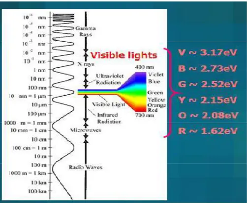
Visible light is coming under electromagnetic spectrum which have unlicensed bandwidth in range of THz shown in fig. 2. Whereas RF have GHz range
Fig. 1. Different LED
Data transmitted as binary codes i.e. when LED is off indicating binary 0 is transmitted; similarly when LED is on indicating binary 1 is transmitted.
Fig. 2. Electromagnetic spectrum
PLC has adapted version of modulation and channel estimation [1],[3],[4]. It could act as the backbone network for an indoor VLC system. In this data is send over existing power lines. Due to the VLC integrated PLC current infrastructure complexities are
further reduced. For supporting multiple services, including data transmission and navigation services BDM schemes are introduced [3],[9],[11]. Hence quality of service (QoS) and spectral efficiency is improved. This paper mainly discuss about the comparison between these approaches and to obtain the better performing one.
II.LITERATURESURVEY
CLASSICAL VLC BROADCASTING
Fig. 3. Structure of Classical VLC broadcasting
From the structure shown in fig. 3, Ethernet is connected to modem via network cable. Connecting modem through Ethernet provide faster and more reliable internet connection. This is far better than connecting wirelessly. Hence devices are connected to internet via communication cable. Devices can be computer, mobile phone, tablet etc., which act as receiver section. These devices have photo-detector section which may already present in it or can be incorporated in it (similar to a USB). Power line provided for driving the LED lamp. Perhaps this since LED is LOS; initially location of devices has to be located. For that in downlink, transmitters send secret keys to locations. Receivers only in certain location can be able to correctly track this secret key. Hence in uplink, devices use the received key for obtaining secret message and sends cipher text to control unit (CU). Control unit is the server. If the message transmitted obtained correctly then access is provided to that device. Ethernet provide data as packets or frames. Which contain sourceand destination address. Transmitted data were modulated in modem section. This is followed by conversion of data format for driving the LED.
Fig. 4. A receiver with three photodiodes in different orientations
Data which is converted to current signal were used for biasing followed by transmission of data wirelessly by LED. Si-photodiode receives optical current and converted to electrical signal proportional to it. They in turn passed to comparator where intensity adjustments being performed then to demodulator circuit.
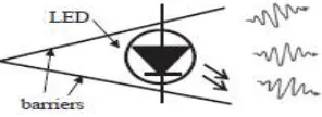
In demodulator, analog data were again converted to digital signal. This signal is passed to device for providing services. Performance of classical VLC broadcasting [4] can be increased further by putting LED in between barriers as in fig. 5 so that size and shape of the light spot can be controlled. Non-portable devices can have multiple amounts of photodiodes in different orientation. An example for this is given in fig. 4. This helps to capture signal from all direction. Even this arrangement create device complexity arises. And modulation used here is SSC-PSK modulation. Data rate reach less than 1GHz.
INTEGRATED PLC AND VLC BROADCASTING
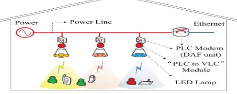
Integrated PLC and VLC [1] comes from the observation that power line which is used for driving the LED lamp can alone act as a backbone for VLC. This technique will save additional cables and easier to installed. Initially single carrier binary phase shift keying (SSC-BPSK) modulation were used which is then changed to orthogonal frequency division multiplexing (OFDM). OFDM [6] helps to combat the fading channel and to achieve better spectral efficiency. Generally the working can be say in simple words i.e. signal in power line is amplified and forwarded to the LED without decoding and all the LED lamps in one group transmit the same signal. Hence single frequency network (SFN) is created. A SFN is a broadcast network in which transmitters simultaneously send the same signal over the same frequency channel at the same time.Fig. 6 presents the diagram of indoor broadband broadcasting based on the integration of PLC and VLC. Initial step is common to classical VLC broadcasting i.e. location identification. After successful secret message transfer then only data transfer occur. From the Fig. 6, the structure has power line cable which is used for driving and transferring data to access point.Data from Ethernet is coupled by PLC modem. Where PLC modem is a combination of encoding and modulation unit with coupler as shown in Fig. 7.
Fig. 6. Structure of integrated PLC and VLC
From Fig. 7, the PLC modem is integrated with decoding and forwarding unit (DAF). DAF is present on each and every LED lamp to get the required data from the power line. While the “PLC to VLC” module in fig. 8, initially data is demodulated and decoded by the PLC transmission standard, and then encoded and modulated again with the VLC transmission protocol with the navigation data.
So that navigation and data transmission services could be simultaneously realized. “PLC to VLC” module is equipped to modulate the signal to the light.
Fig. 7. PLC modem
Hence the transmitted signal from different LED lamps could be different depending upon the request. These mixed signals were encoded and modulated again. Mixed signal is then added to the direct current (DC) bias of LED, for driving the LED lamp for both information and illumination.
Navigation data
Data
Fig. 8. PLC to VLC module
Driver Encoding
and modulation M
U X Decoding
and
Demodulation
Coupler Transmission data Encoding
In receiver section as illustrated in fig. 9, have avalanche photodiode (APD), where the data as light is captured. And they converted to electrical signal which is demodulated and decoded into digital form again for read out by devices. Above structure can be made less complex by deeply integrated PLC and VLC system. In that single modem is used and size of “PLC to VLC” module is reduced. Hence we obtain better signal coverage effective cost. OFDM modulation is used with TDM. Hence different time slot is provided for localization and navigation services.
Fig. 9. Receiver
INTEGRATED PLC AND VLC SYSTEM WITH BDM
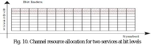
BDM technique is applied for multi-service [8],[3],[10] transmission of the integrated PLC and VLC system and the mechanism is more convenient than on using TDM scheme. In traditional strategy of channel resource allocation at symbol level, they have done it in the manner of time, frequency or time frequency division. Unlike that the BDM scheme supports multi-service crosses multiple symbols at the bit level. Multi-service transmission in the BDM scheme is achieved by bits carried by every N symbols are separated into multiple parts arbitrarily. And these each part creates a sub-channel and used for transmitting each service. For example, 256-QAM constellation mapping employed by every symbol for two-service transmission is considered.Across N symbols, the BDM scheme allocates certain amount of bits out of the total bits (8N) to each serviceand the number of possibilities
of allocating8Nbits to two services is 28N. Unlike TDM scheme channel resource allocation is significantly improved compared with the BDM scheme. One possible scheme of channel resource allocation is illustrated in fig. 10. When the BDM scheme is-employed, the constellation mapping for each symbol can be any different and high order constellation can be supported, which provides more flexibility and diversity.
Fig. 10. Channel resource allocation for two services at bit levels
As a result, effective bit allocation scheme in BDM scheme can be found to improve the system throughput. Actually, BDM outperforms the conventional TDM scheme in the system throughput, benefited from different error protection capacities of different bits within each high-order constellation symbol. In BDM, data transmission and navigation service, as global and local services, could be realized using BDM scheme.The navigation service is transmitted by the bits with higher index, which has the lower error protection level, as shown in fig. 10.A SFN [3] is a broadcast network where several transmitterssimultaneously send the same signal over the same frequency channel at same time. In our proposed system, a SFN is inherently formed for all the LED lamps connected to the same PLC modem, which transmit the same data for all the LED lamps connected to the power line. In this way, the problem that the devices roaming in the coverage area of the whole LED lamps have to frequently switch among the access points (i.e. LED lamps) can be solved, thus the complicated switching protocol would be avoided. However, as illustrated in fig. 11, there is a little difference in our SFN structure compared to the conventional one. The transmitted signal is not the same for all LED lamps, since thebits of navigation service are vary according to different LED lamps which lead to a novel SFN
APD Demodulation and
structure with the capacity to support both global and local services. The BDM scheme provides an interesting approach of supporting multiple services, i.e. global and local services simultaneously in a SFN [8].
Fig. 11. The SFN structure for BDM
To be specific, the bits of the global and the local services are dividing into two separate sub channel. Because the different bits carried by the embedded constellation have the different error protection levels, which cause the different capacities of different sub-channels. Meanwhile, the forward error correction schemes and interleaving depths for the global and local services can also be customized. Therefore, the proposed scheme can accommodate different requirements of QoS.
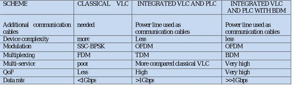
III. COMPARISON BETWEEN TECHNIQUES
From the above techniques of visible light communication better one is chosen based on the performance level. Data rate, modulation, signal strength, noise immunity [10], device complexity etc. were considered for identifying the better one. Hence on evaluating this integrated PLC and VLC system with BDM scheme has more performance capability compared to other structures. The overall transmission rateof multiple services subject to the differentiated minimum signal to noise ratio (SNR) required for successful receptions of BDM scheme Based on this comparison a table.(1) is given were the details are mentioned.TDM or FDM schemeallocates the symbols within a certain fraction of time or frequency resource to each service. However, the maximum overall transmission rate of multiple services obtained by TDM or FDM scheme is far away from that of ideal superposition coding [14]. Bit division multiplexing (BDM) scheme [14], which extends the multiplexing from symbol level to bit level, is applied to bring in an increment in multi-user channel capacity and improve the flexibility of channel resource allocation. The bits of different services are multiplexed in bit level.
For instance, the bits of transmission service are unique for all LED lamps as global service, and the bits of navigation service vary according to different LED lamps. Therefore, the BDM scheme could support the different services, e.g., data transmission and navigation services simultaneously, in the novel architecture of single frequency network (SFN).
SCHEME CLASSICAL VLC INTEGRATED VLC AND PLC INTEGRATED VLC AND PLC WITH BDM
Additional communication cables
needed Power line used as communication cables
Power line used as communication cables
Device complexity more Less less
Modulation SSC-BPSK OFDM OFDM
Multiplexing FDM TDM BDM
Multi-service poor More compared classical VLC Very high
QoP Less High Very high
Data rate <1Gbps >1Gbps >>1Gbps
IV. APPLICATION
LED lamps are widely available now. Since they are cheaper in rate, smaller in size, power consumption is less and maintains is easy, can be used for data transfer. For example, many cars have LED lamps, traffic sign boards, traffic lights and street lamps are using LED technology. So there are massive applications there. We can use this light for identifying the crowed area, accident warning etc. There are other useful applications are listed below,
Smart lighting
Under water communication
RF sensitive areas, Aerospace application
V. CONCLUSION
Visible light communication is a growing field. Since more number of LED is using now days its application will be vast. From the three techniques mentioned in this paper better performing one is BDM scheme. Since it has high data rate compared to others, multi-service can be effectively performed, Noise immunity is high and so on. Hence visible light can be used as an alternative to the conventional RF technology.
REFERENCES
[1] J. Song, W. Ding, F. Yang, H. Yang, B. Yu and H. Zhang,"An Indoor Broadband Broadcasting System Based on PLC and VLC," in IEEE
Transactions on Broadcasting, vol. 61,no.2,pp.299-308,June2015.
[2] S. W. Ho, W. G. Cowley, K. Nguyen and J. Duan, "An integrated wireless system using visible light," 2013 IEEE/CIC International Conference
on Communications in China (ICCC), Xi'an, 2013, pp. 61-67.
[3] J. Gao, F. Yang and W. Ding, "Novel Integrated power line and visible light communication system with bit division multiplexing," 2015
International Wireless Communications and Mobile Computing Conference (IWCMC), Dubrovnik, 2015, pp. 680-684.
[4] H. Ma, L. Lampe and S. Hranilovic, "Hybrid visible light and power line communication for indoor multiuser downlink," in IEEE/OSA Journal of
Optical Communications and Networking, vol. 9, no. 8, pp. 635-647, Aug. 2017.
[5] D. Karunatilaka, F. Zafar, V. Kalavally and R. Parthiban, "LED Based Indoor Visible Light Communications: State of the Art," in IEEE Communications Surveys & Tutorials, vol. 17, no. 3, pp. 1649-1678, third quarter 2015.
[6] M. S. A. Mossaad, S. Hranilovic and L. Lampe, "Visible Light Communications Using OFDM and Multiple LEDs," in IEEE Transactions on
Communications, vol. 63, no. 11, pp. 4304-4313, Nov. 2015.
[7] A. Mattsson, “Single frequency networks in DTV,” IEEE Trans. Broadcast., vol. 51, no. 4, pp. 413–422, Dec. 2005.
[8] H. Jin, K. Peng, and J. Song, “Backward compatible multiservice transmission over the dtmb system,” IEEE Trans. Broadcast., vol. 60, no. 3, pp. 499–510, Sep. 2014.
[9] H. Jin, K. Peng, and J. Song, “Bit division multiplexing for broadcasting,” IEEE Trans. Broadcast., vol. 59, no. 3, pp. 539–547, Sep. 2013. [10] P. Bergmans, “A simple converse for broadcast channels with additive white gaussian noise,” IEEE Trans. Inf. Theory, vol. 20, no. 2, pp. 279– 280, Mar. 1974.
[11] J. Song, H. Jin, and K. Peng, “Approaching capacity region for two-user GBC with bit division multiplexing,” to be published in IEEE Trans. Veh.Tech.
[12] F. Adachi and E. Kudoh, “New direction of broadband wireless technology,” Wireless Commun. Mobile Commun., vol. 7, no. 8,
[13] Y. Wu, S. Hirakawa, U. H. Reimers, and J. Whitaker, “Overview of digital television development worldwide,” Proc. IEEE, vol. 94, no. 1, pp. 8–21, Jan. 2006.