Division V
Integrity of pressure vessel lower head in case of corium relocation:
identification of loads and failure modes
R. Lo Frano1, D. Aquaro2, A. Facchini3, D. Del Serra4, N. Zaccari5
1 Assistant Professor, Mechanical Engineering and Nuclear Power Plant, University of Pisa, Italy 2
Full Professor, Mechanical Engineering and Nuclear Power Plant, University of Pisa, Italy
3 PhD Student, Nuclear Engineering, Seoul National University, Korea 4
PhD, Nuclear Engineering, Seoul National University, Korea
5 Research & Development, ENEL Spa, Rome, Italy
ABSTRACT
Fukushima Daiichi accident emphasized that the complex phenomenology of In Vessel Corium Retention (IVCR) and Ex Vessel Corium Cooling/stabilization (EVCC) strategies has to have a highest priority in the programs of R&D.
The IVCR foresees the flooding of the reactor cavity before the relocation of the corium in the pressure vessel lower head occurs. The cooling of the corium is performed by means natural circulation of the water in inside the reactor cavity in regimen of nucleate boiling. The maximum heat flux is limited by the critical heat flux which determines the passage from the nucleate to the film boiling. Another limit on the maximum heat flux is imposed by the maximum heat flux by conduction through the lower head material. This limit is defined by the minimum thickness which assures the structural integrity of the vessel. A common assumption is that the corium relocation occurs in a depressurized primary system. Nevertheless a minimum value of pressure cannot be excluded for the presence of the evaporating water or for localized steam explosions. The lower head is loaded by the hydrostatic pressure caused by the corium weight. Moreover the thermal gradient in the thickness produces bending thermal stresses.
This paper considers potential ranges of loads and identifies the appropriate failure modes and the correspondent material characteristics.
A numerical analysis is also performed by a FEM code considering a degraded configuration determined by the interaction with the corium.
1 INTRODUCTION
The severe accident in a LWR assumes the occurrence of a meltdown of the core, whose corium can breach the safety barriers (in a short time if exothermic reactions occur) in absence of coolability, with consequently release of radioactivity to the environment. Therefore, the prevention of the failure of the bottom head of the vessel, first, and of the containment and/or the basemat melt-through, later, is felt of meaningful importance for the severe accident management (SAM).
It is commonly recognized that the IVMR strategy achieved by enhancing the external reactor vessel cooling and/or in-vessel flooding (known as In Vessel Corium Retention (IVCR) and Ex Vessel Corium Cooling/stabilization (EVCC) [1÷3]) is one of the most effective measures to prevent the progression of severe accidents at water-cooled reactors. Several operating nuclear power reactors (e.g. VVER-440) or new ones (e.g. AP1000, ACP 100) use IVMR strategy and have dedicated systems [4÷7]. A lot of R&D [8÷12] has been done and are still on-going to develop IVMR strategy and technologies at national, regional and international level oriented at increasing the safety margin, and the Fukushima Daiichi accident revitalized it.
Indeed, this accident pointed out the need of a substantially reduction of the heat flux from the metal layer on the vessel in order to preserve a margin to the CHF (additional time grace to manage emergency).
melt-24th Conference on Structural Mechanics in Reactor Technology BEXCO, Busan, Korea - August 20-25, 2017 Division V
pool composition, configuration to investigate, heat transfer processes during the melt progression, how the melt relocates, etc. [3-5].
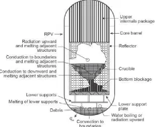
Fig. 1: Core meltdown and melt-relocation (to the bottom head) scenarios as during TMI-2 accident: material configuration and heat transfer processes at an intermediate state of melt progression, after initial major relocation and before final steady state [4].
This paper deals with the investigation of a new IVCR approach, based on an internal core catcher made of alumina.
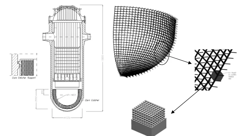
In this study we will analyze loads, failure modes, and material properties characterizing it during the relocation phase. This new alumina made internal core-catcher concept, developed at the Department of Civil and Industrial Engineering (DICI) of the University of Pisa (Italy), consists of the alumina pebble-bed that are positioned within alumina boxes, as shown in Fig. 2.
The selection of the alumina is because of its high refractoriness and capability to accommodate thermal expansion without high thermal stresses. The boxes are assembled like bricks of masonry, supported by means of a CMC (SiC-SiC) framework. The internal and external liners of core catcher are made of high alloy steel [2].
To the aim of this study we will analyse the feasibility of the envisaged solution through:
• Analytical approach: a parametric analysis on a simplified model was developed solving the Fourier’s equation to analyze time-constant heat flux effect.
Fig. 2: Overview of the proposed internal core catcher (left figure) and of the frame structure made of SiC-SiC ceramic matrix composite with box filled by alumina pebble bed (right figure) for a RPV of 1000 MW PWR.
2 PRELIMINARY ANALYTICAL ANALYSIS
The idea of an internal core catcher (ICC) dates back to Theofanous et. al. [1÷5], who first formulates the idea of the retention of core melt inside the vessel (as a severe accident management (SAM) strategy) as safety upgrade of the VVER-440 plant, Loviisa, in Finland [1]. In 1995, Finnish Authority for the plant approved this SAM [6]. By adopting the ICC ex-vessel events will be indeed minimised/avoided (DCH, steam explosions…)[3-9].
The internal core catcher approach is based on the successful coolability of the core melt (temperature higher than 2000°C) at the bottom head, allowing the stabilization of the severe accident. The instauration of heat transfer processes will ensure that at least the bottom layers of the RPV wall thickness are not undergoing “heat flux focusing effects” [6-7] and keep unaltered structural properties.
The ICC has to be properly designed in order to account for the thermal effects (and material degradation occurring during the core melting and relocation).
It is understood from the past research that molten pools separate into 2 layers (i.e. lower oxidic layer and upper liquid metal layer) or 3 layers (heavy metal, oxidic and light metal layers), and there forms an oxidic crust between the oxidic and light metal pools. ICC issues are due to the heat-up of vessel thickness from the inside because of the metal melt layer, riding on the top of the crusted upper boundary of the oxidic melt pool, and to the heat removal capacity.
In consideration of that and of Theofanous theory, we proposed an ICC concept characterised by the inner surface of the RPV bottom head coated with an internal layer made of alumina pebbles bed.
In this way, we will increase the overall thickness of bottom head facing heat flux and delay the heating-up of RPV wall profiting of the lower thermal conductivity of alumina [8]. The aim is to avoid the “boiling crisis” of the bottom head.
The adoption of this ceramic layer, resting on the inner bottom head, will increase the area of the metal layer in touch with the vessel so to keep the imposed heat flux below ~1.5MW/m2 (corresponding to 1.3 MW/m2 maximum thermal load for a 1000 MWe PWR). This value was the one measured in ULPU-2000 experimental facility without any special shaping of the flow.
24th Conference on Structural Mechanics in Reactor Technology BEXCO, Busan, Korea - August 20-25, 2017 Division V
• Primary system depressurized.
• Lower head fully submerged in cavity water before that core debris reaches the lower head.
• Water level in the cavity would be maintained indefinitely.
In the setting up of the methodology to determine the suitable alumina thickness, we first start analysing a simple static model, solving the heat transfer equation, in spherical coordinates, by assuming a constant thermal conductivity (k) and q’’’= 0. No chemical reactions were included in that assessment.
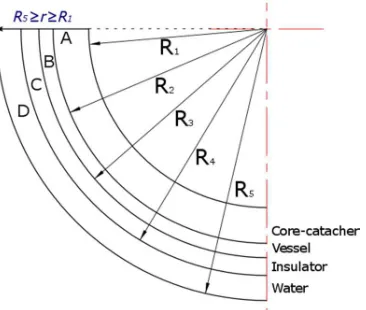
In Fig. 3 is represented the RPV bottom head axial section along which Fourier problem is solved; from the inner to the outer the thickness is made of the internal core catcher, the steel, the outer insulator and the water. This steady state problem in one dimensional system, exhibiting azimuthal and poloidal symmetry, is only dependent on the radius, and is solved by direct integration of the Laplace equation:
r C C r
T 2
1 )
( = + (1)
For the water (whose presence is because of LBLOCA), layer D in the scheme of Fig. 3, the thermodynamics conditions are: atmospheric pressure and an unknown temperature distribution that tends to a cavity-wall fixed temperature [1, 3, 4]. The thermal insulation (layer C in Fig. 3) has the same low thermal conductivity (0.15 W/m/K) and thickness (0.25 m), of the real one in nuclear reactor [5]. The boundary conditions are respectively the melt temperature and the water temperature (= 40 °C).
Fig. 3: Analytical model with thermal insulator (instead of adiabatic boundary condition). The boundary conditions are T(R1)=Tcorium and T(R5)=Twater.
Table 1: Geometrical and material properties of the simplified model.
Region Radius r
[m]
Thickness t [m]
Thermal conductivity k [W/m/K]
Core-catcher [6, 7] 2.50÷3.00 0.5 0.50
Vessel 3.00÷3.20 0.2 18.00
Insulator [5] 3.20÷3.45/3.50 0.25/0.30 0.15
Water 3.45/3.50÷3.80 0.30/0.35 0.60
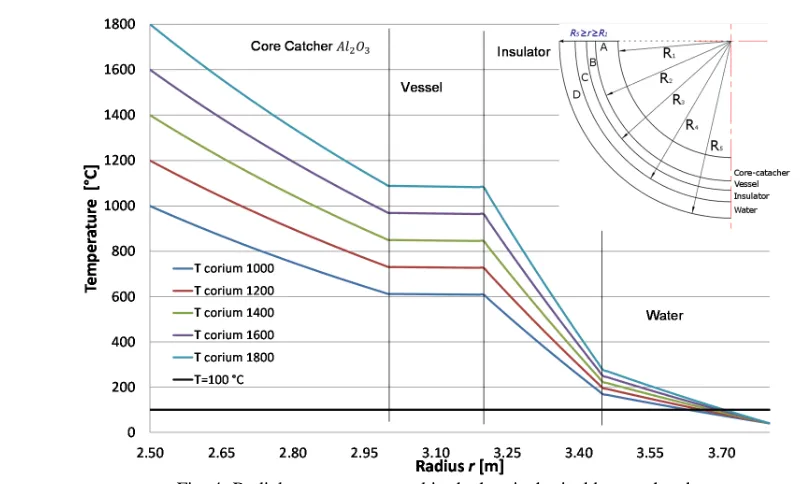
Fig. 4: Radial temperature trend in the hemispherical bottom head.
From results represented in the previous figure 3, it was observed that the water temperature in contact with thermal insulator is higher than 100 °C and it should not be [1- 4].
A parametric study was carried out in order to identify the right R5 (below 0.15 m) for which TD (R4) is less than 100 °C (at t∞). In this case, the solution of Laplace equation is consistent with the problem and
the static solution can be used directly without analysing the transient. A second parametric analysis was performed varying the in core-catcher thickness and keeping R5=3.55 m.
Fig. 5 shows the reduction of average vessel temperature (diamond shape) and of the insulator-water interface temperature (squared shape) with variation of the alumina thickness from 60 cm down to 10 cm.
Fig. 5: Temperature trend for different core-catcher thickness.
In the case the Theofanous’ hypotheses are assumed valid and the reference ones, we could iterate the previous calculation in the same geometrical domain expect for the water content. This result in a modification of outer boundary condition that becomes: T(R4) = Twater=100 °C. The loss of heat along the
wall thickness due to the only conduction in this case is plotted inside Fig. 6:
0 200 400 600 800 1000
0 0,2 0,4 0,6 0,8
T
e
m
p
e
ra
tu
re
[
°
C
]
Alumina thickness [m]
24th Conference on Structural Mechanics in Reactor Technology BEXCO, Busan, Korea - August 20-25, 2017 Division V
Fig. 6: Radial temperature variation in the hemispherical bottom head for T(R4) = Twater = 100°C.
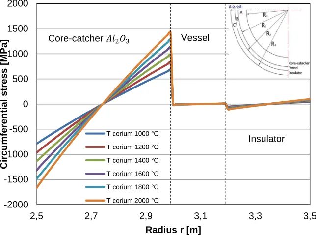
Then, the circumferential thermal stress, calculated analytically for different temperature, highlighted that the thermal stresses are relevant inside the core-catcher and change with Tcorium; inside the vessel and
within the thermal insulator the stress state is zero, as shown in Fig. 7.
Fig. 7: Circumferential stress behaviour, in the A, B and C layers, as function of the corium temperature.
The presence of core-catcher allows the vessel, during transient and steady-state, to undergo a lower temperature than the same condition without. Fig. 8 shows clearly the positive effects due to the core-catcher. 0 400 800 1200 1600 2000
2,5 2,7 2,9 3,1 3,3 3,5
C o ri u m T e m p e ra tu re [ ° C ]
Radius r [m]
T corium 1000°C T corium 1200 °C T corium 1400 °C T corium 1600 °C T corium 1800 °C T corium 2000 °C
Core-catcher Vessel
Insulator -2000 -1500 -1000 -500 0 500 1000 1500 2000
2,5 2,7 2,9 3,1 3,3 3,5
C ir c u m fe re n ti a l s tr e s s [ M P a ]
Radius r [m]
T corium 1000 °C T corium 1200 °C T corium 1400 °C T corium 1600 °C T corium 1800 °C T corium 2000 °C
Core-catcher Vessel
Fig. 8: difference between the vessel average temperature with and without the core-catcher.
3 COMPUTATIONAL ANALYSIS
Numerical approach, herein following presented, is used in order to investigate the core catcher at the final state of corium relocation. Fig. 9 shows the bottom head scheme together with heat transfer modes that dominate the evolution of accident.
Fig. 9: Heat transfer mechanism during severe accident.
To determine the heat flux we solved first the global energy balance inside corium, whose equation is:
up dn
o
o
V
S
S
Q
′′′
=
q
dn′′
+
q
up′′
(2)0 500 1000 1500 2000 2500
0 500 1000 1500 2000 2500
V
e
s
s
e
l
a
v
e
ra
g
e
t
e
m
p
e
ra
tu
re
[
°
C
]
Corium temperature [°C]
No core-catcher With core-catcher
qup,h qup,h q
24th Conference on Structural Mechanics in Reactor Technology BEXCO, Busan, Korea - August 20-25, 2017 Division V
The subscript o means corium oxide, dn downward heat flux (onto the core-catcher) and up upward heat flux (at light metallic layer). is the volumetric heat source into the oxidic derived from decay heat power, that is calculated as function of the Rayleigh’s number and Prandtl’s number, like [10]:
k
Q
H
g
oνα
β
′′′
=
5 0Ra
(corium oxide);k H g
να
β
3 mlRa = ∆ (metallic layer) (3)
By substituting the effective downward and upward thermal resistances (Reff,dn and Reff,up), determined
through the thermal analogy at each boundary edges, in the above equation (2), the downward and upward heat flux heat may be calculated as:
)
1
(
S
V
Q
, , dn o o dn up up eff dn eff dnS
S
R
R
q
+
′′′
=
′′
and up o oS
V
Q
dn dn upS
q
q
′′
=
′′′
−
′′
(4)The resistances are calculated by considering the following temperatures and coefficients [12÷16] and the parameter provided in Table 2.
Tml,bulk=2954 K Tvess=Tcavity=400 K Tcc,dn=410 K σ=5.67037 10-8 W/m2/K4
Tml,ub=2800 K Po=12 MW Qo’’’= Po/Vo ε=0.4 n=0.5
Table 2: data for metallic layer and oxidic corium pool [12-16].
Density [kg/m3] cp [J/kg/K] k [W/m/K] β [K-1] Volume [m3] μ [Pa s]
Corium 8740 485 5.3 1.10 10-4 14.25 4.1 10-3
Metallic layer 7020 835 32.0 1.05 10-4 8.50 5.3 10-3
Core-catcher 3970 1560 0.25 8.40 10-6 23.80 /
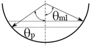
Finally, the downward and upward heat fluxes, to use in the FEM model (Fig. 10) resulted 962 W/m2
and 723440 W/m2 respectively in the corium oxide and 852 and 637443 W/m2K inside the metallic layer.
Fig. 10: model for the estimation of thermal flux in the presented model: θml=78° and θp=67°.
3.1 RESULTS AND COMMENTS
The numerical analyses were carried out by means of FEM code MSC©Marc. We simulated the thermal conductivity of the pebble bed box, under the maximum pressure and temperature of the corium, by assuming:
- adiabatic condition on the core catcher external surface (no radiation flux surface); - corium cooled only from the top surface by passive cooling systems;
- pressure on top surface Pts =0.19 MPa;
- temperature on top and bottom surface: Tts= 1273 K and Tbs = 1000 K.
Fig. 11: FEM model 3D sphere sector of core catcher [3]
Thermo-mechanical results, for 500 W/m2 maximum heat flux at core catcher internal surface, show that
a 500 mm core catcher thickness could withstand the accident conditions until 39 days (Fig. 12).
a) b)
Fig. 12: a) Temperature trend in the core catcher and b) temperature distribution in a sector [9].
It was also observed that about 260 mm of the core catcher melt, despite integrity of the bottom head is not impaired if coolability is assured.
4 CONCLUSION
In this paper, we presented an original design of a core catcher made of alumina pebbles bed. Analytical and numerical approaches are presented in order to highlight the positive effects provided by the insertion of batch of ceramic multi-layered pebble (encased in CMC boxes).
FEM simulations of the core catcher behavior under severe loading conditions highlighted: - a time grace of 39 days (500 W/m2 on the internal surface) if corium cooling is guaranteed; - the metallic (external) liner reaches 1350 K at 3.6x10⁶ sec from the beginning of transient.
- half thickness of the core catcher is melt.
Results show also that the core catcher, under the most conservative scenario, could resist indefinitely if coolability from the upper surface is guaranteed.
REFERENCES
24th Conference on Structural Mechanics in Reactor Technology BEXCO, Busan, Korea - August 20-25, 2017 Division V
[2] O. Kymäläinen, H. Tuomisto, T. G. Theofanous, In-vessel retention of corium at Loviisa, Nuclear engineering and design 169 109-130, 1997.
[3] D. Aquaro and N. Zaccari, Mitigation of a core Meltdown scenario by means of a core catcher located inside the reactor pressure vessel, 12th ICONE, Arlington 2004, USA.
[4] T.G. Theofanous, C. Liu, S. Additon, S. Angelini, O. Kyma¨la¨inen, T. Salmassi, In-Vessel Coolability and Retention of a Core Melt, DOE/ID-10460, vols. 1 and 2, October 1996.
[5] T. G. Theofanous, C. Liu, S. Additon, S. Angelini, O. Kymäläinen, T. Salmassi, In-vessel coolability and retention of core melt, Nuclear engineering and design 169 1-48, 1997.
[6] Nuclear Safety in Light Water Reactors, Severe Accident Phenomenology, Academic Press, Elsevier, chapter 6, 519-588, 2012.
[7] R. Kolbe and E. Gahan, Survey of Insulation Used in Nuclear Power Plants and the Potential for Debris Generation, NUREG/CR 2403 Supplement n. 1, SAND82-0927, May 1982.
[8] R. Lo Frano, D. Aquaro, S. Pupeschi, M. Moscardini, Thermo-mechanical test rig for experimental evaluation of thermal conductivity of ceramic pebble beds, Fusion engineering and design 89 1309-1313, 2014.
[9] D. Aquaro, R. Lo Frano, N. Zaccari, Original core catcher design in order to manage the core meltdown severe accident with the in-vessel retention strategy, IAEA technical meeting Shanghai 17-21 October 2016.
[10] D. Zhu, Q. Xiang, M. Zhang, C. Deng, J. Deng G. Jiang, H. Yu, Evaluation of in-vessel corium retention margin for small modular reactor ACP100, Annals of Nuclear Energy 94 684-690, 2016. [11] R.-J Park., J. R. Lee, K. S. Ha, H. Y. Kim, Evaluation of in-vessel corium retention through external
reactor vessel cooling for small integral reactor, Nuclear Engineering and Design 262 571-578, 2013. [12] P. Tusheva, E. Altstadt, H.-G. Willschütz, E. Fridman, F.-P. Weiß, Investigations on in-vessel melt retention by external cooling for a generic VVER-1000 reactor, Annals of Nuclear Energy 75 249-260, 2015.
[13] F. Mayinger, M. Jahn, H. H. Reineke, V. Steinberner, Examination of thermal hydraulic processes and heat transfer in a core melt, BMFT RS 48/1, Institut fur Verfahrenstechnik der T. U., Hanover, FRG, 1976.
[14] T.G. Theofanous, M. Maguire, S. Angelini, T. Salamassi, The first results from the ACOPO experiment, Nuclear Engineering and Design 169 49-57, 1997.
[15] U. Steinberner, H. Reineke, Turbulent buoyancy convection heat transfer with internal heat source, Proceedings of 6th International Heat transfer Conference, Toronto August 1978.
[16] S. Globe and D. Dropkin, Natural convection heat transfer in liquids confined by two horizontal plates and heated from below, Journal of heat transfer 81 24, 1959.
[17] S. W. Churchill and H. H. S. Chu, Correlating equations for laminar and turbulent free convection from a vertical plate, Journal of heat transfer 18, 1323-1329, 1975.

![Fig. 11: FEM model 3D sphere sector of core catcher [3]](https://thumb-us.123doks.com/thumbv2/123dok_us/1522346.1186596/9.595.75.522.340.488/fig-fem-model-d-sphere-sector-core-catcher.webp)
