Abstract
BOONMA, APICHART. Haptic-Based Sharp Edge Retaining and Gap Bridging Algorithms for Computer Aided Design (CAD) and Reverse Engineering (RE). (Under the direction of Dr. Yuan-Shin Lee).
The objective of this paper is to develop a computational and haptic interface
technique to improve the repair of non-watertight virtual models through the enhancement of
hole filling, sharp edge retaining and gap bridging strategies. In Reverse Engineering (RE), a
virtual model is created from point cloud data using surface fitting or triangulation
techniques. Point cloud or three dimensional position data is usually acquired by laser
scanning a physical object. Obtaining data that well characterizes the part surface is quite
difficult. Defective point cloud that is caused by loss or non-uniform distribution of scanning
points might lessen the quality of the resulting virtual model and these defects usually appear
as holes or gaps on the constructed triangulate facet surfaces. Such model is usually called a
non-watertight model.
Watertight triangulate facet model is very important for many applications, such as
reverse engineering (RE), computer-aided design (CAD), rapid prototyping (RP) and NC
machining. How to fix and repair the non-watertight triangulate facet models with defects is
vital for computer aided design (CAD) and reverse engineering (RE).
This thesis focuses primarily on developing a technique to repair holes and gaps on
the triangulate facet models. Haptic-based sharp edge retaining and gap bridging algorithms
are presented in this paper. Our haptic-based hole filling algorithm can be used to selectively
repair only the defective holes chosen by the user. The proposed haptic-based sharp edge
To seal the gap between two surfaces, a haptic-based gap bridging algorithm is proposed.
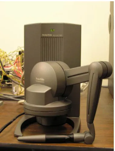
The proposed algorithms were implemented with a 6-DOF (degree of freedom)
PHANTOM Desktop™ haptic device at our research lab. The haptic interface device is used
to provide force and torque feed back to the user and to provide accessibility to the surface of
the input model. The user can feel the surface of the model, select the hole that needs to be
repaired, specify parameters in order to construct sharp edge, and bridge the gap that appears
in the surface model. All the works are performed in real time basis. The implementation
results show that our techniques can be used to repair holes and gaps in a non-watertight
model and transform the model into a watertight one. The proposed techniques can be used in
Haptic-Based Sharp Edge Retaining and Gap Bridging
Algorithms for Computer Aided Design (CAD)
and Reverse Engineering (RE)
By
Apichart Boonma
A thesis submitted to the Graduate Faculty of North Carolina State University
in partial fulfillment of the requirements for the Degree of
Master of Science
Industrial Engineering
Raleigh 2006
Approved By:
_________________________ Dr. Yuan-Shin Lee Chair of Advisory Committee
Biography
Acknowledgements
I would like to express my deep appreciation and gratitude to my advisor, Dr. Yuan-Shin Lee for his patience, suggestion and encouragement during my academic and research work at North Carolina State University. Without his guidance and continuous support, I would never have finished my study. I would like to thank Dr. Ezat T. Sanii and Dr. Stephen D. Roberts for their support and serving in my Master Thesis Committee.
I highly appreciate and would like to thank my research group members: Dr. Yongfu Ren, Dr. Susana K. Laiyuen, Shiyong Lin, Deyao Ren, Yingjie Li, Ronald L. Aman, Plawut Wongwiwat and Eui Seok Kim for their valuable discussions and suggestions.
I would also like to thank my friends: Pueng, Lena, Ann, Kaew, Pom and May for their discussions, support and encouragement.
Table of Contents
Page
List of Figures ………... vii
1. Introduction ……… 1
1.1Motivation ……… 1
1.2Research Objectives ……….. 6
1.3Thesis Organization ……….. 7
2. Literature Review ………. 8
2.1Virtual Model Reconstruction ……… 8
2.2Hole and Gap Filling, Subdivision and Surface Smoothing …………... 9
2.3Sharp Edge Retaining ……….. 13
2.4Haptic Interface Device ………... 14
2.5Summary ………... 17
3. Haptic-Based Hole Filling Algorithm ……… … 18
3.1Introduction ……….. 18
3.2Haptic Interface System for Repairing Surface Models ………. 19
3.3Hole Search Algorithm ………. 21
3.4Haptic-Based Hole Filling Algorithm ……… 24
3.4.1 Creating Reference Plane ……….. 25
3.4.2 Closing Predefined Angle .………. 26
3.4.3 Triangulation Over Hole Area……… 28
3.4.4 Subdivision ……… 30
4. Haptic-Based Sharp Edge Retaining and Gap Bridging Algorithm ……… 35
4.1Introduction ……… 35
4.2Haptic-Based Sharp Edge Retaining Algorithm ………... 36
4.2.1Constructing Hermite Curve and Guiding Surface ………. 38
4.2.2Vertices Snapping for re-aligning triangle vertices……….. 42
4.2.3Surface Modification Using Haptic Interface Device ………. 44
4.2.4Surface Smoothing ……….. 45
4.3Haptic-Based Gap Bridging Algorithm ………. 48
4.3.1Manual Gap Bridging Algorithm ………. 48
4.3.2Semi-automatic Gap Bridging Algorithm ………... 51
4.4Summary ……….. 53
5. Examples and Results ………. 54
5.1Examples of Models with Sharp Edge Resulted From Haptic-Based Hole Filling and Sharp Edge Retaining Algorithm ……… 54
5.2Examples of Models Resulted from Haptic-Based Gap Bridging Algorithm 62
5.3Summary ………. 68
6. Conclusions and Future Researches ……… 69
6.1Conclusions ………... 69
6.2Future Researches ……… 70
List of Figures
Page
Figure 1.1 Point cloud data of a mobile phone ………...………. 2
Figure 1.2 Example model with defects ……….. 3
Figure 1.3 Example model with some holes left intentionally ……… 4
Figure 1.4 Example of a geometrical part ……… 5
Figure 1.5 Example of a free form model ……… 5
Figure 2.1 Gaps repair ……….. 10
Figure 2.2 A sphere model with defective holes ……… 11
Figure 2.3 The repaired sphere model ……… 12
Figure 2.4 Examples of haptic interface devices ……… 15
Figure 2.5 PHANTOM Desktop™ haptic interface device ……… 16
Figure 3.1 Example of a model with a defective hole locating at sharp edge ……… 19
Figure 3.2 Lab setup haptic interface device ……….. 20
Figure 3.3 Boundary edges ……….. 21
Figure 3.4 Example of hole without coincident point……..……… 22
Figure 3.5 Example of hole with coincident point ………..……… 23
Figure 3.6 Flow chart of haptic-based hole filling algorithm ………..……… 24
Figure 3.7 Hole normal vector ………. 25
Figure 3.8 Intersection of new triangle and hole boundary edge ………. 27
Figure 3.9 No intersection of new triangle and hole boundary edge ……… 27
Figure 3.10 No intersection of new triangle and hole boundary edge (triangulation).. 29
Figure 3.11 The hole filled by Triangulation ……….... 30
Figure 3.12 Splitting triangle ……… 33
Figure 3.13 Edge relaxing method ……… 33
Figure 4.2 Example of four points for constructing Hermite curve ………. 39
Figure 4.3 Hermite curve created from four selected points ……….. 40
Figure 4.4 Guiding surface created from Hermite curve ……….... 41
Figure 4.5 The guiding surface in the mouse model ……….. 41
Figure 4.6 Vertex snapping ………. 43
Figure 4.7 Result of our vertices snapping algorithm in the mouse model….…… 43
Figure 4.8. Manual gap bridging algorithm…..……… 49
Figure 4.9. Illustration of Manual Gap Bridging ………. 50
Figure 4.10 Semi-automatic gap bridging algorithm ……… 52
Figure 4.11 Illustration of Semi-automatic Gap Bridging………. 52
Figure 5.1. General concept of the proposed haptic-based hole filling and sharp edge retaining algorithm……… 56
Figure 5.2 Lab setup haptic interface device ……….. 57
Figure 5.3 The mouse model with a defective hole ………. 58
Figure 5.4 The mouse model with a defective hole after hole filled……… 58
Figure 5.5 The guiding surface and the repaired surface being pushed down………. 59
Figure 5.6 The resulted model after sharp edge retained……… ……… 59
Figure 5.7. A foot model with a defective hole at the toe area……..……… 60
Figure 5.8. A foot model with the defective hole repaired……… 61
Figure 5.9. The visual comparison between the original and the repaired model……. 61
Figure 5.10 The general concept of the proposed haptic-based gap bridging algorithm……… 63
Figure 5.11 A cow model with a defective gap ……… 64
Figure 5.12 Repaired cow model using manual gap bridging ……….. 65
Figure 5.13 Repaired cow model using semi-automatic gap bridging ………. 65
Figure 5.14 S-model with holes and gaps ……… 66
Chapter 1
Introduction
1.1
Motivation
“If we can create digital duplicate of our world as easily as we can take a picture of
what we see, the biggest breakthrough of the 21st century will be in manufacturing”
[Ping Fu, president and CEO of Raindrop Geomagic]
Reverse engineering (RE) is an approach consisting of series of processes, e.g. data capturing, preprocessing, surface fitting and CAD model generation, intended to create a
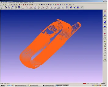
virtual object model of a physical part. It has been widely used in several areas such as design of product where the drawing and CAD data of the product are unavailable, inspection and quality control (to compare the CAD model with its physical object), production of CAD data for highly complicated part, observation and investigation of accident or crime scene, and etc. In the past few decades, various researches have been done in order to effectively and efficiently generate the virtual model that best approximates its prototype out of a set of data. This data, so called scattered, unorganized point or point cloud, describes surface of an object in the form of x, y and z coordinates and is usually obtained by laser scanning the physical part. An example of a point cloud can be found in Figure 1.1.
Figure 1.1 Point cloud data of a mobile phone.
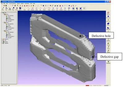
In reverse engineering (RE), although data acquisition is critical, the biggest challenge is the segmentation and surface fitting, which is the process of generating a surface that best describes a set of scanned point data [Varady 1997]. Surface fitting is also called object reconstruction due to its function to re-create surfaces of an object. Why is object reconstruction so important? It is because the process itself is usually difficult to achieve since there are several factors involved. These factors might cause surface fitting process to render incorrect surfaces, which most likely appear as defective holes and gaps as shown in Figure 1.2. The factors causing incorrect rendering might result from the laser scanning process, shiny surface of the physical parts, parts complexity (undercuts),
algorithm does exist today. To get around the problems, researchers proposed post processing techniques that are able to repair and turn a non-watertight model into the watertight one. These processes may consist of hole filling, triangle subdivision, surface smoothing and etc.
Defective hole
Defective gap
Figure 1.2 An example model with defects
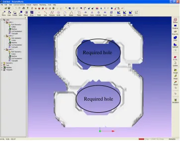
In hole repair process, holes appearing in a model could be classified into 2 major
categories; (1) functional holes, as shown in Figure 1.3, that are required to remain in the
model to perform some design functions, (2) defective holes that must be repaired. Hole
filling algorithm should be able to selectively repair only the defective holes. This
requirement is difficult to achieve automatically since the algorithm may not be able to
should be applied to help selecting a target hole, then the hole filling algorithm repair the
hole in automatic fashion.
Required hole Required hole
Figure 1.3 An example model with some holes left intentionally.
Moreover, if a repaired surface (the surface that is created in order to fit and eliminate
a selected hole) is required to represent sharp edge, the repairing algorithms should be
able to extract information from hole boundary and create such feature onto the repaired
surface. Some researches presented sharp edge retaining algorithm that could be only
applied to geometric parts (e.g. industrial parts), where two or more considered surfaces
shown in Figure 1.4. To the best of our knowledge, there is no existing algorithm that is
able to handle the cases where the normal vectors of the surfaces at sharp edge are not
much different, such as the free-form object shown in Fig 1.5.
In this paper, we propose haptic-based hole filling and sharp edge retaining algorithm
to repair the defective holes and generate sharp edges on complex surface models.
Sharp edge
Figure 1.4 A geometrical part whose triangular patches near sharp edge have very different surface normal vectors.
Sharp edge
1.2
Research Objectives
The objective of this paper is to investigate and develop computational and haptic
interface techniques to retain sharp edges, fill holes and bridge gaps in incomplete models. Our study aims to provide a tool for holes and gaps repair and sharp edge retaining using computational geometry and haptic interface. Some major research tasks are focused in this paper:
z Haptic-based Hole Filling Algorithm. This haptic-based algorithm provides
choices for users to selectively repair defective holes in incomplete surface model. The algorithm, except at the stage of selecting to-be-filled hole, works automatically.
z Haptic-based Sharp Edge Retaining Algorithm. This haptic-based algorithm
provides a tool for creating sharp edge over reconstructed meshes in order to
retain original shape of the model. It is performed in semi-automatic fashion.
z Haptic-based Gap Bridging Algorithm. This approach uses haptic interface
device to seal gaps between two surfaces. It can be classified into two sub-methods consisting of manual gap bridging and semi-automatic gap bridging. Manual gap bridging is a method that users control haptic interface device to gradually stitch the gap, while semi-automatic one is integration between the manual method and hole filling algorithm.
Haptic-based hole filling approach has some advantages over the conventional hole filling algorithm in that, it allows users to selectively fill only the defective holes. The proposed haptic-based sharp edge retaining algorithm helps creating sharp edge based on
1.3
Thesis Organization
The remainders of this thesis are organized as follows:
Chapter 2 presents a literature review on related research issues including object reconstruction, hole filling, subdivision, sharp edge retaining, surface smoothing, gaps bridging and haptic interface device.
Chapter 3 describes the proposed haptic-based hole filling algorithm for repairing defective holes.
Chapter 4 introduces the proposed sharp edge retaining and gap bridging algorithm for repairing incomplete surface models with defective holes around sharp edge, and gaps between two surfaces.
Chapter 5 shows illustrative examples and results of the proposed computational techniques and algorithms.
Chapter 2
Literature Review
In this chapter, we review the previous researches in 3D virtual model reconstruction algorithm which is, as described by its name, used to create surfaces representing an object from point cloud data. The recent researches on hole filling, triangle subdivision and surface smoothing algorithm are firstly discussed. Previous researches on sharp edge retaining algorithm is discussed next. And lastly, we end this chapter with review of
haptic interface device. These issues will be discussed further in the following chapters.
2.1
Virtual Model Reconstruction
A number of researchers have worked on modeling 3D virtual object from point cloud data. The developed object is usually illustrated in the form of triangular meshes. More information on recent researches can be found in [Mencl 1998] and [Bernaradini 1999]. Virtual object reconstruction algorithms can be classified into three major categories [Lin 2004] including sculpting-based, contour tracing and region growing approaches.
The sculpting-based approach includes alpha-shape [Guo 1997], γ - graph [Veltkamp
1995], β - skeleton [Kirkpatrick 1985], crust algorithm [Amenta 1998, 1999] and
umbrella filter algorithm [Adamy 1999]. This technique builds surface of an object by first decomposing the space into cells using Delaunay tetrahedrization/Delaunay triangulation and then eliminating the cells that do not meet its criteria. Finally, triangulation is used to create triangular patches representing surface of the object. The approach is quite robust but it could suffer from computational difficulty and expensiveness, especially in the early step where structure of the space is set up.
approximation techniques, which might not accurately describe surface characterizations. Therefore, in some cases where accuracy is highly important e.g. in industrial product design or quality control purpose, contour tracing-based reconstruction might not be preferable.
The last category, region growing approach, begins by finding a starting triangle called seed triangle. Then, new triangles are added to each edge of the seed and newly created triangular patches. The process is continuously repeated until no point left behind and every point belongs to at least one triangle. The examples of region growing approach include ball point algorithm (BPA) [Bernardini 1999], [Huang 2002] and IPD algorithm
[Lin 2004]. This method usually has a specific user-defined criterion for searching and creating new triangle. Thus, if the input point cloud is not dense enough, it could leave some defective holes and gaps in the model.
What we have reviewed so far is the brief summary of available surface model construction methods which might generate incomplete or defective model. We will show how our proposed algorithms deal with defective holes and gaps problem later in this paper. In the next section, we will review some of the previous researches in hole and gap filling, subdivision and surface smoothing algorithm.
2.2
Hole and Gap Filling, Subdivision and Surface Smoothing
Hole filling algorithm is typically used to repair the incomplete surfaces (e.g. missing triangle patches) caused by reconstruction process, while triangle subdivision and surface smoothing are used as post-processing techniques to improve surface quality. Loss of
The problem of detecting and repairing defective gaps in CAD object has been noticed since early of 90’s. Berequet et al. (1995) proposed an algorithm that used a partial curve matching technique to match defective parts. Unmatched parts of the object can be solved using optimal triangulation of 3D polygon. This approach involved NP-hard problem and can only handle NURBS surfaces. Yau et al. (2003) introduced an extension of a surface reconstruction algorithm to global stitching of STL model. Since the approach deals with point data globally, it might consume lots of computational resources. Most of previous works in gap repair problem performs their algorithms automatically. Gaps detection relies heavily on the gap searching strategy and might not
produce desired result. In this thesis, we present a technique to manually repair triangular patches based on stitching. The user can control the shape of created triangular patches and limit gap repair work at only desired area. Our method is also simple and intuitive. An example of gaps repair can be found in Figure 2.1.
Figure 2.1 Gaps repair. (a) Example of a surface with gaps. (b) Gap after repaired.
researches presented several approaches to repair defective holes in virtual object models. The first approach creates small triangles to fill holes in the first place. It may start by (1) growing a triangle from a hole boundary edge and progressively adding triangles around the hole perimeter until completely covering the holes by a set of triangles [Tekumalla 2004]; or (2) generating a set of points onto the holes and from each edge of hole boundary, beginning the search in that set of points for the most appropriated point to form new triangles [Wang 2003].
The second approach creates bulky triangles to fit the hole, and subdivides them into smaller triangles to increase resolution of the surface (so called subdivision algorithm e.g.
[Karbacher 2001]). Examples of algorithms that use this approach are [Pfeifie 1996], [Liepa 2003] and [Jun 2005].
Figure 2.2 A sphere model with defective holes [Liepa 2003].
repairing algorithm should be performed to the whole model. In other words, every hole that appears in the model, regardless of its functions, will be repaired. However, this assumption may not be always true since in some cases the model might be required to have holes e.g. functional holes. Thus, in the problems where holes are required to remain in the models, the existing approaches might not be preferable.
Figure 2.3 The repaired sphere model [Liepa 2003]
Regardless of which approach to be used, hole filling algorithm is often followed by subdivision and surface smoothing process to improve and ensure that the newly created surface best approximate the shape of the prototype. Subdivision (e.g., [Karbacher 2001]) is a process used to split a triangle into pieces in order to increase resolution of the repaired facets. It starts with big triangles and progressively divides those triangles into
smaller pieces. This process is useful since the more triangles, the more accurate the surface could be. Readers can refer to [Ma 2005] and class note provided by [Bechmann 2006] for more information on review of subdivision algorithms.
surface smoothing into hole filling stage. They used moving least square technique to interpolate original data and reconstruct surface patches over the hole. Jun et al. (2005) and Karbacher et al. (2001) smoothed the surface during subdivision stage by first splitting the triangles and moving new vertices to new positions. Liepa et al. (2003) calculated and used umbrella operator to smooth irregular meshes.
In this paper, a new technique is proposed to provide choices to users such that they can decide which hole should be repaired and which hole should not, thus make it applicable to both situations. In addition, an extra system, haptic interface device, will be required for user intuitive hole selection. We will discuss with more details about haptic
interface device later in the Section 2.4.
2.3
Sharp Edge Retaining
Defective hole problem becomes more complicated and difficult to solve when the hole appears at sharp edge of the model. Simple hole repair algorithms cannot be used in this case since they do not provide enough information to reproduce such feature. There are some existing researches in this specific problem and we will review those in this section.
A number of previous researches proposed algorithms to retain sharp edge in different manners. Lu et al. (2002) introduced a feature preserving haptic modeling system that applied extended marching cube algorithm to retain sharp edge during haptic-based sculpting. Attene et al (2003) proposed an approach to detect chamfer edges, subdivide, input and force new vertices to lie on intersection of planes to create sharp features. Ho et
edge retained.
Although these approaches describe different techniques to attack the problem, they have one thing in common. That is, they rely heavily on the similar assumption that sharp edge is located where surfaces have strongly different normal vectors (e.g. in industrial part where normal vectors of the surfaces are quite different, as shown in Figure 1.4). This assumption may not be true all the time, especially in free-form models as shown in Figure 1.5 where the normal vectors are not much different.
In this paper, the proposed algorithm is based on the fact that the sharp edge retaining algorithm should not limit its function to only geometric or industrial parts. It should also
be able to help create sharp edges in free-form model as well. To provide this ability to sharp edge retaining, we needs to have user manipulation. An extra tool, which in our case is a haptic interface device, is required. The device allows users to observe and gain information of the surface of an object by providing force feedback. Users can feel the part as if they are touching it. Haptic interface device, therefore, helps users make decision to which part of the model that the sharp edge retaining algorithm should be performed. We will give briefly review about this specific tool in Section 2.4.
2.4
Haptic Interface Device
Haptic is a term from the Greek “haptesthai” which means “to touch” [Otaduy, Lin 2005]. Haptic is defined as an adjective and is used to describe something based on the sense of touch. Haptic interface device gradually becomes an important part in virtual reality system since it allows us not only “to see” and “to hear”, but also “to touch”
objects in the virtual world. Haptic rendering is the term commonly used to describe processes of computing and generating forces in response to user interactions with virtual objects [Salisbury 1995].
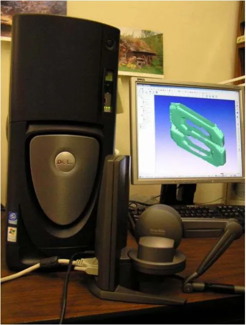
device can make movements). Example of different types of haptic interface device is illustrated in Figure 2.4. With these devices, there have been several related researches in different areas e.g. virtual sculpting, object design and prototyping, surgical simulation, training and practice, and etc. Figure 2.5 illustrates our lab setup haptic device.
Members of our research group have worked with lab setup haptic interface device and applied its abilities to study some research works as show by following:
1. Energy-Field Optimization and Haptic-Based Molecular Docking and Assembly Search System [Lai-Yuen 2006].
2. Energy-Field Optimization and Haptic-Based Molecular Docking and Assembly Search System for Computer-Aided Molecular Design (CAMD) [Lai-Yuen 2005] 3. Five-axis Pencil-Cut Machining Planning and Virtual Prototyping with a 5-DOF
Haptic Interface [Zhu 2004].
4. Dexel-Based Force-Torque Rendering and Volume Updating for 5-DOF Haptic
Product Prototyping and Virtual Sculpting [Zhu 2004].
5. A Marching Algorithm of Constructing Polyhedral Models from Dexel Models for Haptic Virtual Sculpting [Zhu 2005].
6. Virtual prototyping and manufacturing planning by using tri-dexel models and haptic force feedback [Ren 2006].
Early researches used fully-automated approaches to solve sharp edge retaining problem. They depended solely on information and computational strategies of each algorithm, thus made them inflexible and unintuitive. Our method, which is presented in a working paper [Boonma 2006], combines computational techniques and user-interface system through haptic interface device. As a result, users have more freedom and ability to custom-make sharp edge. Our technique is also more flexible and intuitive since users can see the sharp edge during working and they can decide whether they are satisfied with the result or they want to re-specify the parameters and re-create sharp edge again until satisfied.
2.5
Summary
In this chapter, we briefly review some of related techniques in 3D virtual object
Chapter 3
Haptic-Based Hole Filling Algorithm
This chapter presents an approach used to repair holes in 3D virtual object. By repairing, we mean to fill the holes with triangular meshes in order to create a watertight
surface model. We focus on a specific hole problem where the defective holes are located at a sharp edge or parting line where two surfaces meet. Our goal is not only to repair the holes, but also to retain sharp edge the surfaces. To achieve the objectives, we propose two major steps. The first step is to automatically create triangular meshes over the hole and the second step, which will be discussed in the next chapter, is to use haptic interface device to detect and help re-creating sharp edge.
3.1
Introduction
In this chapter, we introduce haptic-based hole filling system. In our hole repairing, the input is an incomplete model with a defective hole locating at sharp edge of the object. Example of the incomplete model is shown in Figure 3.1. We begin our approach by applying an automatic hole search algorithm in order to detect the hole. Then, we calculate the hole normal vector, project the hole down onto a reference plane and
Figure 3.1 Example of a model with a defective hole locating at sharp edge
The remainder of this chapter is organized as follows: Section 3.2 presents haptic
interface system for repairing defective surface model. Section 3.3 introduces hole search algorithm. Section 3.4 discusses haptic-based hole filling algorithm. Finally, section 3.5 provides the summary.
3.2
Haptic interface system for repairing defective surface model
We use surface rendering technique rather than volumetric rendering because it is faster and convey sufficient information required for performing the repair operations. Contact point where the virtual tool touches surface of the objects is used for haptic rendering since it is simple and consumes less computational resources.
In this paper, we will use the following notations: (1) virtual tool shown on the screen represents the point that haptic device is currently at, (2) haptic probe is the handheld input device moved and operated by the users.
Figure 3.2 Our lab setup haptic interface device.
3.3
Hole Search Algorithm for locating holes in surface models
In this section, hole search approach that is used to automatically locate holes in the
input model is discussed. We employ hole search algorithm introduced by [Chua 2003] in our work. The algorithm consists of two major parts. The first part searches for all boundary edges which have only one triangle adjacent to it. Then the second part of the algorithm sorts all boundary edges obtained from the first part and forms them into a loop. Hole search algorithm must be performed according to this order, boundary edge search and then edge sorting.
The boundary edge search is simple and can be described by the following steps in reference to Figure 3.3. Boundary edges are also displayed as the darken line in the Figure.
1. For each edge eij in the model, search for an edge eji which is in the opposite
direction of the edge eij.
2. If edge eji does not exist, save it in a list.
3. Repeat step 1 until all edges in the model are considered.
Boundary edge
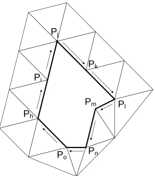
After we get all the boundary edges, start sorting these edges such that they are consecutively connected and form a loop shape (first point of the first edge is the same as end point of the last edge). The edge sorting, as shown in Figure 3.4 can be described by the following steps.
1. Get a boundary edge eij from the list created during boundary edge search and put it in a temporary list.
2. Search in the boundary edge list for an edge whose starting point is point Pj. If such edge is found, put it at the end of the temporary list.
3. In the temporary list, test if the end point of the last edge is the starting point (Pi)
of the first edge. If the result of the test is TRUE, set all edges in the temporary list as a boundary of the hole, clear all edges in the temporary list and repeat step 1 in case there are still some edges left in the boundary edge list. Otherwise, repeat step 2.
P
jP
iP
kP
lP
hP
mP
nP
oThe edge sorting was constructed such that it can handle the situation where holes do not have any coincident point as illustrated in Figure 3.4. We don’t consider the case where two or more holes have a coincident point as shown in Figure 3.5. Solution to such situation can be found in [Chua 2003].
Figure 3.5 Holes with a coincident point.
After hole search, we have a list of holes containing loops of connected edges. Each loop represents a hole in the model. Our program allows the user to select a hole that is to be repaired. The user can select the hole by first moving the virtual tool to the location where the desired hole is located. When the tool is close enough to the hole, the hole will be highlighted automatically to let the user know which hole he/she is going to work on. Then the user can presses the button on the haptic probe while the probe is making
3.4
Haptic-Based Hole Filling Algorithm for repairing defective holes
After user makes selection, the chosen hole is automatically repaired using hole filling
algorithm and followed by triangle subdivision. Surface smoothing algorithm will be done after sharp edge retaining process. Major steps of our hole filling algorithm can be shown in Figure 3.6.
Our algorithm shown above is simple and straightforward. At the end, we obtain the hole filled with un-oriented triangles which will be improved later by surface smoothing technique. Let us describe more details of each step involved in our hole filling algorithm, beginning with the computation of hole normal vector, rotational matrix and reference plane set up. These early steps are discussed in section 3.4.1.
3.4.1
Creating Reference Plane for boundary points projection
We decided to create triangle patches to cover the hole in 2D since it is rather easy to do the computations. Also, a simple intersection test between the new created triangle and the hole boundary can be used. What we need to do first, is to transform the hole coordinate system into 2D by projecting all hole boundary points onto a plane. This plane is called reference plane. To create the reference plane, the hole normal vector, which will
be used as normal vector of the reference plane, is calculated by averaging normal vectors of surrounding triangles (hole boundary triangles) [Jun 2005]. Illustrative example of hole normal vector calculation is found in Figure 3.7.
After the reference plane is created, we project all hole boundary points onto the reference plane by calculating a rotational matrix. This matrix is meant to rotate the reference plane to the angle that normal vector of the reference plane points to positive Z direction. If we apply the same rotational matrix to all hole boundary points, their projections on the reference plane are simply the X and Y coordinates [Jun 2005]. Up to this point, we have the hole boundary lying on a 2D plane. What we want to do next is to eliminate connected boundary edges that make the angles smaller than a predefined value. The “closing predefined angle” will be discussed next, in section 3.4.2.
3.4.2
Closing Predefined Angle to facilitate triangulation
After we have the defective hole lying on a 2D plane, the next step is to eliminate the angle between two boundary edges that is smaller than a predefined value. We do this by moving around the hole perimeter and obtain two consecutive edges. From these two edges, e.g. edge eij and ejk, we calculate the angle between them and check whether the angle is smaller than a predefined value. If the angle is indeed smaller, we then perform intersection test if we create new triangle ΔPiPkPj and replace edge eij and ejk by edge eik. The test is to check if the newly created triangle intersects with any of the hole boundary edges, as shown in Figure 3.8. If such intersection is detected, triangle ΔPiPkPj cannot be created and the search moves over to check the next two connected edges. On the other
hand, if no intersection is found as shown in Figure 3.9, we create triangle ΔPiPkPj and replace edge eij and ejk by edge eik. Repeat the steps until no small angle between any two consecutive edges is detected or the hole is completely filled with newly created triangles.
After testing with some values, setting the angle to
9 5π
gave satisfied result [Tekumalla
Figure 3.8 Intersection of ΔPiPkPjand other existing triangles in the model.
Figure 3.9 No intersection between triangle PiPkPj and other existing triangles in the model.
Our selected hole at this stage is simpler to be repaired since we already
3.4.3
Triangulation over the hole area
After closing small angles, we do triangulation over the hole area in order to fill the
hole with triangles. Basic idea of this step is for each hole boundary edge eij, we search for another hole boundary point Pk that is closest to both point Pi and Pj. The new triangle
P
Δ iPjPk created from the closest point Pk must not intersect with any hole boundary
edges as shown in Figure 3.10. If it intersects, we cannot create this triangle and have to look for another possible point. The algorithm, as described below, in the form of pseudo code will be repeated and creates new triangle along the hole boundary edges until the hole is completely filled.
Algorithm_II. Triangulation over the hole Input: a hole represented by hole boundary edges
Output: filled hole with bulky triangles
WHILE (hole is not completely filled) {
SAVE all hole boundary point into buffer point list REPEAT
{
GET an edge eij from hole boundary edges list FOR (all points in buffer point list)
{
COMPUTE square distance between a point in buffer point list and first and end point of the current edge
}
GET the point Pk that has minimum sum of square distances
/* Check whether new triangle ΔPiPjPk can be created. Test passes if no intersection is detected */
INTERSECTION_TEST IF (no intersection detected) {
CREATE triangle ΔPiPjPk and edge ejk and eki /* Update hole boundary edges */
{
DELETE point Pk from buffer point list }
} UNTIL (no point left in buffer point list or new triangle ΔPiPjPk can be created) }
END
In INTERSECTION_TEST, we check whether the to-be-created triangle intersects
with any existing hole boundary edges. If it does, the to-be-created triangle must not be constructed. We then skip the current edge and obtain the next one. On the other hand, if the to-be-created triangle does not show any intersection with any of the hole boundary edges, we are free to construct the triangle. Figure 3.10 shows that triangle ΔPiPjPk, which passes the intersection test (it does not intersect with any of the hole boundary edges), is created, while the triangle ΔPiPmPj must not be created since it shows intersection with one of the other hole boundary edges. The algorithm will be repeated until the hole is completely filled as shown in Figure 3.11.
Figure 3.11 The hole filled by Triangulation.
After completely filling the hole, as displayed in Figure 3.11, we multiply all of the projected hole boundary points with the reverse rotational matrix in order to turn them back into the original coordinate system. Up to this point, our incomplete model is refilled with large triangle and becomes a watertight one.
In order to increase resolution and improve accuracy of the newly created triangle patches, in the next process, we will subdivide those triangle patches into smaller pieces.
This upcoming process is called subdivision.
3.4.4
Subdivision
we reach the predefined value, the algorithm will stop. We employ refinement algorithm introduced by [Liepa 2003] in our work and the steps involved in the algorithm are as shown by following.
Algorithm_III. Subdivision
Input: a triangulate facet model with bulky repaired triangles Output: a triangulate facet model with smaller repaired triangles
DO {
COUNT number of times that the algorithm runs this loop SET starting triangle to the first triangle in the list, e.g., ΔPiPjPk
WHILE (at least one triangle has not been considered) {
createNewTri=FALSE;
IF (the triangle being considered is already considered in this running loop) {
CONTINUE /* go back and get another triangle */ }
COMPUTE average length of all edges connecting to each vertice of the triangle being considered, obtaining scale attributes σi, σj and σk
COMPUTE the average value σc by averaging σi, σj and σk
COMPUTE centroid of the triangle being considered (Pc)
COMPUTE distance between each vertice and the centroid, and multiply the each distance value by a square root, obtainingdisti,distj and distk
IF( (disti > σc and disti > σi) or (distj > σc and distj > σj) or
(disti > σc and disti >σk))
{
/* subdivision */
SET createNewTri = TRUE
SUBDIVIDE the triangle being considered into 3 pieces; CONTINUE; /* exit the loop */
}
IF( createNewTri = FALSE ) /* if no subdivision or no new tri created*/ {
/* mesh is complete */ BREAK;
}
/* relax all interior edges of triangles*/ DO
{
SET starting triangle to the first triangle in the list interiorEdgeSwap=FALSE;
WHILE( at least one triangle has not been considered ) {
FOR(each edge of a trianalge) {
IF(the edge is not boundary edge, and not considered before) {
/* check to relax this edge with its neighbor triangle */ IF( pass criterior to do interior edge swap )
{
interiorEdgeSwap=true;
break; // if relax this edge, consider next tri }
} } }
} WHILE ( interiorEdgeSwap );
/* if we swap any of the interior edge, check to do swap until no swap is found */ } WHILE ( createNewTri && (count!=preset value) );
/* if we subdivide a triangle, keep do it until no subdivision occur. */ END
shared edge eij. Edge eij can be swapped if vertex Pk is inside the circum-sphere of the triangle ΔPiPmPj as shown in Figure 3.13. This edge swap process is called edge relaxing [Liepa 2003].
Pj Pk
Pi
Pc
Figure 3.12 Splitting Triangle. TriangleΔPiPjPk is replaced by triangle PiPjPc, PjPkPc and PkPiPc
Figure 3.13 shows edge relaxing method. (a) before relaxing edge eij, point Pk is inside the circum-sphere of triangle ΔPiPmPj. (b) after relaxing, edge eij becomes edge ekm.
provides satisfied result. This setting could speed up the computation and limit number of triangles being produced.
The hole is now filled up with smaller triangles as we would like it to be. These triangles will be called repaired or hole triangles throughout the rest of this paper. After subdivision process, if the hole is not located at the sharp edge, we can apply surface smoothing algorithm and we should be able to get watertight model with better surfaces that approximate the curvature of hole boundary triangles.
3.5
Summary
In this chapter, we have presented the haptic-based hole filling for repairing defective holes. The problem becomes more interesting if hole is located right at the sharp edge of the part. In such case, hole filling algorithm alone is not sufficient to repair the incomplete
Chapter 4
Haptic-Based Sharp Edge Retaining
and Gap Bridging Algorithm
This chapter presents two approaches: (1) haptic-based sharp edge retaining algorithm for creating sharp edge over defective holes, (2) haptic-based gap bridging algorithm for sealing the gap between two triangulated surfaces. For the first technique, we focus on a specific problem where a defective hole is located at a sharp edge of the
part. Our input is a watertight model which is the result of the hole filling algorithm as discussed in previous chapter.
4.1
Introduction
For an incomplete model that a defective hole lies on its sharp edge, we first use hole filling algorithm that we presented in the previous chapter to re-create surface patches over the hole (repaired triangles). Then, sharp edge retaining algorithm is required to recover the sharp edge at the hole area.
With a hole-filled model as our input, haptic interface device is used to specify four points along the sharp edge on the hole boundary surface. These points are inputs for our algorithm in order to create a Hermite curve approximating the sharp edge and the guiding surface across the hole. The repaired triangles intersected by the guiding surface are re-aligned according to the guiding surface and users can make adjustment to those
triangles by moving them down either to the satisfied level or to the pre-calculated sharp edge (which is represented by the Hermite curve). The final process is to smooth the created triangles using simple surface smoothing algorithm.
device. The inputs of our system are two perfectly registered surfaces. The haptic interface device can be used to 1) manually create triangles such that they connect these two surfaces together or 2) manually create two triangles at both sides of the gap such that the gap turns into a hole. Then, the traditional hole filling algorithm is applied. The result of this algorithm is refilled gap and two surfaces are merged together.
The remainder of this chapter is organized as follows: Section 4.2 describes haptic-based sharp edge retaining algorithm. Section 4.3 introduces haptic-based gap bridging algorithm. Finally, section 4.4 provides the summary.
4.2
Haptic-Based Sharp Edge Retaining Algorithm
In this section we introduce haptic-based sharp edge retaining algorithm. Previous works create sharp edge if normal vectors of triangle patches representing the surfaces are
obviously different. Those algorithms, therefore, are suitable for industrial parts where the information of sharp edge can be extracted from the hole boundary surfaces.
In our work, we would like to show that not only in the industrial parts that sharp edge can be created, but it also can be obtained in the free-form model where the shape of sharp edge is not well defined. We use haptic interface device to capture information of sharp edge from the hole boundary triangles. Then, the information is used to align the hole triangles in order to facilitate changing position of the triangles along the approximated sharp edge. To create sharp edge, the user can now either push these triangles down to their preferred level or to the approximated level that the algorithm calculates. Simple surface smoothing algorithm is performed next so that the triangles
Figure 4.1 Algorithm IV: haptic-based sharp edge retaining algorithm
approximate the sharp edge over the hole. The concept of Hermite curve can be described in the next section.
4.2.1
Constructing Hermite Curve and Guiding Surface
Hermite curve is a form of cubic polynomial curve [Foley 1996]. It can be defined by end point P1, P4 and the tangent vector R1 and R4 at end point P1 and P4 respectively. Hermite curve can be represented by the following equation.
H H G M T t z t y t x t
Q( )=[ ( ) ( ) ( )]= • • (1)
Where GH is the column vector . ⎥ ⎥ ⎥ ⎥ ⎦ ⎤ ⎢ ⎢ ⎢ ⎢ ⎣ ⎡ 4 1 4 1 R R P P
MH is Hermite basis matrix which is uniquely defined as
⎥ ⎥ ⎥ ⎥ ⎦ ⎤ ⎢ ⎢ ⎢ ⎢ ⎣ ⎡ + + − − + − + + − + 0 0 0 1 0 1 0 0 1 2 3 3 1 1 2 2
Length of tangent vector at R1 and R4 affects the shape of Hermite curve. The longer the length of tangent vectors, the greater their effects are to the curve [Foley 1996]. Thus,
the geometry vector must have the form , with k ⎥ ⎥ ⎥ ⎥ ⎦ ⎤ ⎢ ⎢ ⎢ ⎢ ⎣ ⎡ 4 1 4 1 R R P P ⎥ ⎥ ⎥ ⎥ ⎦ ⎤ ⎢ ⎢ ⎢ ⎢ ⎣ ⎡ 4 4 1 1 4 1 r k r k P P
1 and k4 > 0. The variable
k1 and k4 are determined based on experimental basis in order to get the curve that best satisfies the user. The example of a Hermite curve created from four selected points is
A point selected using haptic interface device
Figure 4.2 Example of four points (P1-P4) selected using haptic interface device, order of points selection and the constructed Hermite curve.
In our program, point P2 and P3 will respectively be our start and end point of the Hermite curve. Tangent vector r1 at point P2 is a unit vector from point P1 to P2, while the tangent vector r4 at point P3 is a unit vector from point P3 to P4. Depending on the example model we used, we set number of points on the Hermite curve such that each segment between points is approximately the length of edge of triangles around hole boundary. Number of points also represents number of line segment that we want to have
Hermite curve
Repairing triangles created by hole filling algorithm. Hole boundary
Figure 4.3 Hermite curve created from four selected points. The curve approximates sharp edge between bottom surfaces and the mouse.
After having the Hermite curve, we extrude it in the direction of hole normal vector and the direction opposite to hole normal vector. The extruded points are used in triangulation in order to create a guiding surface onto the Hermite curve as shown in Figure 4.4. Figure 4.5 illustrates the constructed guiding surface in a mouse model. The
Guiding surface Hermite curve
Figure 4.4 The guiding surface created from Hermite curve
Guiding surface
Figure 4.5 The guiding surface in the mouse model
4.2.2
Vertices Snapping for re-aligning triangle vertices onto the
guiding surface
In vertices snapping, we re-align some vertices of the triangles through which the guiding surface passes such that they are located on the guiding surface. Vertices snapping will facilitate surface deformation in the later stage where we use the haptic
probe to push down the triangles along the guiding surface to the Hermite curve that approximates the sharp edge.
In this process, we search along the guiding surface for the repaired triangles through which the surface passes. Then, for each repaired triangle, we find a vertex that is located closest to the guiding surface and snap it onto the guiding surface. Vertices snapping can be done by following steps.
Algorithm_V. Vertices Snapping for re-aligning triangle vertices onto the guiding surface
Input: hole triangles
Output: aligned hole triangles
FOR (all hole triangles) {
FOR (all edges of the current triangle) {
IF (the current edge intersects with the guiding surface) {
GET the intersection point between the current edge and the guiding surface GET the closest end point to the intersection point and is located on this edge.
IF (the end point we obtained is not hole boundary points) {
SET the end point to the intersection point as shown in Figure 4.6. }
Figure 4.6 shows the alignment of hole triangles before and after being applied by our vertices snapping algorithm, while Figure 4.7 shows another example of our algorithm in the mouse model.
Figure 4.6 Vertex snapping. (a) Triangular meshes before vertex snapping. (b) Triangular meshes after vertex snapping.
Vertex at the
beginning of the
arrow is moved to
the intersection
point between the
edge it belongs to
and the guiding
surface.
4.2.3
Surfaces modification using haptic interface device
After aligning triangles through which the guiding surface passes, we push all those
triangles down using haptic interface device. The user can first specify how much he/she wants to move these triangles (specify the distance that the triangles will be moved each time when they are in contact with the virtual tool). Then, the user sweeps the tool along the intersection line between the guiding surface and the reconstructed triangles. Hand shaking problem is minimized since the tool is snapped onto the guiding surface. Each time a triangle is touched by the virtual tool, it will be moved down with pre-specified distance until it reaches the Hermite curve or the user stops sweeping the tool. The algorithm used in this process can be described as follows:
Algorithm_VI. Surfaces Modification Using Haptic Interface Device
Input: A hole triangle, proxy point at current time step and proxy point at previous time step. Proxy point is the position of the virtual tool.
Output: A hole triangle with sharp edge.
GET two proxy points, one at the previous time step and another at the current time step, and the triangle that the virtual tool is currently on.
COMPUTE the direction of movement of the tool from the two proxy points FOR (all vertices of triangle that the virtual tool is currently on)
{
COMPUTE distance between the vertex and the line representing the tool movement direction.
}
GET a vertice that is closest to the line representing tool movement direction. COMPUTE the final position of the vertex if it is touched by the virtual tool. IF (the pre-computed final position passes the Hermite curve)
{
MOVE the vertex to intersection point between the line connecting the current position and the pre-calculated position of the vertex, and the Hermite curve.
} END
The above algorithm is repeated until the user is satisfied or the vertices of deformable triangle reach the Hermite curve. Next, our final step is to orient hole triangles in order to smooth the surfaces.
4.2.4
Surface smoothing
After the user is satisfied with the sharp edge he/she created using haptic interface device, surface smoothing algorithm is used to smooth other hole triangles such that they approximate the curvature of the hole boundary surfaces.
The concept of our surface smoothing algorithm is that; we want to search along visited edges. Visited edge refers to an edge that consists of hole boundary points, fixed points or belongs to fixed triangle. Points and triangles are treated as fixed or unable to be modified when they are located on the hole boundary, on the guiding surface, or when they are already moved. Considering triangle ΔPiPjPk, if point Pk is not fixed and edge eij is a visited edge. Point Pk can be improved by the following steps.
1. Calculate average of normal vectors of hole boundary triangles surrounding the visited edge.
2. Move the movable point such that normal vector of the triangle, to which the point and the visited edge belong, is the same as the average normal in step 1.
The algorithm is repeated until all the hole triangles are considered (all triangles are
Algorithm_VII. Surface Smoothing Input: hole triangles
Output: smoothed hole triangles
/* Set value of all related points and edges */
SET hole boundary points and points on the guiding surface to “fixed”. SET hole boundary edges to “visited”
/* Get the normal information of surrounding triangles */ FOR (all hole boundary points)
{
COMPUTE a normal vector Ni at a current hole boundary point Pi by averaging normal vectors of all boundary triangles surrounding the point Pi.
}
REPEAT {
WHILE (at least one hole point left unconsidered) {
/* Check the type of point */
GET a hole point by marching along the visited edge CLASSIFY_POINT
IF (hole point is type 1) {
SET this point to considered MODIFY_POINT1
UPDATE_SURROUNDING_TRIANGLE }
IF (hole point is type 2) {
SET this point to considered MODIFY_POINT2
UPDATE_SURROUNDING_TRIANGLE }
}
} UNTIL (no hole point is modified in above process) /* all triangles are fixed. */ END
CLASSIFY_POINT is the process used to classify the point being considered. If the point is already fixed, we check all the triangles surrounding the point whether all vertices of each of them are also fixed. If result of the test is TRUE, we set the corresponding triangle to “fixed” triangle. On the other hand, if the point is not fixed, we then find a number of triangles that satisfies two requirements. First, the triangle must have one visited edge. Second, the triangle must have the point being considered as one of its vertex. If number of triangles satisfying these requirements is one, the point is categorized as type one. Otherwise, the point is categorized as type two.
In MODIFY_POINT1, if the point being considered is point Pk, the visited edge is eij having end point Pi and Pj and the corresponding triangle is triangle ΔPiPjPk, we
calculate the average normal avgNij of normal vectors Ni and Nj at point Pi and Pj respectively. Then, we rotate the point Pk around the edge eij such that the final location of point Pk makes normal vector of the triangle ΔPiPjPk equal to the average normal avgNij. Finally, we set point Pk to fixed point and set the triangle ΔPiPjPk to fixed triangle.
In MODIFY_POINT2, we follow the same process as in MODIFY_POINT1 except that we have more than one triangle in consideration. Therefore, we calculate the location of point Pk for each triangle and then average them all to get the approximated location for point Pk. Finally, we set point Pk to fixed point and set all corresponding triangles to fixed triangles.
Lastly, in UPDATE_SURROUNDING_TRIANGLE, we check all the triangles surrounding new fixed point Pk. If all vertices of each of the surrounding triangles are also fixed, we set the corresponding triangles to fixed triangles and then recalculate their normal vectors. Also, all edges of the fixed triangles are set to visited edge.
4.3
Haptic-Based Gap Bridging Algorithm
In this section, haptic-based gap bridging algorithm is presented. We introduce two
methods to repair defective gaps in triangular mesh model. The first method is for the user to use haptic interface device to manually connect or stitch two surfaces together. This method might be slow and tedious but it is quite simple to understand and easy to apply in gap bridging problem. User can also control the shape of the created triangles. Another method is to let user manually create only two triangles enclosing the gap. Then, the gap becomes a hole and can be repaired using simple hole filling algorithm.
4.3.1
Manual Gap Bridging Algorithm
Basic steps of manual gap bridging algorithm are presented in Figure 4.8. We begin with a model with a defective gap separating two surfaces. The surfaces, our input, are assumed to be perfectly registered and ready to be repaired. Readers are referred to Figure 4.9 for visual display of this algorithm.
This algorithm needs to have a pre-processing step. That is, we must let the system
An incomplete model with gaps
Is the user satisfied with the resulting triangle?
Search for and set boundary edges into a list
Move the virtual tool to a triangle adjacent to boundary edge
Make selection by pressing the button on the haptic probe and then drag the triangle toward
target boundary point on another surface
Release the button to confirm newly created triangle
Is the gaps completely repaired?
A complete model with gaps repaired
No
Yes
No
Yes
Figure 4.9 Manual Gap Bridging. User uses haptic interface device to manually repair the defective gap. (a) Original surfaces. (b) Haptic interface device is repairing the defective gap. (c) Complete repaired model.
When the user makes selection of a boundary triangle, the system does the following tasks.
IF( the button is pressed) {
DrawNewTriangle(); /* draw new generate triangle */ DrawPoints(); /* draw boundary points */ GetGroupSnapPoints(); /* Get list of possible snap points */
GetSnapPoint(); /* Get a snap point closest to virtual tool */ IF(number of possible snap points > 0)
{
HIGHLIGHT the point }
On the other hand, when the user releases the button to confirm new triangle creation, the system does the following tasks.
SET the flag to indicate that the button is not pressed any more IF(number of possible snap point > 0)
{
SET new vertex to the closest snap point SET new triangle
CLEAR the list of possible snap points }
This algorithm is easy to understand and simple to use especially for a gap that has relatively short length. However, it becomes quite tedious if the length of the gap is long. Therefore, in the following section, we introduce another algorithm that might be useful in repairing lengthy gaps.
4.3.2
Semi-automatic Gap Bridging Algorithm
We present a semi-automatic gap bridging algorithm in this section. Basic steps of the algorithm are presented in Figure 4.10. We begin with a model with a defective gap separating two surfaces. The surfaces, as our input, are assumed to be perfectly registered and ready to be repaired. Readers are referred to Figure 4.11 for visual display of this
algorithm.
Figure 4.10 Algorithm IX: Semi-automatic gap bridging algorithm
The semi-automatic gap bridging algorithm eliminates some tedious works (e.g. when using the manual algorithm, the user needs to manually create triangles until the defective gap is completely repaired) and is much faster than manual gap bridging algorithm. However, it is less flexible in the sense that the user cannot control the shape of created triangles since the gap is filled by automatic hole filling algorithm.
4.4
Summary
In this chapter we present a few approaches to repair defective holes with sharp edge retained, and defective gaps in 3D virtual object. Haptic interface device plays an important role in our technique. It is user-friendly and its ability to access and feel the 3D object in virtual space makes it easier to manually create or repair triangular meshes. In the next chapter, we will show some illustrative examples of our haptic-based hole filling,
Chapter 5
Examples and Results
In this chapter, system implementations and illustrative examples of the proposed algorithms are presented. The proposed methods have been implemented on a dual 2.4
GHz CPU workstation using Microsoft® Visual C++ and OpenGL® library at our research lab. The implemented system has been integrated with a PHANTOM Desktop™ Haptic Interface Device from SensAble Technologies and implemented using the OpenHaptic™ toolkit.
5.1
Examples of models with Sharp Edge Resulted From Haptic-Based
Hole Filling and Sharp Edge Retaining Algorithm
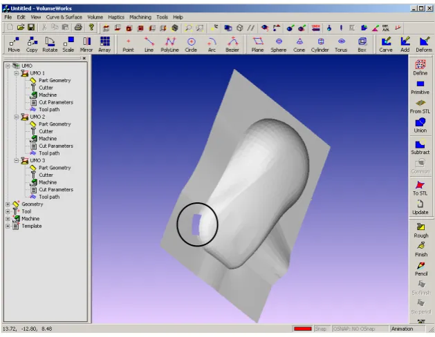
Figure 5.1 shows the general concept of the proposed haptic-based hole filling and sharp edge retaining algorithm. Having a 3D virtual object model in the form of STL file format as the input, the user can use haptic interface device to touch and feel the surface of the object. Figure 5.2 illustrates the implemented haptic-based system and the user interface. Whenever the user moves the virtual tool into an area close enough to a defective hole, the hole boundary will be highlighted. Then, if the user would like to repair the hole, he/she can initiate haptic-based hole filling algorithm by simply pressing a button on the haptic probe. The selected hole will be automatically repaired using a series of methods which we already described in Chapter 3. The final result of haptic-based hole
To initiate haptic-based sharp edge retaining algorithm, the user is required to select four points along the sharp edge on the hole boundary surface as we described in Chapter 4. These points will be used to create a Hermit curve which approximates sharp edge across the hole area. After that, the algorithm generates a guiding surface such that it passes through the Hermite curve and penetrates through repaired surfaces over the hole. The repaired triangular patches through which the guiding surface penetrates are re-aligned such that their vertices located closest to the guiding surface are snapped onto the guiding surface. This vertices snapping is not applied for the hole boundary points. Then, the user is free to use haptic probe (represented as the virtual tool on the screen) to
Figure 5.2 Our lab setup haptic interface device
The next few figures show examples of the haptic-based hole filling and haptic-based
sharp edge retaining algorithm. Figure 5.3 illustrates our first example, the mouse model. The model has a defective hole at the bottom left corner of the mouse body and exactly on the sharp edge. We used our haptic-based hole filling and sharp edge retaining algorithm to repair and create the sharp edge over the defective hole. Figure 5.4 shows the model after hole-filled and four points are selected for generating a guiding surface. Figure 5.5 illustrates the guiding surface and the repaired surface being pushed down by the haptic interface device. The resulted model after sharp edge retained is shown in Figure 5.6.
The repaired sharp edge illustrated in Figure 5.6 is created by setting the Hermite’s slope parameter k1 and k2 = 15. The parameter k1 and k2 can be thought of as the length of
Figure 5.3 A mouse model with a defective hole at the bottom left corner. The blue cursor floating on top of the object is our virtual tool.
Figure 5.5 The guiding surface and the repaired surface being pushed down by the haptic interface device
![Figure 2.2 A sphere model with defective holes [Liepa 2003].](https://thumb-us.123doks.com/thumbv2/123dok_us/1487645.1182009/21.595.237.403.358.541/figure-sphere-model-defective-holes-liepa.webp)
![Figure 2.3 The repaired sphere model [Liepa 2003]](https://thumb-us.123doks.com/thumbv2/123dok_us/1487645.1182009/22.595.236.397.217.380/figure-repaired-sphere-model-liepa.webp)
![Figure 2.4 Examples of haptic interface devices [Salisbury 2004]: (a) force-reflecting](https://thumb-us.123doks.com/thumbv2/123dok_us/1487645.1182009/25.595.91.522.192.564/figure-examples-haptic-interface-devices-salisbury-force-reflecting.webp)