ABSTRACT
MOUSA, MOATAZBELLAH MAHMOUD. High Throughput Atomic Layer Deposition Processes: High Pressure Operations, New Reactor Designs, and Novel Metal Processing. (Under the direction of Gregory N. Parsons).
Atomic Layer Deposition (ALD) is a vapor phase nano-coating process that deposits very uniform and conformal thin film materials with sub-angstrom level thickness control on various substrates. These unique properties made ALD a platform technology for numerous products and applications. However, most of these applications are limited to the lab scale due to the low process throughput relative to the other deposition techniques, which hinders its industrial adoption. In addition to the low throughput, the process development for certain applications usually faces other obstacles, such as: a required new processing mode (e.g., batch vs continuous) or process conditions (e.g., low temperature), absence of an appropriate reactor design for a specific substrate and sometimes the lack of a suitable chemistry.
using the ALD delivery head. Another process development shown herein is the
improvement achieved in the selective synthesis of organic-inorganic materials using an ALD based process called sequential vapor infiltration. Finally, the development of a new ALD chemistry for novel metal deposition is discussed and was used to deposit thin films of tin metal for the first time in literature using an ALD process.
High Throughput Atomic Layer Deposition Processes: High Pressure Operations, New Reactor Designs, and Novel Metal Processing
by
MoatazBellah Mahmoud Mousa
A dissertation submitted to the Graduate Faculty of North Carolina State University
in partial fulfillment of the requirements for the Degree of
Doctor of Philosophy
Chemical Engineering
Raleigh, North Carolina 2015
APPROVED BY:
_______________________________ _______________________________ Dr. Gregory N. Parsons Dr. Saad A. Khan
Committee Chair
DEDICATION
To my father, Mahmoud, and my mother, Mervat, for your unconditional love and support. To my brother, Moatasem Bellah, for the fun of learning together.
BIOGRAPHY
Moataz Bellah Mousa was born and raised in Cairo, Egypt. After receiving his international general certificate of secondary education (IGCSE), he earned his bachelor’s and master’s degrees in chemical engineering from Cairo University in 2007 and 2010, respectively. During his M.Sc. studies, he worked as a teaching assistant where he assisted the instruction of multiple courses including transport phenomena and materials engineering. His master’s research was focused on developing new reactor designs using computational fluid dynamics (CFD) modeling. In fall 2010, he pursued a Ph.D. in chemical engineering at North Carolina State University under the guidance of Prof. Gregory Parsons. His research focused on thin films deposition and characterization using atomic layer deposition (ALD) processes for applications in polymers modification, surface passivation, and metal coatings for
microelectronic devices. He also expanded his experience in reactors design during his Ph.D. years and worked on developing new ALD reactors and chemistry. Along with pursuing his research interest in thin films deposition, Moataz also followed his interest in
ACKNOWLEDGMENTS
I would like to express my sincere gratitude to several people in the next few lines, without them you would not have been reading these lines. First and foremost, my advisor Prof. Gregory Parsons, who taught me the research attitudes and ethics through being an exemplary eager scientist. He guided me whenever needed and gave me enough space to explore new ideas. Second, my parents, Mahmoud Mousa and Mervat El-Shaarawy, no words can thank you enough but I quoted this proverb for you “One can pay back the loan of gold. But one dies forever in debt to those who are supportive, kind, sacrificing and always caring and sharing”.
To my wife, Hadia Elhadidy, your steady support and smile got me to overcome many setbacks. I cannot imagine how I would have achieved any of this without you being by my side. Thanks for being who you are. For my almost one year old son, future scientist, thank you for putting a smile on my face no matter what was going on.
A million thanks to all of the past and present members of Parsons’ research group, you made it tough for me to easily enjoy working anywhere else. It was a pleasure to work, chill and travel with all of you. Thank you for the amazing memories that I will cherish forever. For the Egyptian fellows in Raleigh, thank you for making this city a home away from home. We had a lot of fun together and looking forward to meet all of you again in Egypt. Special acknowledgement is due to Dr. Mohammed Gamal, we have been together through B.S., M.S. and Ph.D. and now it is time to say “until we meet again”.
TABLE OF CONTENTS
LIST OF FIGURES ... viii
CHAPTER 1: Introduction and Background ... 1
1.1 Atomic Layer Deposition (ALD) ... 2
1.1.1 Process Overview ... 2
1.1.2 ALD in Manufacturing ... 4
1.1.3 ALD Reactors ... 6
1.1.4 Atmospheric Pressure Atomic Layer Deposition (AP-ALD) ... 8
1.1.5 Sequential Vapor Infiltration (SVI) ... 10
1.2 Metals and Metal Oxides ALD ... 11
1.2.1 Metal Oxides Deposition: Water vs Ozone as a Co-reactant ... 11
1.2.2 Metals Deposition by Thermal ALD: Reducing agents ... 13
1.3 Overview of the Key Advances in ALD Presented in this Dissertation ... 16
1.4 References ... 27
CHAPTER 2: Experimental Tools ... 35
2.1 Thin Films Deposition Tools... 36
2.2 Characterization Tools ... 37
2.3 References ... 46
CHAPTER 3: Effect of Temperature and Gas Velocity on Growth per Cycle during Al2O3 and ZnO Atomic Layer Deposition at Atmospheric Pressure ... 47
Abstract ... 48
3.1 Introduction ... 49
3.2 Materials and Methods ... 51
3.3 Results and Discussion ... 53
3.4 Summary ... 61
3.5 Acknowledgements ... 61
CHAPTER 4: Atmospheric Pressure Atomic Layer Deposition of Al2O3 using
Trimethyl Aluminum and Ozone ... 71
Abstract ... 72
4.1 Introduction ... 73
4.2 Materials and Methods ... 76
4.3 Results and Discussion ... 79
4.4 Summary ... 88
4.5 Acknowledgments ... 90
4.6 References ... 98
CHAPTER 5: Precise Nanoscale Modification and Coating of Macroscale Objects: Open-Environment in Loco Atomic Layer Depositon on an Automobile ... 102
Abstract ... 103
5.1 Introduction ... 104
5.2 Materials and Methods ... 105
5.3 Results and Discussion ... 108
5.4 Summary ... 116
5.5 Acknowledgments ... 117
5.6 Supplemental Material ... 123
5.7 References ... 133
CHAPTER 6: Design of a High Throughput Spatial Atomic Layer Deposition Reactor for Functional Nano-coatings on Porous Materials ... 137
Abstract ... 138
6.1 Introduction ... 139
6.2 Materials and Methods ... 143
6.3 Results and Discussion ... 147
6.4 Summary ... 159
CHAPTER 7: Atmospheric Pressure Synthesis of Photoluminescent Hybrid Materials by Sequential Organometallic Vapor Infiltration into Polyethylene
terephthalate Fibers ... 173
Abstract ... 174
7.1 Introduction ... 175
7.2 Materials and Methods ... 177
7.3 Results and Discussion ... 179
7.4 Summary ... 188
7.5 Acknowledgments ... 188
7.6 Supplemental Material ... 197
7.7 References ... 199
CHAPTER 8:Tin Metal Atomic Layer Deposition using Tin(IV) Chloride and a Silyl Dihydropyrazine Reducing Agent ... 203
Abstract ... 204
8.1 Introduction ... 205
8.2 Materials and Methods ... 207
8.3 Results and Discussion ... 210
8.4 Summary ... 220
8.5 Acknowledgments ... 221
8.6 References ... 230
Appendix ... 234
LIST OF FIGURES
Figure 1.1. Aluminum oxide cyclic deposition using ALD process starting with hydroxyl terminated surface. (1 and 2) Methyl terminated surface is formed after Tri-methyl Aluminum (TMA) dosing and purging then (3 and 4) turns to hydroxyl terminated surface again, with formation of Al2O3 atomic layer, after dosing and purging of water.
The occuring half reactions at each dosing step are shown in the figure as well as the net overall reaction. (Adapted with modification from [71]) ... 23
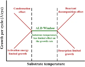
Figure 1.2. ALD process temperature window. The variation of growth with the substrate temperature where self limiting reactions and surface saturation only occur within the ALD window range (green line).. ... 24
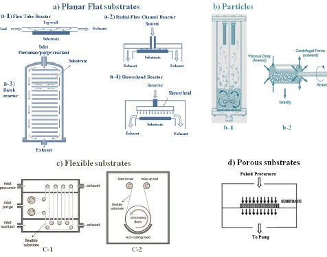
Figure 1.3. Various designs of ALD reactors for different substrate types. A) Planar substrates involve flow of the gases over the surface either for a-1,2,3) single wafer31 or a-4) multiple wafers9. B) Particles of different sizes coated in b-1) fluidized bed
reactor72-74 and b-2) rotary drum reactor75,76. C) ALD reactors for polymer webs and other flexible substrates were illustrated by c-1) Lotus Applied Technologies77 and c-2)
Beneq78, while D) porous substrates79 as fibers and textile materials will require a flow through reactor designs. ... 25
Figure 2.1. Schematic of a home-built modified ALD flow tube reactor that allows for deposition under wide pressure range. The controlled pneumatic val ves positions are not shown. ... 44
Figure 2.2. A schematic for boundary layer (in red) and velocity profile development for laminar gas flow through a tube reactor. ... 45
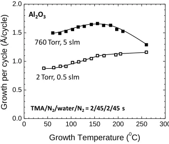
Figure 3.1. Growth per cycle for ALD of Al2O3 as a function of deposition temperature
for reactor pressures of 2 and 760 Torr. Deposition was performed in a reactor system with specially designed gas delivery to allow operation with adjustable pressure. The figure also identifies the gas pulse timing used for deposition. The growth rate is larger at higher pressure, and under the conditions used, the increase is independent of
temperature for T<150 °C. At higher temperatures, the growth rates begin to converge, consistent with the onset of a thermally activated mechanism. ... 62
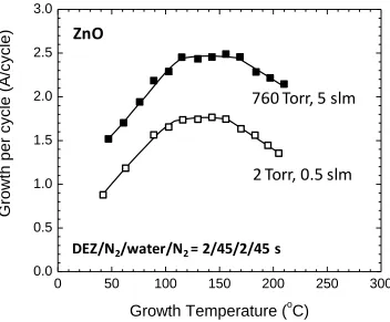
Figure 3.2. ALD growth per cycle for ZnO versus temperature. The thickness per cycle at 760 Torr is larger than at 2 Torr for all temperatures between 40 and 200 °C. The gas pulse conditions used for deposition are identified in the figure. ... 63
Figure 3.3. Growth per cycle of Al2O3 at 760 Torr and 130 °C versus water purging time
for several values of N2 purge gas flow rate. Increasing flow rate increases gas velocity
and tends to reduce the growth rate for ALD Al2O3, at 0.7 m/s flow velocity, the growth
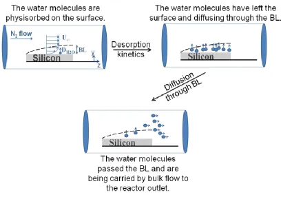
Figure 3.4. Schematic diagram showing the diffusion of physisorbed water molecules from the substrate surface and becoming entrained in the bulk purge gas flow. ... 65
Figure 3.5. AFM images for Al2O3 coatings on silicon substrate at (a) low and (b-e)
high pressure depositions. The film deposited at (a) 2 Torr was found to be smooth with roughness about ~0.19 nm. For high pressure depositions, the films got smoother with the increase in purge gas flow rate. The scanned areas were 4x4 m for all of the
samples and the scale bar maximum value is 5 nm. ... 66
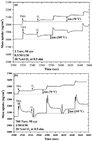
Figure 4.1. Growth per cycles showing saturation behavior of atomic layer deposited Al2O3 layers using O3 and TMA at 2 Torr and 205 oC with: (a) fixed TMA dose time; (b)
fixed O3 dose time. The error bar reflects a typical ±5% uncertainty in the thickness measurement. Quartz crystal microbalance mass uptake using: (c) one TMA dose followed by three ozone doses; and (d) three TMA doses followed by one O3 dose.
Repeated O3 or TMA doses show no mass uptake, confirming with fully saturated
growth. ... 91
Figure 4.2. Growth per cycle for Al2O3 versus O3 dose time at: (a) 2 Torr; and (b) 760
Torr for different deposition temperatures. The error bar reflects a ±5% uncertainty in the thickness measurement. The growth per cycle shows that a longer exposure time is needed for saturation at high pressure. ... 92
thickness per cycle at 2 Torr (0.5 slm purge flow rate) and 760 Torr (3 and 10 slm). The error bar represents typical ±5% uncertainty in the thickness measurement. ... 93
Figure 4.4. Mass uptake using in-situ QCM vs. processing time for cycles of TMA/O3 at
(a) 2 Torr and (b) 760 Torr at 70 oC and 205 oC. Mass increases during TMA doses for both temperatures but slightly decreases during O3 at 205 oC and showed large increase
at 70 oC. ... 94
Figure 4.5. Refractive index at 600 nm calculated using Cauchy model for thick Al2O3
films deposited at different temperatures at 2 Torr and 760 Torr. The index decreases when the temperature is below the ALD temperature window. ... 95
Figure 4.6. ToF-SIMS depth profiles for Al2O3 deposited at 205°C and: a) 2 Torr; b)
760 Torr. Similar film composition is attained. ... 96
Figure 4.7. Lines represent model results for O3 molar flow rate along the reactor under
2Torr and 760Torr at 100 OC, 150 OC, and 205 OC. The ozone molar flow rate at the inlet was ~6.8x10⁻⁵ mol/sec (20 wt. % at 0.5slm), and the gas velocity was 0.10-0.13 m/s (corresponding to ~5.5 slm) at 760 Torr, and 6.2-7.9 m/s (~ 0.75 slm) at 2 Torr. Data points (triangular and crossed square) represent experimental values of film thickness measurements (left axis) for Al2O3 deposited at 2 Torr and 760 Torr at 205 oC and
different positions in the reactor. The gas pulsing sequence was TMA/N2/O3/N2:
Figure 5.1. Reactant delivery apparatus, ALD delivery head and gas flow schematic for
in loco ALD. The system uses sequential dosing of reactants (e.g. TMA and H2O)
separated by inert gas purge (N2) to deposit Al2O3. Dry N2 flows at up to 15 standard
liters per minute (slm) through a central ¼ inch delivery line. Electronic valves allow N2
at a maximum flow of ~ 1 slm to intermittently flow into reactant bubblers to deliver vapors in the sequence shown. The disk-shaped ALD delivery head with a ~140 μm step milled over half the surface sits flat on the object to be coated. Gas exits through the central 1 mm nozzle and flows radially through the gap between the head and the
substrate, thereby creating a semicircular ALD growth zone. ... 118
Figure 5.2. Results confirming well-defined ALD using the ALD delivery head. Photographs of silicon substrates coated with (a) 150 and (b) 800 TMA/N2/H2O/N2
cycles at 60 °C yielding uniform ALD coatings approximately 15 and 86 nm thick, respectively, in the semicircular ALD region under the delivery head, between the reactant gas entrance point and the head outer edge. Some excess coating appears at the nozzle outlet and outside the coating head, where excess TMA contacts ambient air and water to create a CVD zone. Changing the TMA and water dose times (c) and number of ALD cycles (d) leads to increasing growth saturation and linear thickness with the number of ALD cycles (~1.05 Å/cycle). A point in panel (d) shows that using 500 TMA/N2 cycles with no water doses leads to less than 1 nm of film deposition,
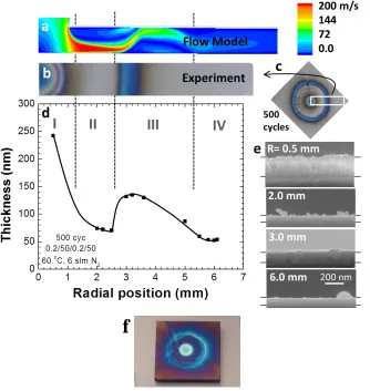
Figure 5.3. (a) Images for films deposited on silicon using different gap spacing and nitrogen gas flow rates. (b) Velocity contours (m/s) from CFD modeling of steady state N2 flow
through the deposition zone at relevant conditions. Using a sufficient gas flow rate, uniform radial flow is obtained for relatively small gap sizes, leading to uniform deposition. For larger gap sizes, gas can flow straight from the nozzle through the gap. The flow gradient creates a Bernoulli force that can pull ambient air and water vapor into the growth zone, leading to visible nonuniformity in the corresponding experimental deposition images. .... 120
Figure 5.4. (a) In loco ALD apparatus adjacent to a Volkswagen automobile. (b) Close-up image of the ALD head affixed to the rear side window glass, delivering 400 cycles of ALD coating to a local region on the window at 50 °C. (c) ALD-coated window removed from the car for ellipsometry analysis. The circled region corresponds to the ALD head mounting location. (d) Close-up image showing the semicircular ALD zone outlined by multicolored CVD growth. (e) Thickness versus number of ALD cycles measured by ellipsometry for ALD coatings on silicon fixed to the car window and on the window itself. The growth per cycle of the in loco ALD tool was 0.95-1.05 Å/cycle, corresponding to high growth rate of ~3 nm/min. ... 121
retaining its original copper color. (e) A modified delivery head was used to deposit spot coatings of ~5 mm diameter onto porous fiber substrates. (f) After localized coating (3 cycles, TMA/N2 = 200/100 s + H2O 10 s), a hydrophilic polyethylene terephthalate (PET)
fabric becomes hydrophobic in the coated region, repelling red-dyed liquid water. (g and h) The same in loco ALD treatment on a hydrophobic polypropylene fiber mat creates local hydrophilic regions that collect and hold red-dyed water droplets. ... 122
Figure 5.6. Schematics of different designs for the ALD delivery head tested in this study with close ups on the nozzle section, image of the nozzle section and images of samples after deposition of different ALD cycles. Silicon substrates were held in position using a low pressure region generated by the high gas speed based on Bernoulli’s principle. Orthogonal and oblique flow outlets were tested and images of silicon wafers from the orthogonal flow design are shown on the right. The ALD delivery head is operated in the a traditional temporal recipe scheme with nitrogen flowed continuously through the three leading tubes and alternating TMA and H2O pulses carried by nitrogen from the respective delivery lines.
... 124
turbulence; and IV, uniform radial flow. (f) A sample showing an alternate non–uniform coating pattern produced using the design in Figure 5.6. During coating, this sample was held in place only by the Bernoulli pressure and it vibrated noticeably during the run, likely
producing the visible wave–pattern in the deposited film. ... 125
Figure 5.8. The plot shows a linear relation between the film thickness measured using ellipsometry in Region IV (R=6 mm) shown in figure 5.7 versus number of ALD cycles suggesting growth in this zone follows a characteristic ALD growth mode with a growth per cycle of 0.95-1.05 Å/cycle. It was observed that the deposited film was ~10% thicker when the purge time was decreased from 50 to 20 sec indicating insufficient removal of excess reactants and byproducts at the lower purge time. The plot also shows ~5 nm of Al2O3 was
deposited after 300 TMA/N2 dose purges steps with no water doses indicating slight
diffusion of ambient moisture into the deposition zone... 126
Figure 5.9. Turbulence effect on growth at the nozzle outlet of the ALD delivery head. a) Contours of the turbulent kinetic energy (m2/s2) over the deposition surface from CFD modeling of steady state N2 flow. b) and c) Images of the films deposited with 600 ALD
Figure 5.10. Extent of CVD beyond the edge of the delivery head for various TMA exposure times per cycle. Longer exposure time produced more unreacted TMA leaving the growth zone, resulting in more CVD beyond the surface covered by the delivery head. ... 130
Figure 5.11. Drawings showing the positioning of ALD delivery heads on a) low curvature and b) high curvature surfaces. The head design with oblique outlet and ~8 cm2 flat
deposition area cannot contact closely high curvature surface where a design that covers much smaller area is needed like (c) an ALD “pen”. The proposed design (c), not to scale, is an orthogonal flow one with inverted vortex shape to avoid formation of stagnant points on the deposition surface. It also should cover low deposition area (≤ 0.5 cm2) to fit closely on
(b) highly curved and irregular surfaces. ... 132
Figure 6.1. Schematics of the spatial ALD setup. (a) Substrate going through the TMA and H2O reactant zones separated by N2 in a tool comprising 3 ALD cycles. (b) Linear
reciprocating motion of a substrate under a spatial ALD tool comprising X number of ALD cycles to achieve a total number of cycles equals to X multiplied by the number of
reciprocations. (c) Conceptual design of the spatial ALD showerhead where the gas flows through a gas manifold to get distributed to the respective channels and next through the nozzle arrays beneath these channels. ... 161
showerhead setup consisting of (c1) gas manifold tubes and (c2) gas channels leading to the outlet nozzle arrays. (c3) and (c4) are the bottom views of the (c1) gas manifold tubes and (c2) channels, respectively. ... 162
Figure 6.3. The CFD model and results for N2 flow through the TMA line. (a) CFD
geometry of the TMA manifold tube leading to the 5 TMA channels, each having 75 gas outlets (nozzles). (b) The total outlet flow rate through each channel for different inlet flow rates and channel diameters. The results for 1 slm at 1/4 in and 1/8 in channel diameters were plotted on a different scale (right) to clearly show the variation in uniformity. (c) Outlet gas velocity profile of different TMA channels from two separate CFD runs, one with 1/4 in channels and the second with 1/8 in channels. Both runs were done with 1 slm inlet flow rate to a 1/2 in manifold tube. (d) Compiled data for the COV in outlet velocity of several CFD runs using different manifold tube and channel diameters for various inlet gas flow rates. The COV was determined by dividing the standard deviation in velocity per channel by the average outlet velocity of this channel. The error bars represent the different COV values for the 5 channels for each CFD run... 163
Figure 6.4. Outlet gas velocity profiles for (a) the twelve channels of the main N2 line and (b)
the six channels of the water line at inlet flow rates of 9 and 3 slm respectively. Both modeling runs had manifold tubes featuring 1/4 in inlet and 1/8 in outlets, along with 1/4 in channels comprising 75 nozzles outlets of 0.5 mm diameter each. ... 164
different gap spaces between the nozzle and the fabric. The coated area turns hydrophilic and the extent of which was determined using red-dyed water. The coated area on the top surface of the fabric grew by increasing the gap spacing, however gas penetration through the fabric decreased significantly. ... 165
Figure 6.6. (a) 3D geometry of the CFD model to determine flow and species uniformity on the porous surface. The model has different flow inlets for the different nozzle arrays, a porous zone and pressure outlets. The inlet volume fractions of H2O and TMA were set to
0.05 at their respective nozzles. The flow rate through the N2 channels was set to 10 slm for
all the runs. (b-d) The contours of the volume fraction of N2 on the porous zone top plane at
different gap spacing and outlet gas flow rates as indicated in the figure. The red color indicates N2 zones, with volume fraction ~1, between the two reactant zones (blue color)
verifying that the suggested design specifics and process conditions prevents reactants from mixing. ... 166
Figure 6.7. Velocity contours through the nozzles, gap spacing and the porous zone. Results shown are for gap spacings of 0.4 and 1 mm, and flow rates of 3 and 5 slm. 1 m/s inlet velocity was used for the 3 slm run. The plane where these velocity contours were
Figure 6.8. Al2O3 coatings using the Spatial ALD process for porous substrates. (a) Images
of silicon strips placed on top of the PP web were used to determine the extent of ambient moisture diffusion into the deposition area. The process was run with no water flowing to the deposition zone for 100 ALD cycles, thus any film growth could be attributed to ambient moisture. The flow rates beside the images are for the flow through the main N2 line. (b)
Image of the PP fabric after being immersed in red-dyed water post-deposition of 100 ALD cycles using the spatial ALD process. (c) Comparing the change in water contact angle of the non-woven PP fabric against the number of ALD cycles produced using temporal and spatial ALD processes. The dose sequence (TMA/N2/H2O/N2) of the temporal ALD was
0.5/30/0.5/30 sec. The spatial ALD process was run at a substrate speed of ~5 m/min with N2
flow rates at the central showerhead of 15, 0.4 and 0.15 slm through the main N2 line, TMA
bubbler and H2O bubbler respectively. ... 168
Figure 7.1. Mass gain of samples treated with SVI at a) 2.5 Torr and b) 760 Torr as a
function of number of TMA cycles at various process temperature. ... 190
Figure 7.2. Comparison of mass gain for samples treated by SVI process with 60 cycles of TMA at 2.5 and 760 Torr for process temperature between 60 °C and 150 °C. ... 191
Figure 7.4. Consumption of C=O peak in FTIR spectra as function of temperature after 30 and 60 cycle SVI treatment at a) 2.5 Torr and b) 760 Torr. ... 193
Figure 7.5. Calculated diffusivity values of TMA molecules in N2 as a function of pressure
at 60, 90, 120 and 150 °C. ... 194
Figure 7.6. Optical images of samples masked during 30 cycle TMA exposure SVI
experiments at 60 °C at 2.5 Torr ((a) and (c)) and 760 Torr ((b) and (d)) under normal light ((a) and (b)) and UV illumination ((c) and (d)). ... 195
Figure 7.7. Schematic of hybrid materials formation through the fabric cross-section in the case of a) ideal masking, b) low resolution masking at low pressures, and c) good resolution masking at high pressures. ... 196
Figure 7.8. Effect of vapor infiltration temperature of TMA in PET and the post-deposition
heating on the formed hybrid material. (a) Ex situ FTIR spectra of the PET samples
infiltrated at 90 and 150 oC, as well as the sample infiltrated at 90 oC followed by a 24 hrs
heating at 150 oC in inert atmosphere. Images of the samples after infiltration at (b) 150 oC
and 90 oC are shown depicting a clear visual difference in color. Also images for the samples
treated at similar infiltration conditions but were heated for 24 hrs at 150 oC after infiltration
are shown in (d) and (e). ... 198
Measured vapor pressure vs temperature. During deposition, the DHP vessel was kept at ~68 °C. ... 222
Figure 8.2. Thermal ALD process characteristics for tin deposition using SnCl4 and DHP. (a)
Mass uptake per cycle for 3x multi-doses (3x SnCl4/ 3x DHP) at different reactor
temperatures between 130 and 210 oC. (b) Mass uptake per cycle against the total number of
dosed SnCl4 moles at 170 oC and 210 oC. The number of dosed DHP moles for each SnCl4
exposure is shown besides the data points on the plot. (c) Thin film growth against
processing time using three sequential doses of SnCl4 followed by three sequential doses of
DHP at 190 oC. The results in the figures confirm the self-saturation nature of the SnCl4/DHP
ALD process within the shown temperature window. ... 223
Figure 8.3. Analysis of the deposited tin metal thin film on silicon substrate using 1500 ALD cycles at a deposition temperature of 190 oC using a) ToF-SIMS and b) XPS depth profiles. The deposited metal was capped by titanium nitride (TiN) and titanium oxide (TiO2) layers to
prevent its oxidation on air exposure for the shown ex-situ analysis. ... 224
Figure 8.4. High resolution XPS spectra for (a) Sn 3d, (b) N 1s, (c) C 1s and (d) Cl 2p for the capped tin thin film, with TiO2 and TiN, deposited at 190 oC after 125 min of argon ions
sputtering. (e) Comparison of the chlorine content in the tin films deposited at 130 and 190
oC using high resolution XPS spectra for the Cl 2p of both films. Magnified Spectra (10X)
Figure 8.5. Cross-sectional SEM images at (a) low and (b) high magnifications for the capped tin thin film with TiO2 and TiN. The results confirmed the deposition of a conductive
layer of elemental Sn metal with a good thickness uniformity. The high magnification inset image in (b) was used to determine the Sn film thickness. ... 226
Figure 8.6. Working hypothesis of different reaction paths for the interaction of the DHP with a chlorine terminated surface. (1) Both tri-methyl silyl groups on the DHP strip off chlorine from the surface and leaves behind pyrazine molecule that desorbs later depending on the substrate temperature. (2) One chlorine atom reacts with each DHP molecule to form tri-methylsilyl chloride (TMS-Cl) and leaves a methyl terminated surface which gets
chlorinated again during the SnCl4 dose. ... 227
Figure 8.7. In Situ QMS data for the SnCl4/DHP ALD process. Analog scans for m/z range
20-240 during (a) SnCl4 and (b) DHP doses through their respective hold cells; the major
peaks are labelled. (c) Traces for selected m/z representing various reactant and product species during multiple sequential doses of the reactants. ... 228
Figure 8.8. In situ FTIR spectra for tin coatings on anodic aluminum oxide (AAO) deposited at 130 oC and 190 oC. The spectra were taken after different number of ALD cycles and were referenced to the spectrum of the bare AAO substrate. The exposure and purge sequences for the depositions are also shown on the plots. ... 229
Figure A1.1. Thickness of deposited (a) ZnO and (b) Al2O3 films on native oxide silicon
ellipsometry was used to determine the film thickness. Adding ozone dose to the typical DEZ/H2O and TMA/H2O processes has led to a significant change in ZnO growth but a
minor one for the Al2O3 deposition. ... 236
Figure A1.2. Mass uptake against ALD processing time for the two reactants (DEZ/H2O)
and 3 reactants (DEZ/H2O/O3) processes for ZnO deposition. As the dose time of ozone
increases, the average mass uptake decreases. Figure (b) is a close up of (a) and shows that the decrease in mass uptake for longer ozone dose times is due to a lower uptake during the DEZ dose. . ... 237
Figure A1.3. QMS analog scans during the doses of (a) DEZ, (b) H2O and (c) O3. Some
peaks of interest are ascribed to relevant species. The production of CO2, alcohols and
acetaldehyde suggests that ozone leads to a combustion like reaction on the surface even after a long water dose. . ... 238
Figure A1.4. In-situ FTIR differential spectra for the two reactants (a) (DEZ/H2O) and (b)
three reactants (DEZ/H2O/O3) ALD of ZnO. Each spectra was referenced to the one collected
from the previous dose and all the runs were done on AAO substrate at 110 oC. The spectra were collected after 5 ALD cycles of the same reactants sequence, either DEZ/H2O or
DEZ/H2O/O3. ... 239
Figure A1.5. High resolution XPS scans of O 1s for ZnO ALD on native oxide silicon using (a) DEZ/H2O, (b) DEZ/O3, and (c) DEZ/H2O/O3 processes. A clear difference in the oxygen
1
CHAPTER 1
1.1 Atomic Layer Deposition (ALD)
1.1.1 Process Overview
ALD is a vapor phase nano-coating process for oxide, nitride, sulfide and elemental materials deposition as well as growth of organic and hybrid organic-inorganic thin films. The process proceeds in a cyclic manner and depends on the occurrence of sequential self-limiting reactions on the surface of interest to deposit one atomic layer per deposition cycle. Consequently, the desired coating thickness is determined by the total number of the
deposition cycles. In a typical ALD process, the reactants pass over the substrate at distinct steps separated by a purging step to ensure the complete removal of one reactant before the introduction of the next one. This segregation ensures the occurrence of a series of self-limiting heterogeneous reactions on the substrate surface only, and that is how the thickness can be precisely controlled. On the other side, excess reactant exposure does not lead to extra growth due to the self-limiting nature of the occurring surface reactions, which allows for the deposition of very uniform and conformal thin films even on very high aspect ratio structures (e.g. ≥1:1000).1 Moreover, many of the ALD reactions are highly exothermic thus can occur
at low temperatures, as low as room temperature2 in some cases.
oxide deposition using tri-methyl aluminum (TMA) and water as the process reactants, as well as the surface reactions occurring during each reactant exposure.
Another common example of an ALD chemistry for metal oxides deposition is zinc oxide growth using diethyl zinc (DEZ) and water, and the involved surface reactions are 3
Overall Reaction: 𝑍𝑛(𝐶2𝐻5)2+ 𝐻2𝑂 → 𝑍𝑛𝑂 + 2𝐶2𝐻6
DEZ exposure: 𝑍𝑛𝑂𝐻∗+ 𝑍𝑛(𝐶2𝐻5)2→ 𝑍𝑛𝑂𝑍𝑛(𝐶2𝐻5)∗+ 𝐶2𝐻6
Water exposure: 𝑍𝑛 (𝐶2𝐻5)∗+ 𝐻
2𝑂 → 𝑍𝑛𝑂𝐻∗+ 𝐶2𝐻6
desorption rate is higher than their reaction rate. High growth per cycle, relative to the ALD window, can occur at high temperatures if the precursor started to decompose in the gas phase before chemisorbing on the surface which leads to multi-layer deposition of the undesired species.
1.1.2 ALD in Manufacturing
Atomic layer deposition (ALD) process has been used industrially since the early ‘80s. The process was initially used in the production of thin film electroluminescent (TFEL) displays in 19834, 5, primarily because of the process ability to produce very uniform thin coatings of zinc sulfide based films. About twenty years later, the semiconductor industry started to adopt the ALD process in depositing high-k dielectric materials for applications as gate oxides for metal-oxide semiconductor field effect transistors (MOSFET) 6, capacitor dielectrics in dynamic random access memories (DRAM) 7 and in forming gap dielectrics for
magnetic heads8. The main drive for such development was the ability of ALD to deposit ultra-thin uniform coatings over large wafer sizes with very high conformality on high aspect ratio structures, besides its unique ability to precisely control deposition thickness up to atomic level. Although currently these are the key industrial applications of ALD, it is anticipated to be used in multiple other processing steps in the manufacturing of the next generation logic and memory devices. The promising applications of the ALD process in the semiconductor industry is covered further in the introduction section of Chapter 8 of this dissertation.
techniques. However, eventually ALD proved to be the best choice whenever conformal thin films are required for complex 3D structures. Moreover, the very low deposition rate was mitigated by batch processing of large number of wafers, where up to 100 wafers of the 12” size can be coated per run. 9
In early 2011, Levitech revealed there continuous fast aluminum oxide ALD system for silicon solar cells passivation. The system allows for deposition rates up to ~1500 nm/hr and is based on the spatial ALD processing which is discussed later in this chapter. Shortly after that, Solay Tech announced a similar system with nearly similar deposition rate but with much lower footprint due to the wafer oscillation back and forth through the deposition region. Although these systems showed fast ALD depositions, they are still limited to planar non- flexible substrates.
the dry processing at low operating temperatures of the ALD process along with its other merits.
1.1.3 ALD Reactors
Many of the existing ALD reactors designs are inspired by chemical vapor deposition (CVD) counterparts but with more rigorous valve controls to allow for the required
sequencing of the reactants. In ALD reactors, ensuring enough reactants exposure to react with “all” of the available surface species is more important than ensuring reactants
homogeneity in the gas phase as is the case in the CVD process. Good ALD reactor will be one that allows efficient reactants utilization, the percent of dosed precursor that reacts with the substrate surface, and fast removal of the excess reactants away from the substrate to prevent any mixing between the reactants. ALD reactor designs are tailored for different substrates to optimize these parameters of dosing and purging according to the substrate needs and properties. Figure 1.3 summarizes various thermal ALD reactor designs available in the literature for different substrates. However, the gas delivery requirements are not the only factors that determine the reactor design criteria but also the sought throughput and deposited film properties such as uniformity, purity, continuity, morphology, functionality (e.g. conductivity) and processing requirements. For instance, in the semiconductor industry, the single wafer reactors (Figure 1.3a- 1-3) are used instead of the batch reactors whenever ALD process is followed or preceded by another process (e.g. PVD) where air-break needs to be avoided.
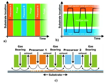
temporal ALD, where deposition occurs at different time intervals, for spatial ALD the dosing and purging steps are done at different positions10-12 as illustrated in Figure 1.4 and b.
The deposition rate, in case of the spatial ALD, is mainly controlled by how fast the half reactions will take place and the time required for moving the substrate between the different reaction zones to ensure excess reactants desorption from the substrate.
Spatial ALD allows for process throughputs tens to hundreds times higher than temporal ALD.16 The concept of separating reactants in space was introduced long time ago
by Suntola in the early patents of the ALD process.17 However, Levy et al.12 were the first to report an ALD saturation behavior for zinc oxide (ZnO) growth using the spatial ALD concept. The spatial design13, shown schematically in Figure 1.4c, has different precursor inlets separated by inert gas (named as gas bearing in Figure 1.4c) and exhaust channels, to prevent reactants mixing and removing reaction products. ALD can then be achieved by moving the coating head or the substrate back and forth. Later on, another spatial ALD reactor design was proposed by Poodt et al.14 They achieved a growth rate of 1.2 nm/s of aluminum oxide (Al2O3) deposition at atmospheric pressure in their “proof of concept”
ALD process, reactor designs and its prospective applications are discussed in the introduction section of chapter 6.
1.1.4 Atmospheric Pressure Atomic Layer Deposition (AP-ALD)
ALD process operations at medium to low vacuum in ultra-clean environment are essential for the semiconductor industry which rely on highly demanding process control in a batch processing manner. For other industries, such level of purity is not required, nonetheless process throughput and continuous mode of operation are critical. The ability to carry ALD processing at atmospheric pressure under ambient conditions will facilitate continuous mode operations and thus the process integration for in-line manufacturing in new industries beyond the semiconductor one. Moreover, working at ambient pressure will eliminate the time needed for reactor evacuation as well as pressure control and maintenance. For example, a roll-to-roll ALD process could be particularly useful to coat polymer webs for packaging or to modify fibrous materials surfaces for filtration or protective fabrics. More examples of the industries that can benefit of a high throughput continuous ALD process operating under ambient conditions are mentioned in the introduction sections of chapters 5, 6 and 7 of this dissertation.
of operating at very low pressures is the requirement of a turbo pump, which adds to the difficulty of the process scaling. On the other hand, most of ALD reactors nowadays are operating in medium vacuum (0.01-5 Torr) conditions under laminar viscous flow20 with Knudsen numbers lower than 0.01. Viscous flow reactors have better precursors’ utilization efficiency, besides being cheaper and easier to scale up. It was shown that the optimum pressure for the viscous flow ALD reactors is around ~1 Torr22 which represents a tradeoff between the gas advection and the diffusion of reactants and products through the inert gas. During the dosing step, pressure needs to be high enough so that the inert gas can carry enough amount of the precursor for surface saturation and also allows enough hitting (low gas mean free path) with the substrate surface for efficient precursor utilization. As for the purging step, low pressure is favored, since gases diffusivities are inversely proportional with pressure. Low diffusivity, under high pressure, can get the excess precursor or reaction products to stay on the surface even under long purge intervals leading to non-uniform ALD layers. The operating pressure in viscous flow reactor is thus determined based on these two competing effects of dosing and purging requirements.
The gas flow through an ALD reactor at atmospheric pressure will also be under viscous regime, except that higher amounts of precursor can be delivered relative to medium vacuum conditions and that the gas mean free path will be much lower (more surface
slower because of its inverse relation with the reactor pressure. These two factors will impose strict purge requirements on the ALD process operating under atmospheric pressure unless counteracted by other factors to speed up the species diffusion at high pressure. A large increase in purge time at atmospheric pressure operations should be avoided because it will lead to a large drop in the overall process throughput. Chapters 3 and 4 of this dissertation discuss ways for maintaining low purge time requirements for operations at atmospheric pressure and show that ALD can be carried out efficiently at high pressure with careful control of gas flow and reactor design.
1.1.5 Sequential Vapor Infiltration (SVI)
The vapor infiltration concept is based on allowing reactive spices in the gas phase to infuse and react in a solid substrate that has abundance of active sites, either on its surface or bulk, as is the case with many polymers. Vapor infiltration can be thought of as a
sub-category of ALD but with much longer exposures and purges to cover the very high surface area of the targeted substrates. This is a diffusion controlled process where reactants
polymers26, 27, nano-patterning for advanced lithography processes28, 29 and surface energy modification30.
The sequential vapor infiltration technique used in this dissertation proceeds through dosing of a metal organic precursor (e.g. TMA, DEZ) but instead of directly purging out the reactant, it is held in the reactor chamber for extended time to allow for its diffusion through the substrate. To ensure high reactant concentration in the gas phase and to remove formed byproducts, the reactor chamber gets purged out and new fresh dose and hold of the same reactant occurs. This sequential dosing, holding and purging of the same reactant occurs for as many times as need to ensure the whole substrate modification and then followed by an extended purge step up to tens of minutes. Following the extended purge, the same dose, hold and purge steps can be repeated for a co-reactant or in some cases the infiltration of the organometallic precursor only is sufficient.
More details of the vapor infiltration processes and their processing techniques can be found in the introduction section of chapter 7.
1.2 Metals and Metal Oxides ALD
1.2.1 Metal Oxides Deposition: Water vs Ozone as a Co-reactant
Metal oxides ALD is the most widely studied and applied class of materials relative to nitrides, sulfides, carbides or elemental ALD. By far the three most commonly deposited oxides by ALD are Al2O3, ZnO and TiO2 due to the high reactivity of their precursors which
dissertation, Al2O3 was deposited using TMA/ H2O and TMA/O3 chemistries, while
DEZ/H2O was used to deposit ZnO and titanium dioxide (TiO2) was deposited using titanium
chloride (TiCl4) and titanium tetra-isopropoxide (TTIP).
The common oxygen sources used to deposit metal oxides by thermal ALD processes are water and ozone, whereas oxygen, hydrogen peroxide and metal alkoxides were used in few cases. While water based ALD chemistry proceeds mostly in ligand exchange
mechanism as shown earlier for the TMA/H2O ALD process32, ozone chemistry are more
like combustion reactions with ligand fragmentation occurring. Although the details of the ozone based reactions are not widely explored in the literature, the overall reaction with TMA can be written as31,
2Al(CH3)3(g) + nO3(g) → 2Al2O3(s) + COx(g) + H2O(g) + possible other products
A review of the TMA/O3 ALD reaction mechanism studies in the literature is available in the
introduction section of chapter 4 of this dissertation.
Ozone has much higher reactivity than water and is commonly used with stable precursors that typically do not react with water like β-diketonates precursors (e.g. Zr(thd)4).33, 34 Recently, ozone is being investigated to replace water for standard ALD
chemistry that proceeds well with water, even the established TMA/H2O process, since it
high-k dielectric applications in the semiconductor industry.35, 36 On the other side, there are cases where water is favored over ozone as the example of HfO2 deposition as a gate oxide
since ozone high reactivity leads to unacceptable oxidation of the silicon substrate. Also, for lead oxide deposition, there are situations where water is preferred to prevent the formation of volatile and toxic higher oxidized species.37 In addition, at high temperatures (i.e. ≥ 300
oC), ozone tends to decompose quickly to non-reactive oxygen which will require extended
exposure times and suitable reactor design for fast gas delivery. It has also been shown in several studies that metal oxides deposited using ozone had high level of contamination, mainly carbonate, probably due to the formed carbon oxides products.38, 39 Out of all of these, the major limitation of using ozone in metal oxides ALD is its tendency to recombine on certain surfaces which leads to poor thickness uniformity and conformality.40-42
Another interesting ALD chemistry for metal oxides deposition is through using two organometallic precursors. The hydroxyl groups in the metal alkoxides are the source of oxygen in this case.43, 44 Al2O3 and TiO2 were deposited successfully using aluminum
chloride/aluminum alkoxide43 and titanium chloride/titanium tetra-isopropoxide45, 46 respectively. The use of two organometallic precursors helps in attaining oxide free interfaces.43 In this dissertation, the TiCl
4/TTIP chemistry was used to form capping layers
on deposited elemental tin films to prevent the metal oxidation on air exposure for further ex-situ analysis as shown in chapter 8.
1.2.2 Metals Deposition by Thermal ALD: Reducing agents
work-function materials where uniform nucleation and ultra-thin layer growth can be problematic. Large part of the lack of developed processes for metals deposition is the absence of a universal reaction mechanism and the lack of fundamental understanding of precursor adsorption on metal surfaces with no reaction sites for the cyclic ALD process to occur. Moreover for thermal ALD processes, the absence of a general co-reactant
(counterpart to water in metal oxides ALD) with high reduction ability lead to the use of plasma based processes to generate high energy radicals. Hydrogen radicals were able to deposit many metals using plasma enhanced ALD processes like nickel47, cobalt48, iridium49, palladium50, and even high electropositive metals like aluminum51, titanium52 and tantalum52. However, plasma based processes are not straight forward and have their complications like damage to delicate substrates, mass transport limitations which leads to a poor thickness conformality in high aspect ratio structures due to the radicals recombination, and the formation of corrosive gases (e.g. HCl, HF) in case of using the hydrogen radicals with halogen based precursors.
For metals deposition using thermal ALD, it has been hard to find an effective reducing agent. Tungsten and Molybdenum deposition processes are the most successful ones that follow the exchange-type reactions of an ALD process, where silanes53, 54 were
used to reduce the metal halides precursors. The tungsten deposition process from tungsten hexa-fluoride (WF6) and di-silane (Si2H6) has wide temperature window (140-300 oC) and
tungsten films and had a narrower temperature window (90-120 oC).57 Vapors of zinc metal were also used to reduce molybdenum pentachloride (MoCl5) to the metallic state58, as well
as copper(I) chloride (CuCl) to copper59. Away from the difficulty of dosing vapors of a metal, the deposited films had high level of zinc contamination and the processes only occurred at very high temperatures.60 The other successful thermal ALD processes for growing metals are the one employing oxygen to deposit noble metals such as ruthenium61, platinum62, palladium63, and iridium64. Nevertheless, this is more of a combustion like
chemistry than a reduction one where the oxygen pulse oxidizes the metal surface which then reacts with the ligands of the noble metals precursors. The process is well studied and
understood but is not universal and only limited to few noble metals.65 Finally, due to the lack of a generic mechanism for ALD of metals, a three step process was used in some cases where the metal oxide was deposited first and then reduced through annealing in hydrogen atmosphere.66 A more comprehensive review of the studied ALD processes for metals deposition can be found in [67].
Pure hydrogen gas was sought to be the generic reducing agent for metals deposition by thermal ALD processes, but only worked in very limited cases owing to its low reactivity. At temperatures ≥250 oC, hydrogen was able to reduce amidinate precursors to deposit some
2-window (120-240 oC) at a growth rate of ~0.06 nm/cyc and with minimal level of contaminants.70 Deposition mechanisms are not clear yet and no in-situ characterizations
were done so far, also it was not shown if these reducing agents will work for other metal halide precursors to be the pursued universal ALD reducing agent.
1.3 Overview of the Key Advances in ALD Presented in this Dissertation
ALD can be considered a platform technology where many applications and products can be based upon. The technological key strength, beyond its ability to deposit ultra-thin very uniform and conformal coatings, is more about the new functionality and properties that these thin films add to the substrate by adding layers of molecules on top of its surface. Even though the process has shown promising potential to modify, improve, or create new
This dissertation focuses on overcoming the process development gap of ALD
technology for different applications while maintaining or improving the process throughput. This was achieved through understanding the effects of the different process parameters and tailoring them to improve the process outcome, proposing and testing prototypes of new ALD tool designs, and developing new chemistry for novel materials and understanding the underlying surface reaction mechanisms.
In chapters 3 and 4, the effects of the deposition pressure on the ALD process parameters and the deposited Al2O3 and ZnO thin films properties were investigated. The
findings in these chapters help in the development of ALD processes operating under atmospheric pressure and open to air conditions at low temperatures.
In chapter 3, the processes of Al2O3 and ZnO ALD using TMA/H2O and DEZ/H2O
species diffusion before being purged out by the bulk gas flow, thus decreasing the required purge time. The reported understanding of the favorable effect of the gas velocity during the purge step at high pressure and low temperature operations helps in achieving higher process throughputs without compromising the quality of the deposited thin films. This work was published as M.M. Mousa, et. al., J. Vac. Sci. Technol. A (2012) 30, 01A155.
In chapter 4, the use of ozone (O3) as the oxygen source instead of H2O for Al2O3
ALD was investigated to determine the effect of the new chemistry on the process parameters and deposited films properties at high pressure. The GPC was higher for depositions at high pressure, relative to 2 Torr, and decreased with increasing the gas velocity during the purge step on a similar trend to that of the water based chemistry. However, the required gas velocity was about 1/3 of that for the water based process to achieve GPC and thickness uniformity comparable to those of the depositions carried at 2 Torr. The difference in gas velocity requirements was attributed to the higher desorption rate of O3 relative to water. It
deposition temperatures where higher carbon content is expected. The ToF-SIMS data confirmed the higher carbon contamination level, both at low and high pressure operations. This chapter in short shows that although using ozone to deposit Al2O3 at atmospheric
pressure operations leads to shorter purge time requirement relative to the water based process, care need to be taken for the higher dose time needed and the lower film purity especially for low temperature operations. This work was published as M.M. Mousa, et. al., Langmuir (2014) 30, 3741.
In chapters 5 and 6, new high throughput ALD reactors are introduced to extend the process capabilities for in loco coatings on huge substrates and for fast coatings on porous substrates aimed for applications in textiles and batteries industries.
The ALD delivery head tool is presented in chapter 5, which allows for in loco
coatings on macroscale objects, too large to fit in currently available ALD reactors. The tool was used to coat part of an automobile window parked outdoors and showed that the
characteristic features of the ALD process can be applied on objects at their native locations under ambient conditions in an open to air environment. High deposition rates of Al2O3 up to
locations. This work was published as M.M. Mousa, et. al., ACS Appl. Mater. Interfaces (2015) 7, 19523.
In chapter 6, a new spatial ALD reactor design for coating porous substrates is
explained. Thin films of different materials deposited on fabrics and mesoporous scaffolds by ALD processes in lab scale were shown to have numerous applications in textiles, batteries and solar cells industries. Yet, there is no continuous ALD process to date that can allow for high deposition rates on such porous materials. The chapter discusses the design challenges for developing a spatial ALD tool for porous materials as well as all the gas flow dynamics models used to determine the design specifics and the process parameters. A prototype of the new design is shown, as well as the results of coating a high surface area polypropylene fabric. The preliminary results showed that it took the continuous spatial roll-to-roll ALD tool about 100 sec to deposit 5 nm of Al2O3 on ~ 1 m2 of the fabric surface area, which is a
very high area to coat in such short time. The development of such a high throughput tool will speed up the ALD process adoption by the textiles and batteries industries.
gravimetric measurements, was found to be higher at low process pressure and temperatures. As the temperature increased, the pressure effect on the polymer modification became insignificant. These results were explained using simple models showing the difference in species diffusion rates within the reactor, through the polymer matrix and within the fibers at different process pressures. Also, the FT-IR spectra of the samples at different deposition conditions agreed well with the model predictions. Understanding the effect of process parameters on the formed hybrid material, especially with the improved patterning ability, will help in the scaling up of the process for unique applications in flexible electronics and protective identification. This work was published as H.I. Akyildiz, M.M. Mousa, et. al., J. Appl. Phys. (2015) 117, 045301, where the first two authors had equal level of contribution.
Finally, chapter 8 shows another level of the ALD process development where a new chemistry is being investigated for depositing a novel material, tin metal (Sn) thin films. This is the first time in literature to deposit tin metal using an ALD process where tin(IV) chloride and 1,4-Bis(trimethylsilyl)-1,4-dihydropyrazine (in short DHP) were used as a precursor and a reducing agent co-reactant respectively. The quartz crystal microbalance (QCM) analysis showed an ALD process window between ~ 170- 210 oC. The mass uptake values showed a self-saturation behavior for both reactants with an average uptake per cycle of ~225
ng/cm2/cyc within the ALD window. The self-saturation was also confirmed using mass spectrometry measurements to track the change in signature peaks of the reactants during multiple sequential doses of SnCl4 and DHP. SEM imaging showed that deposited metal
Figure 1.1. Aluminum oxide cyclic deposition using ALD process starting with hydroxyl terminated surface. (1 and 2) Methyl terminated surface is formed after Tri-methyl Aluminum (TMA) dosing and purging then (3 and 4) turns to hydroxyl
terminated surface again, with formation of Al2O3 atomic layer, after dosing and purging
Figure 1.3. Various designs of ALD reactors for different substrate types. A) Planar substrates involve flow of the gases over the surface either for a-1,2,3) single wafer31 or a-4) multiple wafers9. B) Particles of different sizes coated in b-1) fluidized bed
reactor72-74 and b-2) rotary drum reactor75,76. C) ALD reactors for polymer webs and other flexible substrates were illustrated by c-1) Lotus Applied Technology77 and c-2)
1.4 References
(1) Gordon, R. g.; Hausmann, D.; Kim, E.; Shepard, J. A Kinetic Model for Step Coverage by Atomic Layer Deposition in Narrow Holes or Trenches. Chem. Vap. Depos. 2003, 9 (2), 73–78.
(2) Groner, M. D.; Fabreguette, F. H.; Elam, J. W.; George, S. M. Low-Temperature Al2O3 Atomic Layer Deposition. Chem. Mater. 2004, 16 (4), 639–645.
(3) Elam, J. W.; Sechrist, Z. A.; George, S. M. ZnO/Al2O3 Nanolaminates Fabricated by Atomic Layer Deposition: Growth and Surface Roughness Measurements. Thin Solid Films
2002, 414 (1), 43–55.
(4) Suntola, T. Atomic Layer Epitaxy. Mater. Sci. Rep. 1989, 4 (5), 261–312.
(5) Suntola, T.; Hyvarinen, J. Atomic Layer Epitaxy. Annu. Rev. Mater. Sci. 1985, 15 (1), 177–195.
(6) Bohr, M. T.; Chau, R. S.; Ghani, T.; Mistry, K. The High-K Solution. IEEE Spectr. 2007,
44 (10), 29–35.
(7) Kim, K. N. Technology for Sub-50nm DRAM and NAND Flash Manufacturing. Symp VLSI Techn 2000, 10.
(8) Ritala, M.; Niinistö, J. Industrial Applications of Atomic Layer Deposition. ECS Trans.
2009, 25 (8), 641–652.
(9) Granneman, E.; Fischer, P.; Pierreux, D.; Terhorst, H.; Zagwijn, P. Batch ALD: Characteristics, Comparison with Single Wafer ALD, and Examples. Surf. Coat. Technol.
2007, 201 (22–23), 8899–8907.
(10) Charton, C.; Schiller, N.; Fahland, M.; Hollaender, A.; Wedel, A.; Noller, K.
Development of High Barrier Films on Flexible Polymer Substrates. Thin Solid Films 2006,
502 (1-2), 99–103.
(11) Hoppe, H.; Sariciftci, N. S. Organic Solar Cells: An Overview. J. Mater. Res. 2004, 19
(7), 1924–1945.
(13) Mahltig, B.; Haufe, H.; Boettcher, H. Functionalisation of Textiles by Inorganic Sol-Gel Coatings. J. Mater. Chem. 2005, 15 (41), 4385–4398.
(14) Jur, J. S.; Sweet, W. J.; Oldham, C. J.; Parsons, G. N. Atomic Layer Deposition of Conductive Coatings on Cotton, Paper, and Synthetic Fibers: Conductivity Analysis and Functional Chemical Sensing Using “All-Fiber” Capacitors. Adv. Funct. Mater. 2011, 21
(11), 1993–2002.
(15) Hyde, G. K.; Park, K. J.; Stewart, S. M.; Hinestroza, J. P.; Parsons, G. N. Atomic Layer Deposition of Conformal Inorganic Nanoscale Coatings on Three-Dimensional Natural Fiber Systems: Effect of Surface Topology on Film Growth Characteristics. Langmuir 2007, 23
(19), 9844–9849.
(16) Poodt, P.; Lankhorst, A.; Roozeboom, F.; Spee, K.; Maas, D.; Vermeer, A. High-Speed Spatial Atomic-Layer Deposition of Aluminum Oxide Layers for Solar Cell Passivation. Adv. Mater. 2010, 22 (32), 3564–3567.
(17) Suntola, T. S.; Pakkala, A. J.; Lindfors, S. G. Apparatus for Performing Growth of Compound Thin Films. US4389973 A, June 28, 1983.
(18) Ott, A. W.; Klaus, J. W.; Johnson, J. M.; George, S. M. Al3O3 Thin Film Growth on Si(100) Using Binary Reaction Sequence Chemistry. Thin Solid Films 1997, 292 (1–2), 135– 144.
(19) Sneh, O.; Wise, M. L.; Ott, A. W.; Okada, L. A.; George, S. M. Atomic Layer Growth of SiO2 on Si(100) Using SiCl4 and H2O in a Binary Reaction Sequence. Surf. Sci. 1995,
334 (1–3), 135–152.
(20) Elam, J. W.; Groner, M. D.; George, S. M. Viscous Flow Reactor with Quartz Crystal Microbalance for Thin Film Growth by Atomic Layer Deposition. Rev. Sci. Instrum. 2002,
73 (8), 2981–2987.
(21) Nishizawa, J.; Abe, H.; Kurabayashi, T. Molecular Layer Epitaxy. J. Electrochem. Soc.
1985, 132 (5), 1197–1200.
(22) George, S. M. Atomic Layer Deposition: An Overview. Chem. Rev. Wash. DC U. S.
(23) Peng, Q.; Tseng, Y.-C.; Darling, S. B.; Elam, J. W. A Route to Nanoscopic Materials via Sequential Infiltration Synthesis on Block Copolymer Templates. ACS Nano 2011, 5 (6), 4600–4606.
(24) Lee, S.-M.; Pippel, E.; Gösele, U.; Dresbach, C.; Qin, Y.; Chandran, C. V.; Bräuniger, T.; Hause, G.; Knez, M. Greatly Increased Toughness of Infiltrated Spider Silk. Science
2009, 324 (5926), 488–492.
(25) Gong, B.; Peng, Q.; Jur, J. S.; Devine, C. K.; Lee, K.; Parsons, G. N. Sequential Vapor Infiltration of Metal Oxides into Sacrificial Polyester Fibers: Shape Replication and
Controlled Porosity of Microporous/Mesoporous Oxide Monoliths. Chem. Mater. 2011, 23
(15), 3476–3485.
(26) Lee, S.-M.; Pippel, E.; Moutanabbir, O.; Gunkel, I.; Thurn-Albrecht, T.; Knez, M. Improved Mechanical Stability of Dried Collagen Membrane after Metal Infiltration. ACS Appl. Mater. Interfaces 2010, 2 (8), 2436–2441.
(27) Gregorczyk, K. E.; Pickup, D. F.; Sanz, M. G.; Irakulis, I. A.; Rogero, C.; Knez, M. Tuning the Tensile Strength of Cellulose through Vapor-Phase Metalation. Chem. Mater.
2015, 27 (1), 181–188.
(28) Tseng, Y.-C.; Peng, Q.; Ocola, L. E.; Czaplewski, D. A.; Elam, J. W.; Darling, S. B. Enhanced Polymeric Lithography Resists via Sequential Infiltration Synthesis. J. Mater. Chem. 2011, 21 (32), 11722–11725.
(29) Kamcev, J.; Germack, D. S.; Nykypanchuk, D.; Grubbs, R. B.; Nam, C.-Y.; Black, C. T. Chemically Enhancing Block Copolymers for Block-Selective Synthesis of Self-Assembled Metal Oxide Nanostructures. ACS Nano 2013, 7 (1), 339–346.
(30) Gong, B.; Spagnola, J. C.; Parsons, G. N. Hydrophilic Mechanical Buffer Layers and Stable Hydrophilic Finishes on Polydimethylsiloxane Using Combined Sequential Vapor Infiltration and Atomic/molecular Layer Deposition. J. Vac. Sci. Technol. A 2012, 30 (1), 01A156.
(31) Ritala, M.; Niinistö, J. Chapter 4. Atomic Layer Deposition. In Chemical Vapour
(32) Rahtu, A.; Alaranta, T.; Ritala, M. In Situ Quartz Crystal Microbalance and Quadrupole Mass Spectrometry Studies of Atomic Layer Deposition of Aluminum Oxide from
Trimethylaluminum and Water. Langmuir 2001, 17 (21), 6506–6509.
(33) Putkonen, M.; Niinistö, L. Zirconia Thin Films by Atomic Layer Epitaxy. A
Comparative Study on the Use of Novel Precursors with Ozone. J. Mater. Chem. 2001, 11
(12), 3141–3147.
(34) Nieminen, M.; Putkonen, M.; Niinistö, L. Formation and Stability of Lanthanum Oxide Thin Films Deposited from β-Diketonate Precursor. Appl. Surf. Sci. 2001, 174 (2), 155–166. (35) Kim, S. K.; Hwang, C. S. Atomic-Layer-Deposited Al2O3 Thin Films with Thin SiO2 Layers Grown by in Situ O3 Oxidation. J. Appl. Phys. 2004, 96 (4), 2323–2329.
(36) Kim, J. B.; Kwon, D. R.; Chakrabarti, K.; Lee, C.; Oh, K. Y.; Lee, J. H. Improvement in Al[sub 2]O[sub 3] Dielectric Behavior by Using Ozone as an Oxidant for the Atomic Layer Deposition Technique. J. Appl. Phys. 2002, 92 (11), 6739.
(37) Hoffmann-Eifert, S.; Watanabe, T. FeRAM. In Atomic Layer Deposition for Semiconductors; Hwang, C. S., Ed.; Springer US, 2014; pp 149–171.
(38) Kosola, A.; Putkonen, M.; Johansson, L.-S.; Niinistö, L. Effect of Annealing in
Processing of Strontium Titanate Thin Films by ALD. Appl. Surf. Sci. 2003, 211 (1–4), 102– 112.
(39) Goldstein, D. N.; McCormick, J. A.; George, S. M. Al2O3 Atomic Layer Deposition with Trimethylaluminum and Ozone Studied by in Situ Transmission FTIR Spectroscopy and Quadrupole Mass Spectrometry. J. Phys. Chem. C 2008, 112 (49), 19530–19539.
(40) Nilsen, O.; Fjellvåg, H.; Kjekshus, A. Growth of Manganese Oxide Thin Films by Atomic Layer Deposition. Thin Solid Films 2003, 444 (1–2), 44–51.
(41) Klepper, K. B.; Nilsen, O.; Fjellvåg, H. Growth of Thin Films of Co3O4 by Atomic Layer Deposition. Thin Solid Films 2007, 515 (20–21), 7772–7781.
(43) Ritala, M.; Kukli, K.; Rahtu, A.; Räisänen, P. I.; Leskelä, M.; Sajavaara, T.; Keinonen, J. Atomic Layer Deposition of Oxide Thin Films with Metal Alkoxides as Oxygen Sources.
Science 2000, 288 (5464), 319–321.
(44) Mui, C.; Musgrave, C. B. Atomic Layer Deposition of HfO2 Using Alkoxides as Precursors. J. Phys. Chem. B 2004, 108 (39), 15150–15164.
(45) Chaukulkar, R. P.; Agarwal, S. Atomic Layer Deposition of Titanium Dioxide Using Titanium Tetrachloride and Titanium Tetraisopropoxide as Precursors. J. Vac. Sci. Technol. A 2013, 31 (3), 031509.
(46) Anderson, V. R.; Cavanagh, A. S.; Abdulagatov, A. I.; Gibbs, Z. M.; George, S. M. Waterless TiO2 Atomic Layer Deposition Using Titanium Tetrachloride and Titanium Tetraisopropoxide. J. Vac. Sci. Technol. A 2014, 32 (1), 01A114.
(47) Lee, H.-B.-R.; Bang, S.-H.; Kim, W.-H.; Gu, G. H.; Lee, Y. K.; Chung, T.-M.; Kim, C. G.; Park, C. G.; Kim, H. Plasma-Enhanced Atomic Layer Deposition of Ni. Jpn. J. Appl. Phys. 2010, 49 (5S2), 05FA11.
(48) Yoon, J.; Lee, H.-B.-R.; Kim, D.; Cheon, T.; Kim, S.-H.; Kim, H. Atomic Layer Deposition of Co Using N2/H2 Plasma as a Reactant. J. Electrochem. Soc. 2011, 158 (11), H1179–H1182.
(49) Song, S. I.; Lee, J. H.; Choi, B. H.; Lee, H. K.; Shin, D. C.; Lee, J. W. Hydrogen-Plasma-Assisted Hybrid Atomic Layer Deposition of Ir Thin Film as Novel Cu Diffusion Barrier. Surf. Coat. Technol. 2012, 211, 14–17.
(50) Eyck, G. A. Ten; Senkevich, J. J.; Tang, F.; Liu, D.; Pimanpang, S.; Karaback, T.; Wang, G.-C.; Lu, T.-M.; Jezewski, C.; Lanford, W. A. Plasma-Assisted Atomic Layer Deposition of Palladium. Chem. Vap. Depos. 2005, 11 (1), 60–66.
(51) Lee, Y. J.; Kang, S.-W. Atomic Layer Deposition of Aluminum Thin Films Using an Alternating Supply of Trimethylaluminum and a Hydrogen Plasma. Electrochem. Solid-State Lett. 2002, 5 (10), C91–C93.