Optimized Multisegment Sliding Mode
Controller for 3 Phase I. M. Drive
Rajan T. Patel1, Jatin G. Patel2, Dr. Ami T. Patel3
P.G. Student, Department of Electrical Engineering, MGITER Engineering College, Navsari, Gujarat, India1
Assistant Professor, Department of Electrical Engineering, MGITER Engineering College, Navsari, Gujarat, India2
Assistant Professor, Department of Electrical Engineering, Government Engineering College, Bharuch, Gujarat, India3
ABSTRACT: Induction motors have been widely used in the industry for a long time due to its easy build, high robustness and generally satisfactory efficient. Multi-segment sliding mode control method is more suitable than sliding mode control method. Multi-segment sliding mode control method consists a four segment but sliding mode control used only one segment for different arrangement. MSSMC method is very effective to control the system because it requires the many advantages like insensitivity to parameter variations, external disturbance rejection, and fast dynamic responses. The comparison will be carried out between MSSMC simulation results and literature results. MSSMC techniques have been applied an induction motor, or compare performance under different loading condition. The disadvantage of multi-segment sliding mode controller is chattering effect. To overcome this above problem, different smart control techniques like ANN, FLC, and GA have been developed. The ANN based MSSMC, Fuzzy based MSSMC and GA based MSSMC is used to reduce the chattering effect for different loading condition. But, FMSSMC and ANN based MSSMC gives better performance only for fixed parameters. So, ANN based MSSMC design is replaced by Genetic Algorithm based MSSMC to overcome the limitation of the same.
KEYWORDS:Incremental motion control, position control, velocity control, sliding mode control, induction motor. I. INTRODUCTION
In past year, dc motors have been widely used in industry. The Mechanical commutators and brush assembly to make dc motor much more expensive as compare to ac motor. The mechanical commutators are produced undesirable spark, which are not allowed in some applications. This is the disadvantages of D.C. motor. The solution of this problem to use ac drives. In ac drives also include two motors like synchronous motor and induction motor. I.M has been widely used in the industry. Here, several advantages of I.M consist like simple construction, reliable and relatively low cost, high efficiency and high robustness. The various application of I.M in industry like paper and textile mills, machine tools, robotics, heat pumps, rolling mills, etc. [8]
Various control techniques of I.M drives are scalar control, vector or field-oriented control, direct torque control, and flux oriented control. It is difficult to construct because of the parameter variations due to the uncertain external disturbances, and this performance PI-type control method are not robust to control the variations of external disturbances, parameters variation during operation. [12]
Multi-segment sliding mode control method is more suitable than the Sliding mode control method for the incremental motion control of I.M. It is also very interesting to know that, here, as we are using the MS-SMC not the SMC so the reaching phase of the SMC does not exist over here, because the system dynamics are itself in a sliding mode at the start. The robustness of the controlled system can be assured from start to finish. MS-SMC techniques have been applied an I.M., or compare the performance under different loading condition. The chattering effect is the main disadvantage of multi-segment sliding mode control. This chattering can be eliminated by using smart control techniques like fuzzy logic controller, artificial neural network and Genetic algorithm. The study of Genetic algorithm based MS-SMC for velocity and position control of I.M. is presented. [17]
The design of FMS-SMC and ANN based MS-SMC provide reliable performance only for fixed parameter. Thus, study of Genetic algorithm is presented. GA works on coding of the parameter to be optimized and gives global optimum solution. [17]
II. RELATED WORK
Fundamentals of 3 phase induction motor servo drive:
Anup Kumar Singh, Nallapaneni Manoj Kumar, Swapnajit Pattnaik, K. Vinay Reddy had discussed For controlling the input current and to increase the input power factor, Generalized Scalar Pulse Width Modulation (GSPWM) technique is used which also has reduced the tracking error as well as the losses. And to control the output voltage, SVPWM technique is used. It has also been shown that the stator current is approximately sinusoidal which contains fewer harmonics as desired. V/F controlling is being done efficiently. Also, the input power factor obtained with the proposed technique comes out to be almost unity which also shows the effectiveness of the proposed technique [8].
Mathematical modelling of 3-phase Induction motor:
Muhammad Junaid Asif et all Work presented here is a dynamic model of an induction motor. Dynamic modeling plays an important role for studying the transient analysis of motor because static modeling cannot be used to analyze the steady state behavior of the machine. Three phase voltage is given to the motor. Simulation is done by using the Simulink/MATLAB because it gives more efficient results and involves small simulation time as compared to other computer software. In this paper we studied the torque vs. speed behavior of the machine. For this purpose we use the Clarkes transformation to convert the three phase quantities in to two phase quantities. The output taken from the systems are in the form of α and β components of both rotor and stator currents, electrical torque and armature power of the induction machine [10].
Different Techniques for speed control of 3-phase Induction Motor:
Muhammad Asad, Muhammad Arif This presented the FPI controller and its implementation for the controlling speed of induction motor (IM). The results of FPI are compared with the classical PI controller which shows the improvement in the response in terms of speed of induction motor. Results can be further improved by Optimizing rule matrix with different possible optimization techniques [12].
Concepts of sliding mode control for 3-phase Induction Motor:
HUANG Peng,HUANG Lei,MIAO Changyun introduced a multi-segment sliding mode control method for a permanent magnet synchronous motor (PMSM). To solve the problem of parameter variations and load disturbance in servo control system, the method to design sliding mode controller was analyzed thoroughly. Multisegment sliding mode controller was proposed with the ability to improve robustness of the system effectively. Experimental results show that the system with multi-segment sliding mode controller has good robustness and fast response [14].
Different Methods for parameter tuning for MS-SMC:
W.-D. Chou, F.-J. Lin and K.-K. Shyu presented An incremental motion control problem, specified by a trapezoidal speed command profile using multi-segment sliding mode control (MSSMC), is proposed to control an induction motor (IM) servo drive. Since the control gains in the MSSMC are fixed, chattering responses occur due to large external load disturbances. Therefore, a real-time genetic algorithm (GA) is developed to tune the control gains online. A field-oriented control IM servo drive is implemented an4 each segment of the multi-segment switching surface is designed so as to match the corresponding part of the trapezoidal speed command profile. [16]
III.INCREMENTAL MOTION CONTROL OF AN INDUCTION MOTOR [4]
The incremental motion is to move an object at rest at time
t
0 to a fixed desired position θd at time td , and then stop it. The control process is subjected to the desired velocity and acceleration. So the incremental motion control is performed under velocity control in obedience to a desired velocity profile, whereas stopping is done by position control mode. One first has to select a velocity profile which rapidly changes the load position in discrete step. The velocity profile (i.e., the motor and load angular velocity as a function of time) should satisfy the motion constraints of the system. The velocity and acceleration limitations are generally taken into consideration for the determination of velocity profile.To satisfy the velocity and acceleration limitations, a trapezoidal velocity profile is usually used. The trapezoidal velocity profile is shown in Fig.1. It can be seen that the trapezoidal velocity profile is composed of three parts: acceleration (from time t0 to
t1), run (from time t1 to t2), and deceleration (from time t2 to t3).
Unfortunately, it is not easy to control the motor motion in accordance with the given trapezoidal profile. Because of the system dynamics are subjected to unknown load perturbations. Therefore, the object here is to design a multi-segment sliding mode controller according to the trapezoidal velocity profile shown in Fig.1,
Fig.1 Trapezoidal velocity profile for incremental motion
(1) Acceleration segment (acceleration=θd1); (2) run segment (velocity=θd); and (3) deceleration segment (deceleration=θd2), so that the motor rotates in obedience to the trapezoidal velocity profile despite of the load perturbation.
IV.BLOCK DIAGRAM REPRESENTATION &SYSTEM DESCRIPTION OF THE PROPOSED CONTROLLER [16] The block diagram of the proposed robust control scheme is presented in Fig. 2. The MSSMC is composed of two modes: (i) the speed control mode, represented by the blocks acceleration, constant speed, deceleration & speed control strategy and (ii) the position control mode represented by the blocks position & position control strategy. The speed control mode is used to drive the rotor to the desired position, while the position control mode is used to hold the rotor at the desired position.
x
1
x
2
m m e m
m
J
T
J
T
x
J
B
x
L
2 2
Fig.2 Multi-segment SMC-based incremental motion control for IM system
V. PARAMETER TUNING BY USING GENETIC ALGORITHM [3]
{1} Genetic algorithms are optimization technique, which is inspired by natural selection and natural genetics. It differs from other technique by providing number of candidate solution rather than one candidate solution. Each candidate solution of problem is represented by individual. Population is defined as group of individuals. The process of GA is initialized with a population of random guesses. GA includes operators such as reproduction, crossover, mutation, inversion. The different Genetic Algorithm parameters are listed below:
Table 1 Genetic Algorithm parameters
Population Size
100
Maximum number of
Generation
50
Length of genotype
9
Crossover probability
0.8
Mutation probability
0.001
Whatever assumption has taken which is mention in this table.
{2} Procedure for GAPSS implementation [7]
Step 1: Represent the problem variable domain as a chromosome of a fixed length, choose the size of a chromosome of population popsize (number of individuals), the crossover probability pcross, the mutation probability pm, and the termination criteria maxgen.
m d m
x
x
(parameters), [a1, b1, a2, b2, a3, b3, a4, b4,to] are being tuned with the help of GA. And here popsize =100 is defined. So, the initial populations of phenotypes are represented in the form of [100 ×9] matrix.
Step 3: Evaluation and selection work on phenotype space, while Genetic operators work on genotype (binary string) space. So, Conversion of phenotypes to binary string is done by decoding every individual created of popsize.
Step 4: Define a fitness function to measure the performance, or fitness, of an individual chromosome in the problem domain. The fitness function establishes the basis for selecting chromosomes that will be mated during reproduction. The fitness function followed from [11] Ffit is defined as follows:
Step 5: Evaluate the fitness of each individual of population using the fitness function. The objective here is to minimize the fitness function.
Step 6: Reproduce population of networks (chromosomes) generated according to their fitness.
Step 7: Select a pair of chromosomes for mating from the current population. Parent chromosomes are selected with a probability related to their fitness.
Step 8: Create a pair of offspring chromosomes by applying the genetic operators, crossover and mutation.
Step 9: Insert the created offspring chromosomes in the new population.
Step 10: Repeat Step 7 until the size of the new chromosome population becomes equal to the size of the initial population, popsize.
Step 11: Replace the initial (parent) chromosome population with the new (offspring) population.
Step 12: Go to Step 5, to evaluate new created offspring and repeat the process until the termination criterion is satisfied, maximum number of generation is met (maxgen).
VI.SIMULATION &RESULTS
Here, we had take results for conventional control of MS-SMC. After that applied GA in MS-SMC and compare its results with conventional control of MS-SMC.
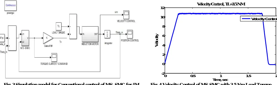
Fig. 3 Simulation model for Conventional control of MS_SMC for IM Fig. 4 Velocity Control of MS-SMC with 3.5 Nm Load Torque
In fig. 3 we can see simulation part of multi segment sliding mode control which is implemented in Induction motor. So, We can give different types of torque by load torque block and get waveform at different load.
In fig. 4 and fig. 5 waveform is taken for 3.5 Nm load torque. For fitness function GA based simulation is added which is in fig. 6.
0 0.5 1 1.5 2
-2 0 2 4 6 8 10 12
Time, sec
V
e
lo
c
it
y
Velocity Control, TL=3.5 N M
Velocity Control
|
|
1
50
1
1u
W
f
S
F
fit i i
FIG.5POSITION CONTROL OF MS-SMC WITH 3.5NM LOAD TORQUE FIG.6FITNESS FUNCTION FOR GA BASED SIMULATION
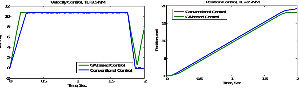
In fig. 6 and fig. 7 waveform comparison are shown. By that we can see GA based control and conventional control of velocity as well as position.
Comparative analysis of Simulation model for GA based Parameter tuning of MS-SMC along with Conventional control strategy for IM.
Fig. 7 Velocity Response Comparisons for TL=3.5 NM Fig. 8 Position Response Comparisons for TL=3.5 NM
After Comparing all the result genetic algorithm based parameter tuning provides reduced chattering in comparisons with the conventional control strategy.
VII. CONCLUSION
Trapezoidal speed command profile of MS-SMC system for an IM servo drive has been presented. It has three parts: (i) constant acceleration, (ii) constant speed and (iii) constant deceleration. The dynamics of the multi-segment sliding mode controlled IM servo drive fully satisfied the desired speed and acceleration of the rotor in the speed control mode of the incremental motion. Also, the proposed MS-SMC system is invariant to perturbations. In addition, a real-time GA has been proposed and implemented for on-line tuning of the control gains in the MS-SMC. As a consequence, chattering in the torque current commands is significantly reduced for the GA-based MS-SMC scheme. It has Good dynamic responses of the rotor position are maintained with regard to external load disturbance. The validity of the
0 0.5 1 1.5 2
0 5 10 15 20
Time, Sec
P
o
si
ti
o
n
,r
a
d
Position Control, TL=3.5 N M
Position Control
0 0.5 1 1.5 2
-2 0 2 4 6 8 10 12
Time, Sec
V
e
lo
c
it
y
Velocity Control, TL=3.5 NM
GA based Control Conventional Control
0 0.5 1 1.5 2
0 5 10 15 20
Time, Sec
P
o
s
it
io
n
,
ra
d
Position Control, TL=3.5 NM
REFERENCES
[1] Gopal, M., “Digital Control and State Variable Methods”, Conventional and Neural-Fuzzy Control Systems, Second Edition, Tata
McGraw-Hill Publication, 2004.
[2] E. E. El-Kholy, “High Performance Induction Motor Drive Based on Adaptive Variable Structure Control”, the 30th Annual Conference of the
IEEE Industrial Electronics Society, November 2 - 6, 2004.
[3] Rong-Jong Wai, Jeng-Dao Lee, and Kuo-Ho Su., “Supervisory Enhanced Genetic Algorithm Control for Indirect Field-Oriented Induction
Motor Drive”, IEEE Transactions paper 0-7803~8359-1/2004.
[4] Christopher Edwards and Sarah k. Spurgeon, “Sliding Mode Control Theory & Application”, Taylor and Francis Publication, 2009.
[5] K. F. Man, Member, IEEE, K. S. Tang, and S. Kwong, “Genetic Algorithms: Concepts and Applications”, IEEE Transactions on Industrial
Electronics, Vol. 43, No. 5, October 1996.
[6] Goldberg, David E., “Genetic Algorithm in Search, Optimization, and Machine Learning”, Pearson Education Publication, 2000.
[7] Melanie Mitchell, “An introduction to Genetic Algorithm”, Prentice Hall Publication, 1996.
[8] Anup Kumar Singh, Nallapaneni Manoj Kumar, Swapnajit Pattnaik, K. Vinay Reddy, “Speed Control of 3-Phase Induction Motor fed
Through Direct Matrix Converter using GSPWM Technique with Unity Input Power Factor”, International Conference on Electrical Power and Energy Systems (ICEPES) Maulana Azad National Institute of Technology, Bhopal, India,IEEE TRASACTION 2016.
[9] Ms. Tripti Rai, Prof. Prashant Debre, “Generalized Modeling Model Of three phase Induction Motor”, IEEE conference 2016.
[10] Muhammad Junaid Asif,Tayyab Shahbaz, Syed Umair Hassan, Syed Tahir Hussain Rizvi, “Mathematical Modelling of 3-phase Induction
motor to study the Torque vs. Speed Characteristics using MATLAB Simulink”, IEEE TRASACTION 2016.
[11] P. Chrin, P. Maussion, Pietrzak-David, B. Dagues, “Modeling of 3-phase Induction Machine as Single Phase Generator for Electricity
Generation from Renewable Energies in Rural Areas”, IEEE conference 2015.
[12] Muhammad Asad, Muhammad Arif, Uzair Khan, “Speed control of Induction Motor via Fuzzy Proportional Integral (FPI) Controller”, IEEE
TRASACTION 2016.
[13] Ahmed A. Zaki Diab, Vladimir V. Pankratov, “SLIDING MODE CONTROL OF VECTOR CONTROLLED INDUCTION MOTOR DRIVE,
“IEEE TRANSACTION 2012.
[14] HUANG Peng,HUANG Lei,MIAO Changyun, “Study on Multi-segment sliding-mode-control-based Servo System”, IEEE 2013.
[15] Junhui Zhao, Caisheng Wang,Feng Lin, Fellow,Le Yi Wang, Zhong Chen, “Novel Integration Sliding Mode Speed Controller for Vector
Controlled Induction Machines”, IEEE TRANSACTION 2011.
[16] Kuo-Kai Shyu, Member,Chiu-Keng Lai, “Incremental Motion Control of SynchronousReluctance Motor Via Multisegment Sliding
ModeControl Method”, IEEE TRANSACTIONS ON CONTROL SYSTEMS TECHNOLOGY, VOL. 10, NO. 2, MARCH 2015.
[17] Kuo-Kai Shyu, Member, IEEE, and Chiu-Keng Lai, “Incremental Motion Control of Synchronous Reluctance Motor Via Multisegment