ISSN(Online): 2320-9801 ISSN (Print): 2320-9798
I
nternational
J
ournal of
I
nnovative
R
esearch in
C
omputer
and
C
ommunication
E
ngineering
(An ISO 3297: 2007 Certified Organization)
Vol. 3, Issue 2, February 2015
Design and Modeling of I2C Bus Controller
Using VHDL
Pankaj Kumar Mehto*, Ashish Radhuvansi , Sonu Lal
M.Tech, Dept. of EC, IES College of Technology, Bhopal, India M.Tech, Dept. of EC, IES College of Technology, Bhopal, India Assistant Professor, Dept. of EC, IES College of Technology, Bhopal, India Corresponding author
ABSTRACT: In this paper we focus on the design of I2C bus controller and the interface between the two integrated
devices i.e. microcontroller and EEPROM, the microcontroller like as a master controller and, the EEPROM like as slave for serial communication in embedded system. The I2C Interface is operating in 7-bit address mode. We can say one master is able to manage 27 or 128 slaves. The components of the I2C bus controller is consist of only a bidirectional two wire and standard protocol which communicate between two integrated circuit or device. First one is serial data (SDA) line and second is serial clock (SCL) line. The I2C protocol was given by Philips Semiconductors for faster devices to communicate with slower devices and each other without data loss. The complete module of I2C bus controller is designed in VHDL and simulated in ModelSIM. The design is also synthesized in Xilinx XST 14.1.
KEYWORDS: I2C Bus, microcontroller, VHDL, ModelSIM, Xilinx XST 14.1.
I. INTRODUCTION
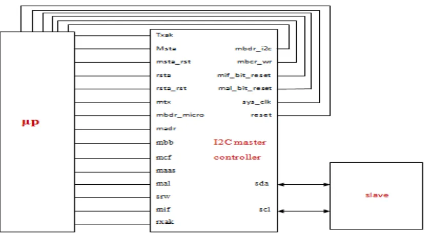
The I2C Master Controller is designed to interface with up to 127 different I2C slave devices. In order to achieve this task, the I2C Master Controller requires several components to make a complete I2C bus interface system. The first components required are a microprocessor and second chip select unit and others I2C slave devices. The microprocessor initiates and configures to all I2C bus transactions. After that, the chip select unit assures that the microprocessor's bus cycles comply to the I2C Master Controller requirements. So, the I2C slave device can be any I2C slave device operating within the specification created by Philips Semiconductor. This thesis is aimed at designing of a Master controller for I2C bus using the VHDL. I2C is a two-wire, bi-directional serial bus thatprovides a simple and efficient method of data exchange between devices. It is most useful for applications requiring occasional communication over a short distance between many devices. The I2C standard is a real multi-master bus including collision detection and arbitration that prevents data corruption if two or more masters attempt to control the bus at the same time. This core, however, supports only single master operations, in which the core is the master. The I2C interface uses a serial data line (SDA) and a serial clock line (SCL) for data transfers.
II. I2CBUSCONTROLLERDESIGN
I2C Protocolgenerally, a standard communication protocol consists of four parts: 1) START signal generation
ISSN(Online): 2320-9801 ISSN (Print): 2320-9798
I
nternational
J
ournal of
I
nnovative
R
esearch in
C
omputer
and
C
ommunication
E
ngineering
(An ISO 3297: 2007 Certified Organization)
Vol. 3, Issue 2, February 2015
III. INTERFACINGSERIALEEPROM(AT24C16)WITH8051MICROCONTROLLER(AT89C51)
USINGI2CBUS
Figure 1 Architecture of AT89C51 microcontroller and AT24C16 EEPROM Interfacing
IV. I2CBUS ARCHITECTURE
ISSN(Online): 2320-9801 ISSN (Print): 2320-9798
I
nternational
J
ournal of
I
nnovative
R
esearch in
C
omputer
and
C
ommunication
E
ngineering
(An ISO 3297: 2007 Certified Organization)
Vol. 3, Issue 2, February 2015
system:
Chip decides on must be synchronized to the microprocessor clock frequency.
Address and data must be applicable the entire time chip select is asserted during a write cycle.
Data is latched into the appropriate I2C Master Controller registers on the rising edge of the third microprocessor clock.
Data strobe acknowledges is controlled externally to the I2C Master Controller. It is up to the designer to insert the appropriate wait states to achieve the requirements above.
VI. TOP-LEVEL SIGNAL DESCRIPTIONS
Table-1 consists of the input/output signals of the I2C bus Master bus controller. The address bus is used to 3-bit input pin for the I2C master bus controller. The data input to the master bus controller is 8-bit and data output from the master bus controller is too 8-bit. Serial data line (SDA) and Serial clock line (SCL) both are in out pins between master controller and slave devices. Chip Select is the input pin to the controller which is synchronizes with the clock from microprocessor. RD and WR both are input pins to the master controller from the microprocessor.
Table1 Signal Description of I2C Master Controller
Signal Type Description
madr [7:0] Input I2C slave address mbdr_i2c [7:0] In-out I2C data for uP
mbdr_micro Input uP data to output on I2C bus sda In-out I2C serial data
Scl In-out I2C serial clock cs Input master/slave select
srw In-out slave read/write from microprocessor txak Input I2C write signal from microprocessor Sys_clock Input I2C Input clock from microprocessor reset Input Reset
msta_rst Out resets MSTA bit if arbitration is lost rsta Input repeated start
rsta_rst Out repeated start reset mbb Out bus busy
mcf In-out data transfer maas In-out addressed as slave mal In-out arbitration lost mif Out interrupt pending
mbcr_wr Input indicates that MCBR register was written mif_bit_reset Input indicates that the MIF bit should be reset mal_bit_reset Input indicates that the MAL bit should be reset
VII.DESIGN STEPS
ISSN(Online): 2320-9801 ISSN (Print): 2320-9798
I
nternational
J
ournal of
I
nnovative
R
esearch in
C
omputer
and
C
ommunication
E
ngineering
(An ISO 3297: 2007 Certified Organization)
Vol. 3, Issue 2, February 2015
VIII. FLOWCHART
Figure 1.3 Communication application flowchart
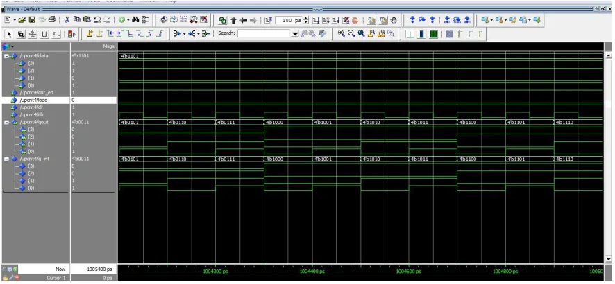
IX. SIMULATION RESULT
The VHDL code for I2C master controller is compiled in the ModelSim PE Student Edition 10.4 software tool. The test bench of this module is simulated and followings are the results.
Here in all the cases I have taken clock frequency of 20MHZ that is time period of 50ns and duty cycle of 50%.
ISSN(Online): 2320-9801 ISSN (Print): 2320-9798
I
nternational
J
ournal of
I
nnovative
R
esearch in
C
omputer
and
C
ommunication
E
ngineering
(An ISO 3297: 2007 Certified Organization)
Vol. 3, Issue 2, February 2015
Figure1.5 Data register of I2C master controller.
ISSN(Online): 2320-9801 ISSN (Print): 2320-9798
I
nternational
J
ournal of
I
nnovative
R
esearch in
C
omputer
and
C
ommunication
E
ngineering
(An ISO 3297: 2007 Certified Organization)
Vol. 3, Issue 2, February 2015
Figure1.7 Header data register of I2C master controller.
X. CONCLUSION
The results of simulation and desired behaviour of the I2C bus controller agree. The interfacing of microcontroller (master) and serial EEPROM (slave) has done by using I2C bus which elaborates that I2C components are working as our desired conditions. The design of I2C controller using VHDL, simplifies the design process. The designer can write his design report not including any specific fabrication equipment. If a new technology emerges, designers do not require redesigning the circuit. He plainly input the intend program to the logic synthesis tool and creates a new gate level netlist using the new fabrication equipment. The judgment synthesis tool will optimize the circuit in area and timing for the new technology.
ACKNOWLEDGEMENT
The correspondence author is thankful to all the faculty members of department of Electronics & Communication, IES College of Technology Bhopal, M.P. and India for continuous support and encouragement. This is an opportunity to prove our technical skill for the benefit of social civilization.
REFERENCES
1. D. Paret: Le bus I2C, de la théorie à la pratique, ISBN2100017179, ed. DUNOD, Paris 1993.
2. IEEE Computer Society. IEEE Standard Verilog® Hardware Description Language, IEEE Std 1364-2001, The Institute of Electrical and Electronics Engineers, Inc,28 September 2001.
3. J. Bhaskar, second Edition, BSP, A Verilog HDL Primer.
4. Muhammed Ali Mazidi, Janice Gillispie Mazidi & Rolin D. Mckinlay, second Edition, Pearson Education. The 8051 Microcontroller and Embedded Systems, using Assembly and C.
5. M. D. Ciletti. Advanced Digital Design with the Verilog HDL, Publishing House of Electronics Industry, 2004.4
6. http://www.engineersgarage.com/microcontroller/8051projects/interface-
7. serial-eeprom-24c02-AT89C51-circuit
http://www.charmedlabs.com/index.php?option=com_smf&Itemid=36&topic=640.0.
8. SAA1064, 4-digit Led-driver with I2C bus interface datasheet, http://www.semicondutors.philips.com