Copyright to IJIRSET www.ijirset.com
136
Identification of the Presence of Train and its
Formation
Pavithradevi. V1, Roopini. D2, Rumana Vaseela Abdul Aleem3, Solai Shree. V4
UG Student, Dept. of ECE, Sri Ramakrishna Institute of Technology, Coimbatore, TamilNadu, India1. UG Student, Dept. of ECE, Sri Ramakrishna Institute of Technology, Coimbatore, TamilNadu, India2. UG Student, Dept. of ECE, Sri Ramakrishna Institute of Technology, Coimbatore, TamilNadu, India3. UG Student, Dept. of ECE, Sri Ramakrishna Institute of Technology, Coimbatore, TamilNadu, India4.
ABSTRACT: This paper presents an alternative for the Track Circuit and the Axle Counter which are used currently by the Indian Railways to find the presence and details of the train. Load Cell replaces the track circuit and the RFID technology is used to detect the train’s number from which the details of train are retrieved. Using this, the number of wagons in a train can also be detected. The various studies and experiments showed that this method uses less power in comparison with the conventional st yle.
KEY TERMS- Track Circuit, Axle Counter, Load Cell, RFID
I. INTRODUCTION
The vastness of railways – cars, cargo, track, countries and conditions presents a massive challenge for management of rolling stock and rail operations. IPICO’s low cost, passive RF technolog y enables consistently accurate identification and control of assets in virtually any operating environment. As a freight giant, the railway industry is looking forward to improve the utilization of the wagons and has been on a look out for an online system for tracking wagons on its 62000 km worth of rail network. It is expected to identify the possible problem areas and come out with strategies to eliminate them. Under the Information Technology Vision 2012, announced in the Railway Budget for 2008-09 and 2009-10, the railway ministry plans to give the Railways a modern look and feel by implementing Modern Communication systems such as RFID, GPS and GIS. Modernisation of Indian Railways has always been a question in focus for the development of the basic infrastructure of India. Since the railways represent one of the best modes of transport available to the common people, it would be impossible to just keeping increasing the fares to meet the costs incurred due to maintenance, the large workforce and the expansion activities. The Railways should therefore, consider upgrading itself to cutting-edge technologies for better efficiency and cost reduction.
II.EXISTING SYSTEM
Copyright to IJIRSET www.ijirset.com
137
to each rail and a relay coil wired across them. When no train is present, the relay is energised b y the current flowing from the power source through the rails. When a train is present, its axles short (shunt) the rails together; the current to the track relay coil drops, and it is de-energized. Circuits through the relay contacts therefore report whether or not the track is occupied.
Each circuit detects a defined section of track, such as a block. These sections are separated b y insulated joints, usually in both rails. To prevent one circuit from falsely powering another in the event of insulation failure, the electrical polarity is usually reversed from section to section. Circuits are commonly battery-powered at low voltages (1.5 to 12 V DC) to protect against line power failures. The relays and the power supply are attached to opposite ends of the section to prevent broken rails from electricall y isolating part of the track from the circuit. A series resistor limits the current when the track circuit is short-circuited, saving battery power.
Track circuits, though seem to be an eminent one, may suffer from the following limitations.
A broken rail or wire will break the circuit between the power supply and the relay, de-energizing the relay.
A failure in the power supply will de-energize the relay.
A short across the rails or between adjacent track sections will de-energize the relay.
Longer trains with more wheels have better conductivity. Short trains or single engines can be a problem. Trains with a single Budd rail motor, which are also lightweight, and with disc brakes, had some problems when they stopped, and had to make a double stop to ensure good contact with the rails.
Mechanical failure of the relay, causing the relay to be stuck in the "track clear" position even when the track is occupied.
Conditions which partially or completely insulates the wheels from the rail, such as rust, sand, or dry leaves on the rails. This is also known as "poor shunting".
Conditions in the track bed (roadbed) which create stray electrical signals, such as muddy ballast (which can generate a "battery effect") or parasitic electrical currents from nearby power transmission lines.
Parasitic oscillations in the equipment that controls the track circuits.
A more persistent problem is rust. Usually the railhead is kept clean of rust by the regular passage of trains' wheels. Lines which are not used regularly can become so rusty as to prevent vehicles being detected.
Copyright to IJIRSET www.ijirset.com
138
Taking into considerations the above failures, Load Cell seem to be more efficient. “Axle counters” refers to subsystems which are utilized for track vacancy detection on fixed-guide way transport systems such as railways. Axle counters function b y detecting the presence and travelling direction of wheels at various points along the right of way. The right of way is broken into “blocks” with wheels (axles) being counted into and out of the block. If the same amount of axles is detected departing the block as were previously detected entering it, the block is considered vacant.
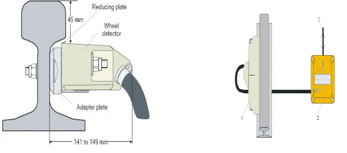
Axle counters primarily consist of two types of components: axle counting head and axle counting computer (sometimes referred to as an evaluation computer). The axle counting heads are mounted alongside the rail profile and actuall y detect the presence of wheels. They typically use LC oscillators to detect when the flange of a railroad wheel has modified the magnetic field created around the axle counter. The evaluation computer typicall y resides in a signal control enclosure alongside the wayside. The evaluation computer generates data based on the axle counting heads and generates either a vacant or occupied declaration of one or more blocks (track sections).
Fig. 3 Axle Counter field equipment Layout.
Copyright to IJIRSET www.ijirset.com
139 II.PROPOSED SYSTEM
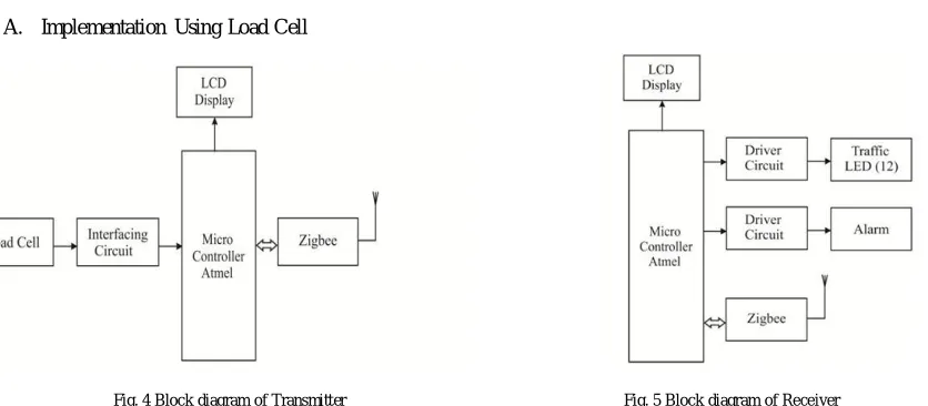
A. Implementation Using Load Cell
Fig. 4 Block diagram of Transmitter Fig. 5 Block diagram of Receiver
Copyright to IJIRSET www.ijirset.com
140
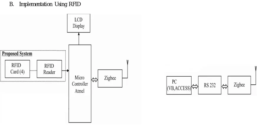
B. Implementation Using RFID
Fig. 6 Block diagram of Transmitter section Fig. 7 Block diagram of Receiver section
Radio-frequency identification (RFID) is the wireless non-contact use of radio frequency electromagnetic fields to transfer data, for the purposes of automatically identifying and tracking tags attached to objects. It is a means of identifying an item based on radio frequency transmission. This technolog y can be used to identify, track and detect a wide variety of objects with the help of two components: Tag and Reader. Communication takes place between a reader and a transponder (derived from TRANSmitter / resPONDER- Silicon Chip connected to an antenna), usually called “tag”.With Load Cell the presence of train is known and b y using RFID, the details of a particular train such as the train number and the number of wagons can be continuously monitored. The RFID reader is placed on the Track and the RFID tags are placed on each wagon in a train. When the train passes on the track, the reader receives signal from the tag i.e. the tag responds to the queries of reader. When the reader receives the signal it sends to PC via Zigbee or GSM. For the prototype, 4 RFID cards are used. Applying RFID to identification of details of train, Collision between trains can be avoided. The PC receives signal from RFID. For management of database about the details of the train, Visual Basic can be used. Using VB we can display the details of the train and this can be used in stations for the reference of passengers also.
IV.RESULTS
A.Implementation Using Load
Cell
When there is no train on track (i.e) track is free near the ULC then at the receiver side (at ULC) the LCD displays
Copyright to IJIRSET www.ijirset.com
141
and additionally a buzzer can be blown to warn the trespassers that a train is approaching the ULC.
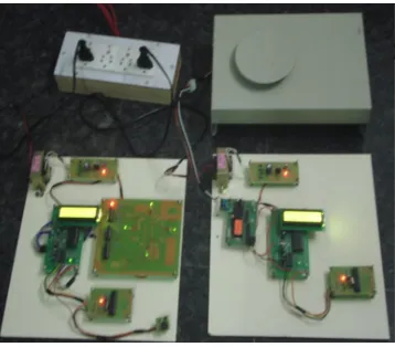
Fig. 8 Model of no train on track Fig. 9 Model of train on tr ack
B.Implementation Using RFID
When no train passes over the track on which the tag is placed, the VB in PC displays “NO TRAIN ON TRACK”. And when the train passes, it displays train number depending on which train passes.
Copyright to IJIRSET www.ijirset.com
142 V.CONCLUSION
REFERENCES
[1] Adriana M.Adami; Misha Pavel;Tamara L.Hayes “Detection of move ment in bed using unobtrusive load cell Sensors”,IEEE transaction on Information Technology in Biomedicine,Vol.14,No.2,March 2010.
[2] R.Ramachandran; J.Thomas Joseph Prakash “FPGA based SOC for Railway Level Crossing Management System”, International journal of Soft Computing and Engineering,Volume 2,Issue-3,July 2012.
[3] Amitabh , P. C. Sharma (2004) “Safety as Ke y Business Theme! -Indian Railways Perspective”, International Railway Safety Conference. [4] Sandhya gautam, Sandip nemade, Teena sakl a (2010) “Simulation of an anti-collision system on same track for Railways”, International Journal of E ngineeri ng and Technology Vol. 2(9), 2010, 4832-4837
[5] Debashreet Das “RFID Deployme nt in Indian Railways: A case study of E-Transport Initiative in India”, International Journal of Instrumentation, Control & Automation (IJICA), V olume 1, Issue 1, Pg:55-60,2011.
[6] Alírio J. Soares Boaventura; Nuno Borges Carvalho “A Battery less RFID Remote Control System”, IEEE Transactions on microwave t heory and techniques, vol . 61, no. 7, Jul y 2013.
[7] Jiwhan Li m; Sangjin Ki m; Heekuck Oh; Donghyun Kim “A Desi gnated Query Protocol for Server less Mobile RFID Systems with Reader and Tag Privacy”, Tsinghua Science And Technology, Volume 17, Number 5, Pg:521-536, Volume 17, Number 5, October