Thermal Design of Heat Sink and
Optimization of Fin Parameters
Srikanth. V
1, Ramesh.C.G
2Department of Mechanical Engineering, Sir MVIT, Bangalore, India.1
Department of Mechanical Engineering, Sir MVIT, Bangalore, India.2
ABSTRACT: Radar is an electronic system that is widely used in the field of object detection to determine the range, velocity and angle of objects. Radar systems consist of various components that produce excessive heat during operation. Since usually these components are housed on a thermally conducting material, thermal design and analysis of such systems plays a very important role in ensuring optimal functionality of radar. Air cooled radar transmitter system is considered here. The aim of this paper is to ensure the optimum functioning of a transmitter unit by maintaining the maximum temperature at a specified location on the thermal base plate to within 70℃. The environment temperature is considered to be 49℃ which determines the range of temperature in which the radar system is used. This involves the design of a heat sink that is effective in dissipating the heat that is rejected onto it by the components at this specified location. It is known that around 420Watts of heat is being rejected onto an area of around 71.25cm2 on the heat sink. The material of the heat sink used is Copper. Commercially available software packages like PTC Creo Parametric 3.0 and Autodesk CFD simulation 2012 are used for modelling and analysis respectively. Analysis is carried out with the operating conditions of air cooled transmitter system given as input. Theoretical validation of the CFD result is carried out and excellent convergence in obtained. MATLAB is used in plotting the various graphs which determine the final fin parameters of the newly designed copper heat sink. Comparisons of the design currently in use in a manufacturing company for the aforementioned scenario versus the new design is presented.
KEYWORDS: Triangular fin, Rectangular fin, Efficiency, Effectiveness, fin spacing, Optimum thickness.
I.INTRODUCTION
has provided the expressions for fin parameters of triangular fins which are used to evaluate the performance of the existing design of the heat sink.
This paper includes the evaluation of the existing design of the heat sink having trapezoidal fin array with thickness of 2.75mm at the base to 1.5mm at the tip. Various parameters like heat flow though the fin, efficiency, effectiveness and number of fins required to dissipate the heat are calculated. Due to space constraints currently only 25 fins are being employed. A new design of the heat sink having rectangular fin array is proposed. Fin parameters of the two designs are compared and tabulated.
II.METHODS AND PROCEDURE
A. Existing design evaluation
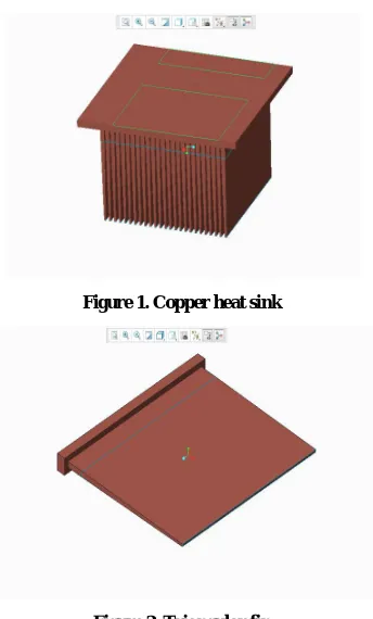
Figure 1. Copper heat sink
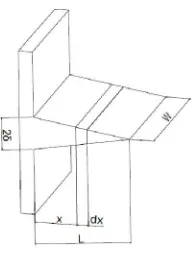
Figure 2. Triangular fin
The above figures show the triangular fin array currently in use. It consists of 25 fins. The heat rejected on the heat sink is known to be 420 Watts on the split line area on the top surface as shown.
i. Fin Calculations
The expression for rate of heat transferred through the fin is given by
= 2 √ℎ (2 √ )
Where,
and are Modified Bessel functions of first and second kind of first order.
ℎ is the convective heat transfer coefficient.
is thermal conductivity of fin material. i.e. Copper.
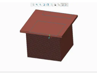
Figure 3. Triangular Fin Dimension
= −
2
= ℎ
The Number of fins required is calculated using the expression
=
The efficiency of the triangular fin,
=
2 √ℎ (2 √ )
(2 √ )
2 ℎ
The effectiveness of the fin is given by,
ε =
2Wθ √hkδ I 2B√L
Where
is the base cross sectional area
= ( − )
The results obtained for the above relations for the existing dimensions of the fin
Given = 112 ; = 0.90 ; = 1 ; = 300 ⁄ ;
ℎ= 37.380 ⁄ ; = 49
For = 80
1. = 15.06
2. ≅28
3. = 73.12%
4. = 35.0968
For = 70
1. = 10.2014
2. ≅42
3. = 73.12%
4. = 35.0968
The existing design consists of 25 fins with 1mm fin spacing which is not sufficient for effective cooling with the current set up of forced air convection at 100CFM.
B. New design of heat sink
Figure 5. Rectangular fin
Figure 6. Forced Convection of fin array [3]
The following derived relations were obtained from the book Thermal Design by HoSung Lee [3]
1. = 2.725
2. ℎ = 0.664 / /
3. = 1.419
4. ( ) =
/
ℎ
5. =
i. Existing conditions of operation
Width of Cutout for heat sink on Thermal base plate W=118mm
Length of flow L = 112mm
Reynolds Number = 5.04 × 10 (Laminar Region)
Properties of Air at 49
1. = 1.093 /
2. = 19.61 × 10 /
3. = 17.95 × 10 /
4. = 25.722 × 10 /
5. = 0.698
6. = 1005 /
7. = 0.02826 /
Therefore substituting in the above derived relations
1. = 1.2 2.ℎ = 37.380 ⁄
ii. MATLAB plots of the derived relations and optimization with heat flux constraint
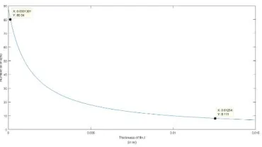
For the existing total heat flux constraint of 420W being ejected onto the heat sink, keeping the flow length = 112 constant, the resulting optimized values of fin dimensions are derived using the above plots obtained using MATLAB.
Figure 7. Q(total) vs Optimum thickness of fin
Figure 9. Height of fin vs Optimum Thickness
For = 420 ,
= 12.54≅13 ; = 8.11≅9; = 318.3
NOTE: The plot consists of 2 data points between which heat transferred by the fin array is more than the required level of 420Watts. The obtained height of the fin ( ) is very large. The height constraint in the design is at a maximum value of 90mm. Thus the above design is to be modified by taking into consideration the height constraint.
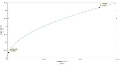
iii. Optimization of fins with constraints using MATLAB plots
Now we want to obtain an optimum heat sink with the constraints which are the profile length = 90 and keeping = 112 constant as before. We seek an optimum thickness t as a function with the given profile length b as shown in the plot.
Figure 12. Q(total) vs Optimum thickness of fin
For = 90 , we get Optimum thickness of fin,
= 1 Number of fins required,
= 49.12≅50 Total heat flux transferred by the obtained fin array,
( ) = 722.2
Efficiency of the fin,
= tanh ( )
= 62.70% Effectiveness of fin,
=
ℎ tanh ( )
= 113.227
III.RESULTS AND CONCLUSION
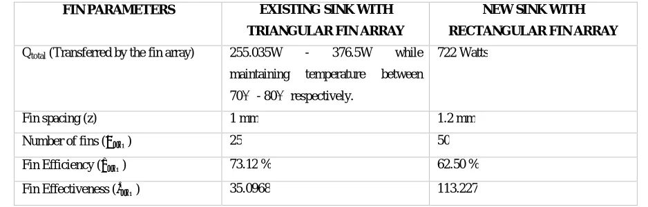
The below table gives a comparison of the performance of the two heat sink designs discussed above.
FIN PARAMETERS EXISTING SINK WITH
TRIANGULAR FIN ARRAY
NEW SINK WITH
RECTANGULAR FIN ARRAY
Qtotal (Transferred by the fin array) 255.035W - 376.5W while
maintaining temperature between
70℃ - 80℃ respectively.
722 Watts
Fin spacing (z) 1 mm 1.2 mm
Number of fins ( ) 25 50
Fin Efficiency ( ) 73.12% 62.50 %
1. It is seen that the rectangular heat sink design dissipates 722 Watts as opposed to the required level of 420 watts in the current configuration.
2. The new heat sink design with rectangular fin array has a spacing of 1.2mm which is the optimum value as calculated and the existing design has a fin spacing of 1mm which is not sufficient for effective cooling. 3. It is seen that the efficiency of rectangular fin is around 10 % less than that of the Triangular fin.
4. It is also observed that the effectiveness of the rectangular fin is more than three times that of the triangular fin.
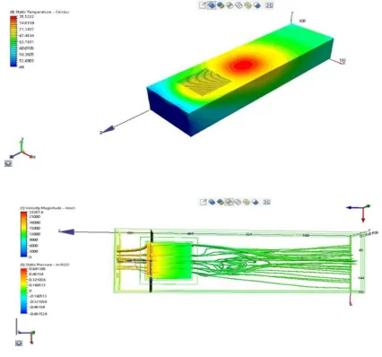
IV.THEORETICAL VALIDATION OF NEW DESIGN OF HEAT SINK
The following fin parameters were arrived at during the design of the new copper sink.
1. = 1.2 ; 2.ℎ = 37.380 ⁄ ; 3. = 112 ; 4. = 90 ; 5. = 1 ;6. = 49.12≅50 ;
7. ( ) = 722.2 ; 8. = 62.70% ; 9. = 113.227
We know that the expression for heat transferred by a rectangular fin for the case of end fin being insulated is given by [5]
,
= ℎ tanh
Where =
Therefore substituting the obtained fin parameters in the above equation for dissipation of a total heat flux of 420 Watts, we get the expected base temperature value (the only unknown in the above equation)
= 66.57℃
When compared to the above obtained result of around 68℃ on the heat sink with the new design, the percentage of error that exists between the analytical result and the experimental result is found to be at around 2%. Hence this proves an excellent convergence of the CFD results.
REFERENCES
[1] Sandhya Mirapalli, Kishore.P.S (2015). “Heat Transfer Analysis on a Triangular Fin”. International Journal of Engineering Trends and Technology (IJETT).Volume 19 Number 5.
[2] R.Mohan and Dr.P.Govindarajan (2010). “Thermal Analysis of CPU with variable Heat Sink Base Plate Thickness using CFD”.
International Journal of the Computer, the Internet and Management. Volume 18 Number 1.
[3] Hosung Lee (2010). Thermal Design: Heat Sinks, Thermoelectrics, Heat Pipes, Compact Heat Exchangers, and Solar Cells.
ISBN 978-0-470-49662-6, John Wiley & Sons, Inc.
[4] M. Tirumaleshwar (2009). “Fundamentals of Heat and Mass Transfer” . ISBN 9788177585193. Pearson Publication. [5] R.K.Rajput (2015). “Heat and Mass Transfer” . ISBN 9789385401930. S.Chand Publication.
![Figure 6. Forced Convection of fin array [3]](https://thumb-us.123doks.com/thumbv2/123dok_us/1504873.1184231/5.595.201.390.181.506/figure-forced-convection-of-fin-array.webp)