Cogging Reduction in Permanent Magnet Machines via Skewed Slot
Opening and Its Analytical Modeling
Md M. Reza* and Rakesh K. Srivastava
Abstract—Air-gap magnetic energy variation with angular position produces cogging torque, which
may results in mechanical vibration, acoustic noise, and torque ripple. Various cogging reduction methods of design modifications viz. skewed magnets, skewed slot, asymmetrical displacement of magnets/slots, etc. are reported in the literature. All such methods adversely affect machine performance in terms of air-gap magnetic field, back emf, and induced voltage. This paper introduces the cogging torque reduction by skewing of slot opening. In order to obtain machine performance, the no load magnetic field of the proposed machine is determined using combined methods of two-dimensional subdomain analytical analysis method and multislice method. The machine is considered as a stack of slices along axial direction. The adjacent slices differ in relative location of slot openings. The analytical field solution of each slice is obtained by use of subdomain method, and algebraic summation of slices is taken as field solution of actual machine. The analytical analysis developed is compared with finite element analysis (FEA). The close agreement of analytical results with FEA results confirms the validation of analytical solution. Furthermore, the machine parameters viz. cogging torque, back emf, and induced voltage are evaluated analytically, and results are compared with FEA solution. To demonstrate the effect of skewed slot opening on machine’s performance, a machine of same rating without skewing of slot opening is investigated, and their performances are compared.
1. INTRODUCTION
The advent of permanent magnets with high energy density and linear demagnetization characteristic has attracted the electrical machine manufacturing industry towards development and design of permanent magnet (PM) machines. Additional advantages such as high power density, efficiency, power factor, torque capacity, and ease of PM machines control make them advantageous over other alternatives. Nowadays the PM machine drive application widely covers small as well as medium power applications ranging from domestic appliances for example, brushless dc (BLDC) motor for fan, blower, dryer, grinders applications, and many more to medium power utilizations such as electrical vehicle drives, wind power, and tidal wave energy generator. However, the cogging torque produced in PM machine is due to airgap magnetic energy variation with machine peripheral distance. Cogging torque is always a well-known problem of permanent magnet machine, which may cause mechanical vibration, acoustic noise, and torque ripple. Cogging torque significantly affects the machine performance and is severe in case of light load, low speed, and direct drive applications.
The interaction of permanent magnet flux and the permeance variation arises because of slots and tooth result in airgap magnetic energy variation with relative angular position of magnets and stator. This angular variation of airgap magnetic energy results in magnetic torque commonly known as cogging torque and is present even in absence of armature excitation. Cogging torque may cause mechanical vibration, acoustic noise, and torque ripple. These effects are significant and severe for
Received 19 April 2018, Accepted 29 June 2018, Scheduled 19 July 2018 * Corresponding author: Md Motiur Reza ([email protected]).
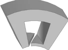
the magnetic flux linkage, electromotive back emf, induced emf, and average torque of the machine. This paper introduces a new method of cogging torque reduction in radial flux permanent magnet machines. The advantage of this method is that it does not compromise the machine’s performance. The cogging torque reduction is achieved by skewing of slot opening. The slot opening is skewed over the slot width. The skewed slot opening is as shown in Fig. 2. Due to skewed slot opening, the airgap magnetic field is distorted, which results in machine performance deviations from unskewed one. However, the magnetic position of armature coil is kept undisturbed. Hence, the machines’s performance deviates very insignificantly from unskewed machine. In order to obtain machine performance, the no-load magnetic field of the proposed machine is determined by combined methods of two-dimensional subdomain analytical analysis and multislice method along axial direction. The field solution is obtained by the use of superposition of solution of magnetic field for each slice. The developed analytical results are compared with finite element analysis (FEA). The close agreement of analytical results with FEA results confirms the validation of analytical solution. Furthermore, the machine parameters viz. cogging torque, back emf, and induced voltage are evaluated analytically, and results are compared with FEA solution. To demonstrate the effect of skewed slot opening on machine’s performance, a machine of same rating without skewing of slot opening is investigated, and their performances are compared.
2. ANALYTICAL MODELING OF PERMANENT MAGNET MACHINE WITH SKEWED SLOT OPENING
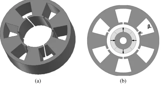
The permanent magnet machine with skewed slot openings is shown in Fig. 1. The stator core of PM machines with skewed slot openings is considered as an axial stack of stator laminated core with gradual variation of slot openings along the axial direction. The slot opening at one end of the machine is at beginning of the slot, while for the other end of the machine the opening is at the other end of the same slot. The possible angular variation of slot opening is αsk=βo−αo, where αo and βo are angular slot
opening and slot width.
(a) (b)
Figure 1. Permanent magnet machine with skewed slot openings, (a) stator with skewed opening, (b)
Figure 2. Single slot diagram of PM machine with skewed slot opening.
2.1. No Load Magnetic Field Distributions in Permanent Magnet Machine with Skewed Slot Opening
The analytical model is developed by combined use of multi-slices method and two-dimensional subdomain analysis. Following assumptions are made to establish the analytical solution
(i) Machine axial length is assumed to be infinite, and hence end effects are ignored. (ii) The permeability of stator and rotor back iron is infinite.
(iii) The demagnetization characteristics of magnet are linear. (iv) Magnetic coupling between adjacent slices is ignored.
The slot opening of each slice is at a different location. Taking center slice as a reference, the actual machine is modeled by considering infinitesimally small thick slicedz located atz. The angular shift of the slot opening of this slice caused by skewing of slot opening isαoi = (z/L)αsk, whereLis axial length
of machine. The angles αi and βi are central angular positions of slot opening and slot corresponding
to theith slot, which is shown in Fig. 3 with respect to the reference coordinate, and are given as
αi = 2i
Qπ+αoi
βi = 2i
Qπ
(1)
whereQis the number of slots. The model shown in Fig. 3 is divided into four types of regions: region 1i (ith slot region), region 2i (ith slot opening region), region 3 (air-gap region), and region 4 (permanent magnet region). The governing equations in coordinate frame attached with stator and centered with machine, the magnetic fieldBin terms of magnetic vector potentialA, under consideration of Coulomb’s
(a) (b)
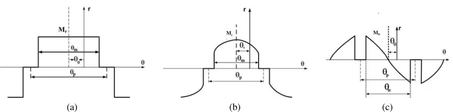
Figure 4. Magnetization distribution of (a) radial component of radial magnetized magnet, (b) radial component, and (c) tangential components of parallel magnetized magnet.
gauge∇ ·A= 0 are given as
∂2A1iz
∂r2 +
∂A1iz
r∂θ +
∂2A1iz
r2∂2θ = 0 (2)
∂2A2iz
∂r2 +
∂A2iz
r∂θ +
∂2A2iz
r2∂2θ = 0 (3)
∂2A3z
∂r2 +
∂A3z
r∂θ +
∂2A3z
r2∂2θ = 0 (4)
∂2A4z
∂r2 +
∂A4z
r∂θ +
∂2A4z
r2∂2θ = −
μo r
Mθ− ∂Mr
∂θ
(5)
where μo is the air permeability. Mθ and Mr are the radial and tangential components of the residual
magnetization vector, respectively. The residual magnetization of radial and parallel magnetized magnets in stator coordinate frame are shown in Fig. 4, which are expressed in Fourier series expansion as [11]
Mr=
∞
n=1,3,5,...
Mrncos(n(θ+θ0))
Mθ=
∞
n=1,3,5,...
Mθnsin(n(θ−θ0))
(6)
wherepis the number of pole-pairs,θ0=ωrt−θi,ωrthe rotor angular speed,θi the initial rotor position
with respect to the reference slot, θm the magnet pitch, θp the pole pitch of machine, and αp =θm/θp.
TheMrn andMθn for radial and parallel magnetized magnet are given in Eqs. (7) and (8) respectively.
Mrn= (4Brp/μ0nπ) sin(nπαp/2p); Mθn = 0; ∀ np = 1,3,5, . . . (7)
and,
Mrn=Brαp(C1n+C2n)/μ0; Mθn =Bθαp(C1n−C2n)/μ0; ∀ np = 1,3,5... (8)
whereC1n and C2n are given in Eq. (9).
C1n=
sin
(np+ 1)αp π
2p
(np+ 1)αp π
2p
; C2n= ⎧ ⎪ ⎪ ⎪ ⎪ ⎨ ⎪ ⎪ ⎪ ⎪ ⎩
1 for np = 1
sin
(np+ 1)αp π
2p
(np+ 1)αp π
2p
for np= 1 (9)
where Br is the residual flux density of the magnet. The boundary conditions derived from Maxwell’s
of infinite permeability allows flux to fall normally at stator and rotor iron core. Mathematically, these boundary conditions are summarized as
B1iθ(r, θ)|r=Rb= 0;B1ir=B2ir|r=Rs;B2ir=B3r|r=Rso;H1θ=H2θ|r=RmB1r=B2r|r=Rm;B1θ(θ, z)|r=Rr= 0
B1ir(θ, z) = 0; ∀θ∈
−βo
2 +βi,
βo
2 +βi
B2ir(θ, z) = 0; ∀θ∈
−αi
2 +βi,
αi
2 +βi
H2iθ|r=Rs = ⎧ ⎨ ⎩
H1iθ; ∀θ∈
−αi
2 +βi,
αi
2 +βi
0; ∀θ /∈−αi
2 +βi,
αi
2 +βi
H3θ|r=Rso = ⎧ ⎨ ⎩
H2iθ; ∀θ∈
−αi
2 +βi,
αi
2 +βi
0; ∀θ /∈−αi
2 +βi,
αi
2 +βi
(10) Apply variable separable method for solving boundary valued problem. The general solutions to the governing equations, the vector potential in all regions are expressed as [11, 12]
A1iz =
∞
k=1
a1in Rs Rb Ek r Rb Ek + r Rs
−Ek
×cosEk
θ+βo
2
(11)
A2iz =
∞
m=1
a2in
r Rs
Fm +b2in
r Rso
−Fm
×cosFm
θ+βo 2 −αso
(12)
A3z =
∞
n=1
a3n
r Rso
n
+b3n
r
Rm
−n
cos (nθ)+ ∞
n=1
c3n
r Rso
n
+d3n
r
Rm
−n
sin (nθ) (13)
A4z = A4p+
∞
n=1
a4n
r
Rm
n
+b4n
r Rr
−n
cos (nθ) + ∞
n=1
c4n
r
Rm
n
+d4n
r Rr
−n
sin (nθ) (14)
whereA4p is the particular solution of Eq. (5), andEk=kπ/βo andFm=mπ/αo are harmonics orders
of magnetic field distributions in slot openings and slots regions. All coefficients involve in solutions:
a1n, b1n, c1n, d1n, a2n, b2n, c2n, d2n, a3in, b3in, and a4in are evaluated with boundary conditions at
interface between subdomain and well explained in papers [11, 12].
2.2. Cogging Torque, Flux Linkage, and Induced Voltage Calculation
obtained no-load magnetic field radial and tangential flux density in the air gap by the use of subdomain method is used for the cogging torque, flux linkage, and induced voltage. The cogging torque is calculated by the use of Maxwell stress tensor, and for infinitesimally small length (dz) machine, the cogging torque is expressed as
dtcog = r
2dz
μo
2π
0
B3rB3θdθ (15)
whereB3rand B3r are radial and tangential flux density components at PM surface. The total cogging
developed in machine is calculated as integration of cogging torque produced due to elementary machine portion over its length.
Tcog =
La/2
−La/2 2π
0
r2
μoB2rB2θdθdz (16)
The flux linkage φi per phase is calculated as
φi =
La/2
−La/2
i
NcRs
a B2rdθdz (17)
where i=A, B, C represents the phases of the stator winding, Nc the number of turns per phase, and athe parallel-circuits per phase. The induced voltage per phase in the winding is evaluated by
Ei =−dφi
dt (18)
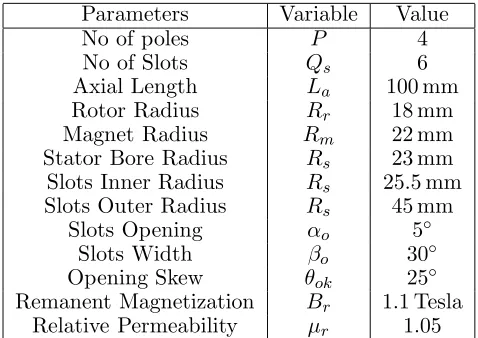
Table 1. Parameters of machines
Parameters Variable Value
No of poles P 4
No of Slots Qs 6
Axial Length La 100 mm
Rotor Radius Rr 18 mm
Magnet Radius Rm 22 mm
Stator Bore Radius Rs 23 mm
Slots Inner Radius Rs 25.5 mm
Slots Outer Radius Rs 45 mm
Slots Opening αo 5◦
Slots Width βo 30◦
Opening Skew θok 25◦
3. COMPARISON OF ANALYTICAL WITH FEA ANALYSIS
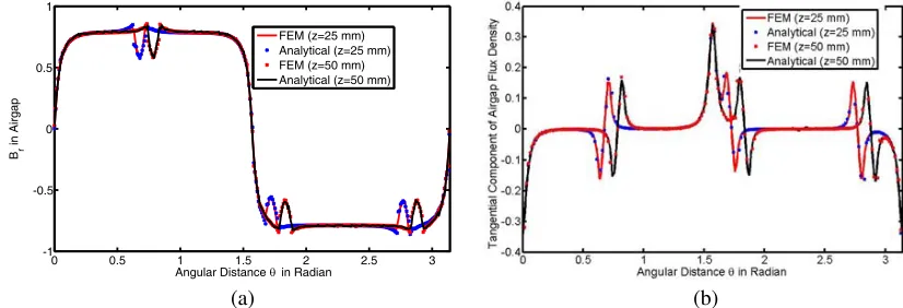
For the validation of the analytical model, a 3D FEM model of PM machine is simulated in Ansoft Maxwell. The machine dimensions given in Table 1 is used. The machine’s slot opening is skewed with an angle 25◦. The slot opening angular position varies with axial length of machine, and hence their effects on the magnetic field are different. To evaluate the effects of slot opening displacement, the radial and tangential components of magnetic field density at different axial length: 1/4th and 1/2th, are obtained from analytical solution and compared with FEA results. These comparisons are
0 0.5 1 1.5 2 2.5 3
1 -0.8 -0.6 -0.4 -0.2 0 0.2 0.4 0.6 0.8 1
Angular Distance θ in Radian
Radial Component of Airgap Flux Density
FEM
Analytical
(a) (b)
Figure 5. Comparison ofBr, and Btat r = (Rm+Rs)/2, andZ = 25 mm.
0 0.5 1 1.5 2 2.5 3
-1 -0.8 -0.6 -0.4 -0.2 0 0.2 0.4 0.6 0.8 1
Angular Distance θin Radian
Radial Component of Airgap Flux Density
FEM Analytcial
(a) (b)
Figure 6. Comparison ofBr, and Btat r = (Rm+Rs)/2, andZ = 50 mm.
0 0.5 1 1.5 2 2.5 3
-1 -0.5 0 0.5 1
Angular Distance θ in Radian
Br
in Airgap
FEM (z=25 mm) Analytical (z=25 mm) FEM (z=50 mm) Analytical (z=50 mm)
(a) (b)
Angluar Position in Mechanical Degree
(a)
Time (ms)
(b)
0 5 10 15 20
-100 -80 -60 -40 -20 0 20 40 60 80 100
Time (ms)
Induced Voltage(v)
FEA Analytical
(c)
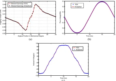
Figure 8. (a) Cogging torque, (b) Flux linkage of phase A, and (c) Induced voltage of phase A.
shown in Figs. 5(a), 5(b), 6(a), and 6(b). The resemblance of analytical and FEM results verify the correctness of analytical solution. Furthermore, the effect of skewed slot opening is realized by plotting the magnetic field densities at different axial lengths as shown in Figs. 7(a) and 7(b). The relative position of slot opening with respect to permanent magnet changes in machine along axial length, and its effects on radial flux density and tangential flux density are reflected in Figs. 7(a) and 7(b). This contributes to a phase displacement in cogging torque waveform produced by each slice and results in reduction of total cogging torque developed in machine. The same physics is responsible for cogging torque reduction in skewed slots permanent magnet machine. However, in skewed slots machine, the magnetic position of armature coil along axial length changes and hence, results in reduction in the flux linkage and induced voltage reduction. In order to elaborate advantages of the proposed method of cogging reduction, the performance of this machine and a machine with unskewed opening is obtained with the help of Ansoft Maxwell simulation. The parameters of unskewed slot opening machine are kept the same as the proposed machine’s parameters (Table 1) with the slot opening skewing angle θok
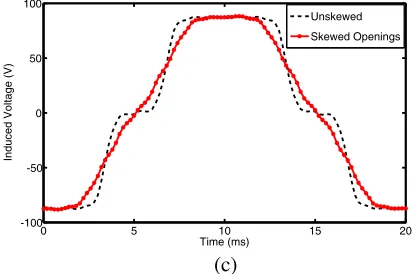
being zero. The performances of the proposed machine are evaluated and compared in Fig. 8. Further comparisons of performances of the proposed machine and the machine with unskewed slots are shown in Fig. 9.
(a)
0 5 10 15 20
-0.2 -0.1 0 0.1 0.2 0.3
Time (ms)
Flux Linkeage (Wb)
unskewed Skewed Openings
0 5 10 15 20 -100
-50 0 50 100
Time (ms)
Induced Voltage (V)
Unskewed Skewed Openings
(c)
Figure 9. Comparison of (a) cogging torque, (b) flux linkage of phase A, and (c) induced voltage of
phase A.
4. CONCLUSION
A new method of cogging torque is proposed. To analyze the effect of this method on machine performance, an analytical model is developed. The analytical result is validated with FEM result, and further investigation suggests that 83% of cogging reduction in permanent magnet machine can be achieved by skewing of slot openings. Furthermore, the flux linkage and induced voltage reduction are insignificant for skewed openings machine. This method of cogging reduction is more advantageous than reported methods as the direct axes of rotor and stator are parallel to each other throughout machine’s axial length for this machine. Hence, this design modification does not increase the complexity of machine control as it happens with other methods: skewed slots, skewed magnets, and asymmetrical displacement of slots/magnets for cogging reduction.
5. RECOMMENDATION
This machine can be used for light load and direct drive applications. For example, it is more suitable for servo application such as positioning motor. It is also useful in aerospace applications where the torque ripple is major concern.
REFERENCES
1. Wanjiku, J., M. Khan, P. S. Barendse, and P. Pillay, “Influence of slot openings and tooth profile on cogging torque in axial-flux pm machines,” IEEE Transactions on Industrial Electronics, Vol. 62, No. 12, 7578–7589, 2015.
2. Zhu, Z. and D. Howe, “Analytical prediction of the cogging torque in radial-field permanent magnet brushless motors,” IEEE Transactions on Magnetics, Vol. 28, No. 2, 1371–1374, 1992.
3. Xia, C., Z. Zhang, and Q. Geng, “Analytical modeling and analysis of surface mounted permanent magnet machines with skewed slots,”IEEE Transactions on Magnetics, Vol. 51, No. 5, 1–8, 2015. 4. Zhu, Z. and D. Howe, “Influence of design parameters on cogging torque in permanent magnet
machines,”IEEE Transactions on Energy Conversion, Vol. 15, No. 4, 407–412, 2000.
5. Hwang, S.-M., J.-B. Eom, G.-B. Hwang, W.-B. Jeong, and Y.-H. Jung, “Cogging torque and acoustic noise reduction in permanent magnet motors by teeth pairing,” IEEE Transactions on
Magnetics, Vol. 36, No. 5, 3144–3146, 2000.
6. Hwang, S.-M., J.-B. Eom, Y.-H. Jung, D.-W. Lee, and B.-S. Kang, “Various design techniques to reduce cogging torque by controlling energy variation in permanent magnet motors,” IEEE
IEEE Transactions on Magnetics, Vol. 34, No. 2, 468–470, 1998.
11. Wu, L., Z. Zhu, D. Staton, M. Popescu, and D. Hawkins, “An improved subdomain model for predicting magnetic field of surface-mounted permanent magnet machines accounting for toothtips,”
IEEE Transactions on Magnetics, Vol. 47, No. 6, 1693–1704, 2011.
12. Zhu, Z., L. Wu, and Z. Xia, “An accurate subdomain model for magnetic field computation in slotted surface-mounted permanent-magnet machines,”IEEE Transactions on Magnetics, Vol. 46, No. 4, 1100–1115, 2010.
13. Zhu, L., S. Jiang, Z. Zhu, and C. Chan, “Comparison of alternate analytical models for predicting cogging torque in surface-mounted permanent magnet machines,” Vehicle Power and Propulsion
Conference, 2008. VPPC’08. IEEE, 1–6, IEEE, 2008.
14. Wu, L., Z. Zhu, D. A. Staton, M. Popescu, and D. Hawkins, “Comparison of analytical models of cogging torque in surface-mounted pm machines,”IEEE Transactions on Industrial Electronics, Vol. 59, No. 6, 2414–2425, 2012.
15. Zhu, Z. and D. Howe, “Instantaneous magnetic field distribution in brushless permanent magnet dc motors. iii. effect of stator slotting,”IEEE Transactions on Magnetics, Vol. 29, No. 1, 143–151, 1993.
16. Zarko, D., D. Ban, and T. A. Lipo, “Analytical calculation of magnetic field distribution in the slotted air gap of a surface permanent-magnet motor using complex relative air-gap permeance,”
IEEE Transactions on Magnetics, Vol. 42, No. 7, 1828–1837, 2006.
17. Zarko, D., D. Ban, and T. A. Lipo, “Analytical solution for cogging torque in surface permanent-magnet motors using conformal mapping,”IEEE Transactions on Magnetics, Vol. 44, No. 1, 52–65, 2008.
18. Zarko, D., D. Ban, and T. A. Lipo, “Analytical solution for electromagnetic torque in surface permanent-magnet motors using conformal mapping,” IEEE Transactions on Magnetics, Vol. 45, No. 7, 2943–2954, 2009.
19. Boughrara, K., R. Ibtiouen, D. Zarko, O. Touhami, and A. Rezzoug, “Magnetic field analysis of external rotor permanent-magnet synchronous motors using conformal mapping,” IEEE
Transactions on Magnetics, Vol. 46, No. 9, 3684–3693, 2010.
20. Ackermann, B. and R. Sottek, “Analytical modeling of the cogging torque in permanent magnet motors,”Electrical Engineering (Archiv fur Elektrotechnik), Vol. 78, No. 2, 117–125, 1995.
21. Boroujeni, S. T. and V. Zamani, “A novel analytical model for no-load, slotted, surface-mounted pm machines: air gap flux density and cogging torque,”IEEE Transactions on Magnetics, Vol. 51, No. 4, 1–8, 2015.
22. Lubin, T., S. Mezani, and A. Rezzoug, “2-d exact analytical model for surface-mounted permanentmagnet motors with semi-closed slots,”IEEE Transactions on Magnetics, Vol. 47, No. 2, 479–492, 2011.
23. Zhu, Z., S. Ruangsinchaiwanich, Y. Chen, and D. Howe, “Evaluation of superposition technique for calculating cogging torque in permanent-magnet brushless machines,” IEEE Transactions on
Magnetics, Vol. 42, No. 5, 1597–1603, 2006.