Scholarship@Western
Scholarship@Western
Electronic Thesis and Dissertation Repository
4-18-2017 12:00 AM
Study of the Dynamics and Cost Analysis of the Biogenerator
Study of the Dynamics and Cost Analysis of the Biogenerator
Tariq Abou Jarboua
The University of Western Ontario
Supervisor
Dr. Dimitre Karamanev
The University of Western Ontario
Graduate Program in Chemical and Biochemical Engineering
A thesis submitted in partial fulfillment of the requirements for the degree in Master of Engineering Science
© Tariq Abou Jarboua 2017
Follow this and additional works at: https://ir.lib.uwo.ca/etd Part of the Chemical Engineering Commons
Recommended Citation Recommended Citation
Abou Jarboua, Tariq, "Study of the Dynamics and Cost Analysis of the Biogenerator" (2017). Electronic Thesis and Dissertation Repository. 4491.
https://ir.lib.uwo.ca/etd/4491
This Dissertation/Thesis is brought to you for free and open access by Scholarship@Western. It has been accepted for inclusion in Electronic Thesis and Dissertation Repository by an authorized administrator of
The BioGenerator is a promising energy storage solution that can be integrated with
renewable power sources (i.e. wind and solar) to compensate the intermittent shortage of the
renewable power sources and deliver a comprehensive power package. A trickling-bed
bioreactor was considered to be used in the BioGenerator as an alternative to the initially
studied ”air-lift” type bioreactor. Trickling-bed bioreactor is well known for its low power
consumption for oxygen transfer. Dynamic study was conducted on lab scale trickling-bed
bioreactor to investigate the effect of the ferrous iron feed interruption on the iron
biooxidation rate. The study showed that the iron biooxidation rate was temporary reduced
by around 6% when the stoppage period was between 16 and 72 hours.
Also, a detailed cost analysis study was conducted to for 1 MW BioGenerator showing that
its cost is very competitive option of energy storage, and can be used as an economical
alternative to rechargeable batteries usually used with renewable power generation sources.
The annualized capital cost of the BioGenerator is $209,000/year, the capital cost per kW is
$3,000/kW, and the cost of electricity due to the BioGenerator is 6.2 cents per kWh.
Keywords
BioGenerator, trickling-bed bioreactor, power storage of renewable energy, cost analysis of
ii
Co-Authorship Statement
Tariq Abou Jarboua was the principal author. The supervisor Dr. Dimitre Karamanev made
revisions and recommendations. Based on some results in this Thesis, two papers were
prepared for submission to peer reviewed journals. The contribution of each author is shown
below:
1.Study of the dynamics of ferrous iron biooxidation by Leptospirillum ferriphilum in a
trickling bed bioreactor used for energy storage.
Submitted to: Biochemical EngineeringJournal.
Authors: Tariq Abou Jarboua, Boris Nikolov and Dimitre Karamanev
Experimental work and data analysis were performed by Tariq Abou Jarboua. The bioreactor
design and start-up was performed by Boris Nikolov. Dr. Dimitre Karamanev provided
consultation regarding experimental work and data analysis. The manuscript was written and
revised by Tariq Abou Jarboua and reviewed by Dimitre Karamanev.
2.Economic analysis of a 1 megawatt microbial electrochemical cell, the BioGenerator.
Submitted to: Applied Energy Journal
Authors: Tariq Abou Jarboua, Dimitre Karamanev
Scale-up design, material and equipment selection, and price estimation were performed by
Tariq Abou Jarboua. Dr. Dimitre Karamanev provided price estimation of the
electrochemical unit. The manuscript was written and revised by Tariq Abou Jarboua, and
iii
Acknowledgments
I would like to take the chance and express my sincere gratitude to my supervisor, Dr.
Dimitre Karamanev for providing me the opportunity to work on this interesting project, and
for his thorough guidance throughout the whole project.
Also, I would like to extend my appreciation to my parents, siblings and family for their great
thrust and support, with very deep appreciation to my father for his continuous
encouragement. Last but not least, I am grateful to my wife Eman, for her endless
iv
Table of Contents
Abstract ... i
Co-Authorship Statement... ii
Acknowledgments... iii
Table of Contents ... iv
List of Tables ... vii
List of Figures ... viii
Chapter 1 ... 1
1 Introduction ... 1
1.1 Renewable Energy ... 1
1.2 Energy Storage Technologies ... 6
1.3 References ... 14
Chapter 2 ... 15
2 Literature Review ... 15
2.1 Fuel Cells Technology ... 15
2.2 Fuel Cell Types ... 20
2.2.1 Conventional Fuel Cells ... 20
2.2.2 Biological Fuel Cells... 31
2.3 BioGenerator ... 34
2.4 BioGenerator Challenges ... 38
2.5 References ... 41
Chapter 3 ... 43
3 Study of the Dynamics of Ferrous Iron Biooxidation by Leptospirillum ferriphilum in a Trickling Bed Bioreactor Used for Energy Storage ... 43
3.1 Introduction ... 43
v
3.2.2 Microbial Culture and Liquid Medium ... 47
3.2.3 Biofilm Support Particles ... 48
3.2.4 Analytical Procedure ... 48
3.3 Results and Discussion ... 48
3.4 Conclusions ... 60
3.5 References ... 61
Chapter 4 ... 62
4 Cost Analysis of a 1 Megawatt Bio-Electrochemical Technology, The BioGenerator 62 4.1 Nomenclature ... 62
Greek Letters ... 64
Subscripts ... 64
Abbreviations ... 64
4.2 Introduction ... 65
4.2.1 BioGenerator ... 66
4.3 Purpose of This Study ... 68
4.4 BioGenerator Calculations ... 69
4.4.1 Overall Calculations... 69
4.4.2 Bioreactor Calculations ... 70
4.4.3 Bioreactor Volume ... 71
4.4.4 Oxygen Requirement ... 71
4.4.5 Correction Factors for Oxygen Demand ... 72
4.4.6 Hydrogen Requirement ... 77
4.5 Sizing of Equipment ... 77
vi
4.5.3 Sizing of Air Blowers ... 81
4.5.4 Sizing of Liquid and Air Pipelines... 82
4.5.5 Electrical Supply ... 85
4.5.6 Mist Eliminator ... 85
4.5.7 Water Heater and Temperature Control ... 86
4.5.8 Electrochemical Cell Stacks ... 87
4.6 Cost Calculations ... 88
4.6.1 Civil and Construction Work ... 88
4.6.2 Circulating Pumps ... 91
4.6.3 Air Blowers ... 91
4.6.4 Air and Liquid Piping ... 91
4.6.5 Electrical and Control ... 93
4.6.6 Mist Eliminator ... 93
4.6.7 Water Heater and Temperature Controller ... 94
4.6.8 Electrochemical Cell Stack Units ... 94
4.6.9 Overall BioGenerator Cost Analysis ... 96
4.7 Discussion and Conclusion ... 99
4.8 References ... 100
Chapter 5 ... 103
5 Conclusions ... 103
Chapter 6 ... 105
6 Recommendations ... 105
vii
List of Tables
Table 1. Classification of Fuel cells based on operating temperatures, used fuels and
electrolytes ... 30
Table 2. Civil scope of work for the bioreactor tank and the plant room, estimated unit prices
and the total cost of the work. ... 89
Table 3. Pipeline quantities, their estimated unit prices and the total price... 92
Table 4. Cost of all elements comprise the electrochemical stack unit. ... 95
viii
List of Figures
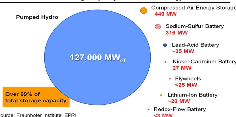
Figure 1. Worldwide installed storage capacity for electrical energy (2010) ... 8
Figure 2. Power to Gas (P2G) integrated with renewable energy ... 13
Figure 3. Schematic diagram of fuel cell system key components. ... 16
Figure 4. Fuel Cell Electrochemistry ... 18
Figure 5. The configuration of fuel cell stack with multiple of single fuel cell components . 19 Figure 6. Basic structure and processes in PEM fuel cell, https://energy.gov/ ... 21
Figure 7. The basic structure and processes in AFC, https://energy.gov/. ... 23
Figure 8. The basic structure and processes in PAFC, https://energy.gov/. ... 25
Figure 9. The basic structure and processes in MCFC, https://energy.gov/. ... 27
Figure 10. The basic structure and processes of the SOFC, https://energy.gov/. ... 28
Figure 11. The basic structure and processes of the DMFC, www.intechopen.com. ... 29
Figure 12. Schematic representation of a typical MFC, https://biologicalfuelcell.com/ ... 32
Figure 13. Schematic diagram of the BioGenerator ... 36
Figure 14. Typical time profile of wind power generation and smoothing to its average value. ... 44
Figure 15. Experimental setup of the trickling bed bioreactor. ... 46
Figure 16. Theoretical change of the substrate (ferrous ion) concentration in time during and after a feed flow interruption. ... 51
ix
interruption. ... 54
Figure 19. Effect of the 16 hours flow interruption on ferrous iron concentration. ... 55
Figure 20. Effect of the 24 hours flow interruption on ferrous iron concentration. ... 56
Figure 21. Effect of the 72 hours flow interruption on substrate concentration. ... 57
Figure 22. The relationship between the parameters th and ts, as described in Fig. 15. ... 58
Figure 23. The relationship between the parameters Sh and ts, as described in Fig. 16. ... 58
Figure 24. The effect of the parameter ts on the reduction of the ferrous iron biooxidation rate... 59
Figure 25. Bioreactor concrete tank dimensional layout ... 79
Figure 26. Plant layout and the process flow diagram of the BioGenerator. ... 85
Chapter 1
1
Introduction
1.1 Renewable Energy
Transformation from the conventional power generation systems towards cheaper,
renewable and environment-friendly resources has been motivating many researchers,
governments and the private sector. There is no doubt that the current energy systems and
technological advancements available in the world are not sufficient to stop the increase
of the concentration of greenhouse gases that are emitted from those resources. We have
to move quickly towards building new technologies and to bring the existing technologies
together to rectify this issue and to get maximum benefit from the entire energy system
including energy production, transformation, to energy transportation and distribution. A
huge effort in this direction will have to be taken at both macro and micro levels.
Energy is critically important to the Canadian economy as Canada is among the largest
energy producers and the highest per-capita energy consumers in the world because of
our climate and resources.
As per Natural Resources Canada [1], electricity in Canada is generated from different
and mixed sources. The electricity generated from natural and renewable resources such
electricity generated from consumed unrenewable resource such as fossil fuels (i.e. coal,
natural gas and oil) is considered secondary energy.
Flowing water is the most important source in Canada, which generates 59.3 per cent of
electricity supply. Canada is considered the second largest producer of hydroelectricity in
the world after China, with over 378 terawatt hours in 2014. The installed hydropower
capacity is more than 78 gigawatts. This capacity has been generated at favorable
geography and hydrography locations, exist primarily in Quebec, but also in British
Columbia, Ontario, Labrador and Manitoba.
The second most important source of electricity in Canada is fossil fuels. Coal has about
9.5 per cent of the generated electricity, while natural gas has the share of 8.5 per cent
and 1.3 per cent goes to petroleum. Fossil fuel generation mostly exists in Alberta and
Saskatchewan. Several power stations are located adjacent to large coal deposits. Fossil
fuel generation is also significant in the Atlantic Provinces, Northwest Territories and
Nunavut. As other provinces, Ontario was depending majorly on coal-fired generation;
but not after April 2014 when the last coal-fired generating capacity was shut down.
The third most important source of electricity in Canada is nuclear power. It counts for
about 16 per cent of generated electricity. Out of the Canada’s nineteen operating nuclear
power plants, eighteen are located in Ontario and one in New Brunswick. Quebec shut
down their nuclear power plant in 2012.
From the non-hydro renewable sources, which contribute 5.2 per cent of the generated
wood waste, spent pulp liquor). However, solar power is still emerging but increasing
rapidly to supply electricity.
As per Canadian Wind Energy Association (CanWEA) [2], Canada is growing fast in
wind power generation, ending year 2015 with more than 11,000 MW of wind energy
capacity, completed 36 wind power supply projects totaling 1,506 MW. At the same year
Canada was the sixth largest market for new wind power supply globally, and presently
has become the seventh largest wind generating capacity in the world.
The 36 wind projects of year 2015 value of $3 billion in investment, were built and
commissioned in Alberta, Saskatchewan, Ontario, Quebec and Nova Scotia. Out of those
projects, 23 have significant ownership stakes from Aboriginal People, municipal
corporations or local farmers.
Referring to the same study [2], the wind power generation is contributing approximately
5 per cent of Canada’s electricity demand, which is the need of more than three million
Canadian homes. This amount of power is supplied by 259 wind farms operating from
coast to coast, including projects in two of the three northern territories.
It is expected that the Canadian wind industry’s performance continues to strong and
stable growth, and there are great opportunities to maximize the economic, industrial
development, and environmental benefits associated with wind energy development.
A recent report from the Global Wind Energy Council (GWEC) [3], has forecasted a
The report also highlighted that the global wind industry has accomplished a record
through year 2015, the total annual capacity installations were 63 GW and made up the
total installed capacity of around 433 GW, presenting 17 % increase over the previous
year. The total investment in new wind power development at year 2015 was almost $
110 billion, which makes the wind power the most popular choice for new power
generation.
GWEC also reported that the overall total installed capacity in Asia is 175.8 GW putting
Asia as the world’s largest regional wind market. However, on national level, China is
the leading with cumulative wind power installations of 145 GW which is greater than all
European Union countries combined with capacity of 141.6 GW. Currently, 28 countries
have a wind power capacity greater than 1 GW installed and eight countries have more
than 10 GW installed.
The report further forecasted future wind capacity in 2050 would vary from a
conservative 2,870 GW under the International Energy Agency’s (IEA) New Policies
Scenario, to its most ambitious 5,806 GW under the GWEC Advanced Scenario.
Under the GWEC Advanced Scenario, wind power is projected to provide at least 36
percent global electricity demand in 2050.
Electricity generated by wind is considered one of the fast-growing source of electricity
worldwide. The wind turbine converts the kinetic energy produced by rotating mills due
to the blow of the wind into an electrical energy. The wind turbines are erected in
installed individually or with a group of turbines to form what it is called “wind farm” or
“wind power plant”. Wind turbine and or wind farm can operate either locally (i.e. off
grid) to serve specific user or community or can be connected to electricity on grid to
serve with other power resources for greater number of consumers. Using wind power is
not only depending on renewable source but also reduces the environmental impact of
generating polluted greenhouse gases (including SOx, NOx, and mercury) and reduce the
dependence on the fossil fuel. However, wind power technology still requires further
research and innovation to improve turbine efficiency, life time, mitigate interconnection
problems, power storage to smooth the power during short supply.
Renewable energy of wind and solar sources have a major drawback which requires
comprehensive consideration in order to be used as a dependable standalone power
generation source. The intermittent, unpredictable and variable rate of supply of both
wind and solar make them unreliable power generation sources. The availability and the
change in intensity of both sources around the day and the year are major problems and
need to find a mechanism to store the abundant energy produced at the peak periods and
use it at the short energy supply periods.
These fluctuations in power supply of renewable sources show the need of a storage
system able to smooth the power generation during the variation of power supply from
either of these two renewable sources.
The storage system solutions, in addition to smoothing the variable power generation of
the renewable sources, also provide low greenhouse gas emissions, support voltage and
1.2
Energy Storage Technologies
Energy storage is a process of capturing an excess energy at a certain times and
store it to be used when it is short or unavailable at different times. Energy comes in
different forms mainly; electricity, chemical, radiation, electrical potential, high
temperature, gravitational potential, mechanical, tidal, and kinetic. Energy storage usually
converts energy of difficult to store forms, such as electrical, into storable forms. Energy
storage technologies vary, some supply long-time storage and the others supply
short-time storage. Pumped hydro energy currently accounts for 99% of the global bulk storage
energy [4]
Lately, the grid electrical power has been mainly depending on burning fossil fuel which
elevates the concern of air pollution, global warming and energy imports. This matter has
evolved the use of renewable energy such as wind and solar power. However, one of the
advantages of the fossil-fuel based electricity generation is the possibility to vary the
power generation to fit the amount of used electricity. Unfortunately, that is not possible
in the case of wind and solar power generation.
The wind power is uncontrolled in a sense that it is unavailable steadily all times. The
intermittent wind power supply makes it unreliable source and effectively needs a storage
backup to replenish the wind power shortage. The same issue occurs with the solar power
Off grid electricity is becoming an effective market segment and is growing fast. An
integrated reliable power source is always a need.
Generally, energy can be stored in wide range of forms, the following are the main and
the most methods of energy storage whether they are natural, commercialized or not:
• Mechanical
o Hydroelectricity dams
o Pumped-storage hydroelectricity
o Compressed air energy storage (CAES)
o Flywheel energy storage
o Gravitational potential energy
• Electrical
o Capacitor
o Superconducting magnetic energy storage (SMES)
• Electrochemical
o Flow battery
o Rechargeable battery
• Thermal
o Brick storage heater
o Cryogenic liquid air or nitrogen
o Eutectic system
o Ice storage air conditioning
o Phase Change Material
o Seasonal thermal energy storage
o Solar pond
o Steam accumulator
• Chemical
o Biofuels
o Hydrated salts
o Hydrogen
o Hydrogen peroxide
o Power to gas
o Vanadium pentoxide
Figure 1 highlights the leading commercialized power storage technologies:
Pumped-storage hydroelectricity
Pumped-Hydro storage technology is considered the largest capacity of active
energy storage, as Electric Power Research Institute (EPRI) [4] reports that PSH has 99%
of bulk storage capacity share. The concept of this technology is to pump the water from
lower level reservoir to higher level reservoir when there is an excess of generated
electricity during lower peaks of demand. However, at times of higher demand the water
at higher reservoir will be released through electricity generator turbine to supply the
required higher demand.
Compressed air energy storage
This technology uses surplus power at lower peak demand to compress air and
store it in cavern or vessel. Once power is needed at higher demand, the air is heated,
expanded and directed through power generator turbine. In addition to energy storage,
this technology had been used in compressed air locomotive inside mines. Intensive
devolvement of this technology came up with a second generation (CAES) with higher
efficiency and lower cost of consumed energy to heat and expand the compressed air.
This technology is expected to have a growing trend in the energy storage industry.
Flywheel energy storage
The concept of flywheel energy storage (FES) is to charge and store energy by
accelerating a rotor to high speed and holding the energy by means of rotational energy.
The rotor is connected to electrical generator which converts the kinetic energy into
spinning speed declines, hence the FES needs to be recharged and increase its rotational
speed. The flywheel is not intended to produce a large amount of energy and is
considered a short duration energy storage. It is well known for its higher efficiency,
longer life time and quicker response.
Lead Acid Batteries
Lead-acid batteries are considered the most commercialized type of rechargeable
batteries in the market. They have wide application including automotive, marine,
telecommunication and many others. At the same time they have major limitations of
their heavy weight and big volume. Their power output is not steady and consistent and
their lifespan varies depending on the application. However, the continuous development
of advanced lead-acid batteries is undergoing to improve its cycle life and durability,
which will lead them to be properly used for peak shaving, frequency regulation, wind
integration, and photovoltaic smoothing.
Sodium-Sulfur Batteries
Sodium-sulfur batteries have the highest capacity among the commercial
rechargeable energy storage batteries. They have applications in electric utility
distribution grid support, wind power integration, and high value service applications.
They are a molten-salt battery type, containing liquid sodium and sulfur. They have high
energy density, high efficiency of charge/discharge and an approximate life time of 15
years. They are a registered trademark of the Japanese NGK Insulators Company. Around
316 MW NaS batteries have been installed globally and this number is expected to
Nickel Cadmium Batteries
Nickel-cadmium batteries are rechargeable type that uses nickel oxide hydroxide
and cadmium as electrodes. Cadmium is a toxic element and the environmental impact
of this type of batteries disposal has contributed significantly to the reduction of its use
and production. In 1990, nickel cadmium batteries lost almost 80% of their market share.
Recently, they were banned from most of the European Union countries and only can be
supplied for replacement purposes or for certain types of new equipment. Presently,
nickel-cadmium batteries have been replaced with nickel-metal hydride batteries.
A metal hydride batteries are also rechargeable and are similar to the
nickel-cadmium batteries using the same positive electrode of nickel oxide hydroxide, but using
hydrogen absorbing alloy instead of cadmium as the negative electrodes. A nickel-metal
hydride battery can have two to three times the capacity of an equivalent size of
nickel-cadmium type, and its energy density can approach that of a lithium-ion battery. In 2008,
more than two million hybrid cars worldwide were manufactured with nickel-metal
hydride batteries.
Lithium-ion Batteries
Lithium-ion batteries are the most popular rechargeable type of batteries used
mainly in electronic products. In Li-ion batteries the lithium ions transfer from the
negative electrode to the positive electrode during discharge and return when charging.
They have a high energy density, small memory effect and low self-discharge. Other than
portable electronic, Li-ion batteries are becoming more popular with electric vehicles,
acid batteries. The high capacity and lower cost of Li-ion battery packs make them
possible to be integrated into systems for grid support applications. Their higher energy
density and lower weight make them an attractive choice for space constraint areas.
Vanadium Redox Flow Batteries
Vanadium Redox Batteries (VRB) are a type of rechargeable flow batteries that
use vanadium ions in different oxidation states to store chemical energy. Vanadium ions
has the ability to exist in one solution in four different oxidation states. This unique
property of vanadium makes it possible for VRB to use just one electroactive element
instead of two, whereas all other types of flow batteries are storing the charge ions in two
separate tanks of electrolytes, one of which stores electrolyte for positive electrode
reaction while the other stores the electrolyte for the negative electrode reaction. Using
one common electrolyte provides potential opportunity to increase cycle life of the
battery.
For their relatively bulky size with other reasons, most vanadium batteries are used for
grid energy storage application. They can be designed to provide energy of 2 to more
than 8 hours, and their cell stacks lifespan is estimated to be around 15 years.
Power to Gas
Power to gas (P2G) is one of the promising power storage technologies that
converts electrical power to a hydrogen gas fuel. It can be deployed as power storage of
wind and solar power generation stations. The surplus power or off-peak power generated
electricity. The excess power is stored by means of hydrogen when using the power to
electrolyze water into hydrogen and oxygen. Hence, stored hydrogen can be converted
into power by utilizing one of three methods.
The first method is to inject the hydrogen into the natural gas grid or to be used in
transport or industry. The second method is to combine the hydrogen with carbon dioxide
and produce methane using a methanation reaction. The third method is to convert
hydrogen to power (gas to power) using thermal engines, fuel cells or the BioGenerator
which will be explained in later chapters. Figure 2 illustrates the concept of integrating
power to gas storage with the renewable energy
source.
1.3
References
[1] Natural Resources Canada, http://www.nrcan.gc.ca/home
[2] Canadian Wind Energy Association (CanWEA), http://canwea.ca/
[3] Global Wind Energy Council (GWEC), http://files.gwec.net/, (Global Wind
Energy Outlook 2016)
[4] ELECTRIC POWER RESEARCH INSTITUTE, A White Paper Primer on
Applications, Costs, and Benefits (Electricity Energy Storage Technology
Chapter 2
2
Literature Review
Recent technology advancement has put the power-to-gas as potential power
storage option that can be integrated with the renewable power generation. In this
method, excess or off-grid electricity is used to split water into hydrogen and oxygen by
means of electrolysis. The produced hydrogen is stored and later can be used to generate
power by different ways; it can be mixed with natural gas and burned in turbines, it can
be combined with carbon dioxide to produce methane, or can be used directly for
re-electrification using fuel cells.
2.1
Fuel Cells Technology
The principle of fuel cell was invented in 1839 by the Welsh lawyer Sir William
Robert Grove [5]. Sir W. Grove was examining the reverse process of water electrolysis
by combining hydrogen and oxygen to produce water, before he noticed electricity
generation due to this catalyzed by platinum reaction.
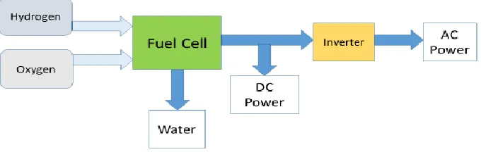
Fuel cell is simply a device that converts the chemical energy from a fuel into electricity
combined producing electricity, heat, and water. Figure 3 shows the key system
components of fuel cell for producing AC or DC power.
Figure 3. Schematic diagram of fuel cell system key components.
In general, the fuel cell is a battery, in which the fuel, oxidant and their product(s) are all
fluids, and can be continuously fed or removed from/to the cell. Therefore, fuel cell
works as long as it is fed with fuel and oxidant. Fuel cells can have quite a high energy
conversion efficiency, up to 60%. Although fuel cells have great potential advantages, it
was not until the 1950s in response to the needs of the US space program that practical
devices were developed.
Though their basic principle looks simple, producing fuel cells as a practical product
involves many engineering challenges and so far the proposed solutions are not cost
effective. Even after several decades of research and development, today there is still no
applications, while some major production is used for research and development labs
over the world.
Fuel cells are different from combustion engines, as they work on the “cold combustion”
principle. There are several different types of fuel cells, they differ in their fuels,
operating temperature and other conditions. They use relatively highly efficient
electrochemical processes and don’t cause mechanical wear and tear to their components.
The most popular type of fuel cells is the proton exchange membrane (PEM) fuel cell
also called the polymer electrolyte membrane fuel cell. It uses hydrogen as the fuel and
oxygen usually from air as the oxidant.
The overall PEM fuel cell reaction is:
2H2 + O2⇒ 2H2O (2.1)
The fuel cell consists of two electrodes; anode and cathode, separated by a polymer
electrolyte membrane allowing only protons to pass through and get transferred from the
anode to the cathode. Two different half reactions occur in the fuel cell, each of the half
reactions occurs at different electrode of the fuel cell, both reactions comprise the overall
reaction and produce electricity and heat, as shown in equations 2.2, 2.3 and 2.4:
Anode (-): ½ H2 (g) → H+ (aq) + e- , E0 = 0 V (2.2)
Cathode (+): ½ O2 (g) + 2H+ (aq) + 2 e- → H2O (l or g) , E0 = + 1.23 V (2.3)
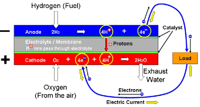
Figure 4. Fuel Cell Electrochemistry
Figure 4 illustrates the fuel cell half reactions at the individual electrodes. The electrodes
are made from porous carbon which allows the active gases to pass through and the
electrode surfaces are inked with platinum catalyst to accelerate the reactions. The
electrolyte is a thin sheet of cation ion exchange polymer about 50 microns thick which
permits the passage of hydrogen ions and doesn’t conduct electrons.
As shown in Figure 4 and reaction 2.2, the hydrogen is oxidized at the anode and loses its
electron in the process. The proton (the positive hydrogen ion) passes through the
electrolyte membrane to the cathode while the electron travels around the external circuit
to the cathode.
The oxygen which is supplied to the cathode, is reduced by reacting with the electrons
electrons travel from the anode to the cathode via external circuit represent the
conventional electrical current flowing in the opposite direction.
The rate of oxidation at the anode and the rate of reduction at the cathode in some types
of fuel cells are very slow, therefore, catalysts are used to increase the rate of these
reactions at lower temperatures. Alternatively to avoid the cost of expensive catalysts,
some fuel cells are designed to operate at higher temperatures. In PEM and some other
fuel cells, platinum catalyst is used. Unfortunately, it is very expensive and sensitive to
poisoning by very small amounts of carbon monoxide, which requires additional
purification processes to eliminate potential contamination from the system.
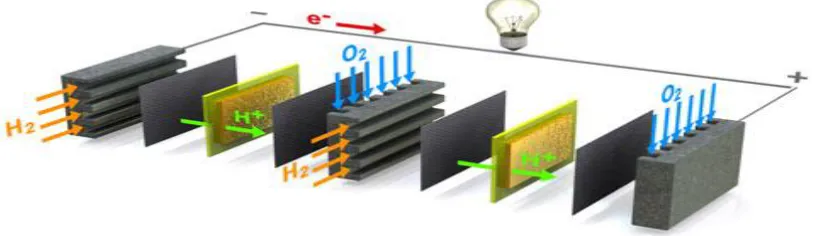
Single H2/O2 fuel cell usually produces low voltage (0.6-0.7 Volt) which means that the
system needs a certain number of cells connected in series (a stack) to obtain the required
voltage. Therefore, the potential generated power can be obtained by assembling different
number and size of individual fuel cells to comprise the stack and the surface area of the
unit. Figure 5 illustrates the configuration of fuel cell stack with multiple cells.
Figure 5. The configuration of fuel cell stack with multiple of single fuel cell
2.2
Fuel Cell Types
Basic fuel cell operation has many challenges which led the researchers to come up
with range of fuel cell designs using different basic chemistry. These fuel cell types have
been developed to meet different design or operating criteria such as less expensive
construction, more efficient fuel utilization, faster start-ups or the use of more convenient
or less expensive fuels. Higher power outputs can be achieved by operating at higher
temperatures, by using catalysts to accelerate the fuel cell electrochemical reactions and
by using electrodes with a greater surface area.
2.2.1 Conventional Fuel Cells
Currently there are six major fuel cell types being developed for different
applications. Some of these fuel cells operate at high temperatures and some use unique
electrode materials or catalysts:
- Proton Exchange Membrane Fuel Cell
- Alkaline Fuel Cell
- Phosphoric Acid Fuel Cell
- Molten Carbonate Fuel Cell
- Solid Oxide Fuel Cell
These fuel cells have been proposed for a wide range of applications from powering
laptop computers, through automotive transportation to high power load levelling.
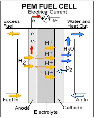
Proton Exchange Membrane Fuel Cell
Proton exchange membrane (PEM) fuel cells need hydrogen and oxygen from the
air to operate. They use solid polymer as an electrolyte and porous carbon electrodes
containing platinum or platinum alloy catalyst. As illustrated in Figure 6, the hydrogen
gas is oxidized on the anode splitting into a proton and electron, only the proton passes
through the polymer electrolyte membrane from the anode to the cathode. The electron
travels through external electrical loop from the anode to the cathode generating the
electrical current. At the cathode the migrated proton along with the electron reduce the
oxygen to water forming the overall reaction product and generating electricity and heat.
PEM fuel cells deliver high power density and have the advantages of low weight and
volume compared with other fuel cells. They are typically fueled with pure hydrogen.
PEM fuel cells operate at relatively low temperatures, around 80°C (176°F), cold start
below 0°C is also proven. Low temperature operation allows them for quick start (less
warm-up time) and leads to less wear on system components hence better durability.
However, a noble-metal catalyst (typically platinum) is required as an electrocatalyst at
both electrodes to accelerate the rate of both half reactions, the use of expensive metal
results in high cost of the system. Moreover, the platinum catalyst is extremely sensitive
to carbon monoxide poisoning, which entails the necessity of employing an additional
unit to remove carbon monoxide from the fuel gas if the hydrogen is derived from a
hydrocarbon fuel, which means another cost increment.
However, PEM fuel cells have a good combination of efficiency, power output and low
operating temperature make them among other types, the best choice for automotive
applications. Currently, PEM fuel cells are used primarily for transportation applications
and some stationary applications. Due to their fast start-up time and favorable
power-to-weight ratio, PEM fuel cells are particularly suitable for use in passenger vehicles, such
as cars and buses. The rated power density of the PEMFC of 0.7 W.cm-2 and higher is
attainable depending on operating conditions.
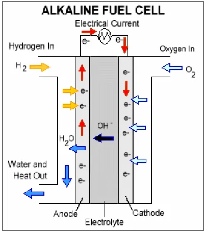
Alkaline Fuel Cell
Alkaline Fuel Cells (AFC) need oxygen from the air and hydrogen to operate as in
the case of PEM fuel cells. They use aqueous solution of potassium hydroxide as an
electrolyte. Figure 7 illustrates the basic structure and processes in the AFC. The
operating temperature is usually around 80°C, but can be as high as 200°C, at higher
Figure 7. The basic structure and processes in AFC, https://energy.gov/.
They were some of the earliest practical fuel cells and were used in the US space program
for producing drinking water and generating electricity on-board of spacecraft. AFCs are
usually not using platinum catalyst on their electrodes, but instead they use a variety of
non-precious metals as a catalyst at the anode and cathode. Therefore, they are less
expensive compared with PEM cells and have a relatively high operating efficiencies of
60%. Unfortunately conventional AFCs are facing many challenges affecting their
performance, reducing their power output and shortening their lifetime such as shunt
currents, wettability, corrosion, difficulty in handling differential pressure across the
electrolyte. The most important challenge for this fuel cell type is that it is susceptible to
poisoning by carbon dioxide. In fact, even a very small amount of CO2 in the air can
dramatically affects cell performance and durability due to carbonate formation in the
To overcome the challenges of conventional AFC, recently a novel AFC that uses a
polymer membrane as the electrolyte instead of potassium hydroxide liquid has been
developed. It is closely related to conventional PEM fuel cell, except that they use an
alkaline membrane instead of an acid membrane.
Alkaline membrane fuel cells (AMFCs) address some of these concerns and have lower
susceptibility to CO2 poisoning compared with liquid-electrolyte AFCs. However, CO2
still affects performance of AMFCs, and performance and durability of the AMFC are
still lower than that of PEMFCs. AMFCs still have challenges including tolerance to
carbon dioxide, membrane conductivity and durability, higher temperature operation,
water management, power density, and anode electro-catalysis.
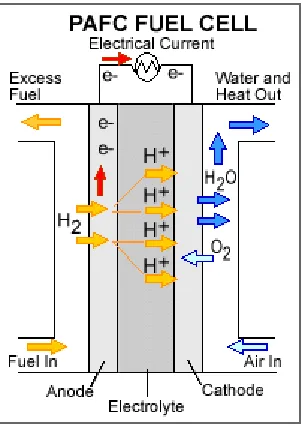
Phosphoric Acid Fuel Cell
Phosphoric Acid Fuel Cells (PAFC) also need hydrogen and oxygen from the air
to operate. PAFCs use phosphoric acid as an electrolyte, the acid is contained in a
Teflon-bonded silicon carbide matrix and both electrodes, anode and cathode, are made of
porous carbon containing platinum catalyst. The basic structure and the electrochemical
reactions that take place in the cell are shown in Figure 8.
They run at high temperatures of around 220°C and can deliver high power of a
Megawatt range but have relatively low efficiency of around 37-42%. The power density
of the PAFC is in the range of 0.14 W.cm-2. However, due to the poor conversion
be recovered using combined heat and power (CHP) applications, hence improving the
system efficiency.
Figure 8. The basic structure and processes in PAFC, https://energy.gov/.
The PAFC is always considered the first generation of modern fuel cells. This type of
fuel cell is typically used for stationary power generation, but some PAFCs have been
used to empower large vehicles such as city buses.
Compared with PEM fuel cells, PAFCs are considered more tolerant to impurities which
come with hydrogen when reforming fossil fuels. Although PAFCs are more than 85%
efficient when used for the co-generation of electricity and heat, they are less efficient at
generating electricity alone (37%–42%). So, when compared with other fuel cells, PAFCs
are considered less powerful than others, having the same weight and volume. As a
result, PAFCs are not only large and heavy but are also expensive. They require much
higher loadings of expensive platinum catalyst than other types of fuel cells do, which
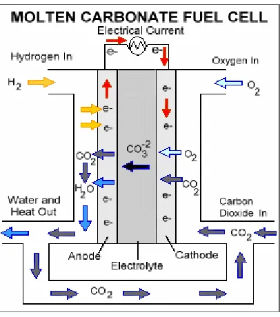
Molten Carbonate Fuel Cell
Molten Carbonate Fuel Cells (MCFC) also need hydrogen and oxygen to operate.
MCFCs are high temperature fuel cells that use an electrolyte composed of a molten
carbonate salt mixture soaked in a porous, chemically inert ceramic lithium aluminum
oxide matrix. MCFCs run at higher temperatures of 650°C to 1000°C. Because they
operate at high temperature, no precious metals are used as catalysts at the anode and
cathode. Their achieved efficiencies can reach 45% or more and power outputs of over 1
Megawatt are typical in grid supply applications. The power density of the MCFC is in
the range of 0.1 – 0.12 W.cm-2. The basic structure and the electro-chemical reactions
that take place in the MCFC are shown in Figure 9.
Under the high temperatures at which MCFCs operate, methane and other hydrocarbons
are internally reformed inside the fuel cell and converted into hydrogen and carbon
dioxide, so there is no need for external reforming process to supply the fuel cell with
pure hydrogen as in the cases of alkaline, phosphoric acid and PEM fuel cells. This
shortcut process results in a major reduction of MCFCs cost when compared with other
fuel cell types. MCFCs are currently under development to be fueled by natural gas and
coal for use in power plants, various industries and military applications.
MCFCs have improved efficiency over PAFCs. They can reach 65% efficiencies when
coupled with a turbine, and when capture and use the wasted heat, overall fuel
Figure 9. The basic structure and processes in MCFC, https://energy.gov/.
While the high temperature operation of MCFCs have the advantage of eliminating the
external reforming process, their disadvantages include the reduced durability of the
MCFCs, along with the highly corrosive nature of the electrolyte, both of which decrease
the fuel cell life time. However, extensive studies are exploring corrosion resistant
materials and fuel cell designs that improve the performance and prolong the cell
lifetime.
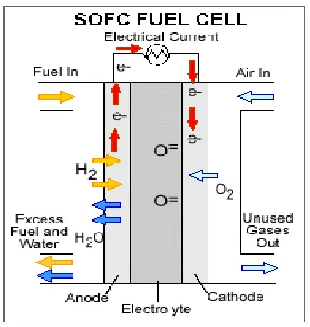
Solid Oxide Fuel Cell
Solid Oxide Fuel Cells (SOFC) need hydrogen and oxygen from the air to
operate. SOFCs also operate in the same or even higher temperature range as the MCFCs
(800 to 1,000°C). They use a rigid, non-porous ceramic compound as an electrolyte
which can stay solid at high operating temperatures. SOFCs can deliver power of several
when the system's waste heat can be utilized (co-generation), the overall fuel efficiency
can reach 85%. The power density of the SOFC is in the range of 0.15 – 0.7 W.cm-2. The
basic structure and the electro-chemical reactions that take place in the SOFC are shown
in Figure 10.
Figure 10. The basic structure and processes of the SOFC, https://energy.gov/.
Since the SOFCs operate at very high temperatures, they have the advantage of not using
precious metal catalyst at the electrodes. As in the case of MCFCs, the high temperatures
at which SOFCs operate, allows SOFCs to reform a variety of fuels internally inside the
fuel cell, eliminating the need of external reforming. This would also result in the major
reduction of the cell and operation costs.
SOFCs are the most sulfur-resistant fuel cell type; they are also not poisoned by carbon
monoxide. This feature allows SOFCs to use different types of fuels like natural gas,
biogas, and gases produced from coal and organics gasification. As in the case of
MCFCs, the high temperature operation has also disadvantages. It causes a slow start-ups
applications to utility power generation and not for transportation. The high operating
temperatures also affect negatively the durability of the cell and development of low cost
materials with higher durability is a technical challenge for this technology.
Direct Methanol Fuel Cell
Direct Methanol Fuel Cells (DMFC) are similar to PEM cells but they use
methanol instead of pure hydrogen and oxygen from the air to operate. They work at low
temperatures of 50°C to 100 °C. Maximum obtained power densities are around 0.25
W.cm-2. All other types of fuel cells are powered by hydrogen whether it is fed directly or
generated inside the fuel cell by internal reforming of hydrogen of fuels such as
hydrocarbon fuels. However, DMFCs are powered by pure methanol which is usually
mixed with water and fed directly to the anode side of the fuel cell. Using such
inexpensive liquid fuel avoids both the hydrogen supply challenges and the requirement
of external or internal reformer. The basic structure and the electro-chemical reactions
that take place in the DMFC are shown in Figure 11.
Methanol has a higher volumetric energy density than hydrogen and since it is in the
liquid form at ambient temperatures, makes it much easier to be transported and stored
compared with the gas fuels used in other fuel cells. DMFCs are mostly used for low
power applications such as portable electronics.
Table 1 classifies the different types of fuel cells based on their operating temperatures,
type of fuel and used electrolyte.
Table 1. Classification of Fuel cells based on operating temperatures, used fuels and
electrolytes
Operating Temp. (°C)
Fuel
Electrolyte
PEMFC
40-90
H2
Polymer
AFC
40-200
H2
KOH
PAFC
200
H2
Phosphoric Acid
MCFC
650
CH4,H2
Molten Carbonate
SOFC
600-950
CH4,H2
Solid Oxide
DMFC
60-130
Methanol
Polymer
2.2.2 Biological Fuel Cells
Biological fuel cells have been investigated since it was discovered that many
biological pathways have bio-electrochemical side, which proved that biological reaction
may induce an electrical action [6].
There are different biological mechanisms that can be utilized to operate biological fuel
cells, including:
1- Microbial cells that deploy biochemical path to convert a primary organic fuel into
a secondary fuel such as hydrogen or ethanol. This biological process can be used
within a conventional fuel cell to supply it with its fuel [6].
2- Microbial cells that convert chemical energy directly into electrical energy by
oxidizing an organic fuel (i.e. glucose) using proteins, enzymes or
microorganisms. The generation of power is directly by biological means [7 and
6].
3- Microbial cells that combine both the utilization of photo-chemically active and
biological systems to collect the energy from sunlight and convert it into electrical
energy [8, 9 and 10].
In general, biological fuel cells can convert the energy of the biochemical oxidation of
organic or inorganic substrates directly into electrical energy, allowing to generate
electricity from electro-chemically passive compounds [11].
The biological and chemical fuel cells have similar basic principles. The biological fuel
cathode. The biocatalyst at the anaerobic anodic chamber could be either enzyme or
whole microbial cell. This biocatalyst oxidizes the fuel which could be organic matter
producing electrons and protons. These protons migrate through a selective membrane
(electrolyte) separating the anodic from the cathodic chambers which allows the protons
only to pass through to the cathode. The electrons travel via an external circuit loop
connecting the anode with the cathode generating the electrical current. At the cathode
the electrons and the protons combine with the oxygen to form water [12]. Figure 12
illustrates the components of the microbial fuel cell.
Figure 12. Schematic representation of a typical MFC, https://biologicalfuelcell.com/
The biological fuel cells can be also classified into two main types based on the used
biocatalyst - enzymes or whole microbial cells. Enzyme biocatalysts are expected to
increase the conversion rate of substrate, to facilitate the maintenance of the set, and to
the case of microbial fuel cells, MFC) is preferable to enzymes, because of their specific
features. Microorganisms oxidize wide range of substrates so they can be used with
various organic fuels, and they are not easily poisoned and lose their activity under
normal operation conditions as in the case of enzymes. Furthermore, the cost of
microorganisms is much lower than of enzymes as the latter require special production
and purification manufacturing processes [13].
Nevertheless, In the case of microbial fuel cells, microorganisms play a significant role as
they are responsible for the bioconversion of the fuel by splitting it into protons and
electrons; they also can contribute to the electrons transfer to the anode. There have been
many studies that focus in using microbial cells in the fuel cell to oxidize the fuel in the
anode and to catalyze the reduction of oxygen in the cathode [7].
A variety of microorganisms, both axenic (pure) and mixed cultures of anaerobic or
facultative species are currently used as biocatalysts in microbial fuel cells. The mixed
cultures are preferable to the axenic ones due to their important advantages. Mixed
cultures have a higher resistance against process disturbances, larger substrate versatility
and a higher power output [13].
According to thermodynamics, the maximum voltage generated by a single MFC is
around 1V, while the practically obtained maximum voltage is 0.8V. In order to obtain
higher voltages, the cells have to be arranged in series (stacks). The reported so far
current generated by MFCs has not exceeded 0.1A. The average power density of a single
power densities of 250 W/m3, implying that improvements in MFC performance are
under way.
However, despite the great advancement in recent years in this research field, MFCs are
still suffering significant hurdles for their large scale implementations. The major
obstacles are due to the insufficient performance with both anodic and cathodic electron
transfer, upscale technical issues and high investment costs.
2.3
BioGenerator
The BioGenerator is a unique invention meant to generate electricity by converting
chemical energy hydrogen oxidation into electrical energy. It uses to a certain degree the
concept of PEM fuel cell, as they share the same anodic reaction of oxidizing the
hydrogen gas into protons and electrons, equation 2.2. The protons as in the case of
PEMFC migrate through a selective membrane (i.e. proton exchange membrane) from
the anodic chamber to the cathodic chamber.
However, the cathodic reaction of the BioGenerator is different from the one of PEMFC.
In the BioGenerator on the cathode, the ferric iron (Fe3+) is reduced to ferrous iron (Fe2+)
by receiving the electrons produced at the anode which travel via external loop from the
anode to the cathode generating the electrical current, the BioGenerator cathodic reaction
Cathode (+): Fe3+(eq) + e- → Fe2+ (aq), E0 = + 0.77 (2.5)
By comparing the above cathodic reaction of the BioGenerator with the one of other fuel
cells, the BioGenerator is not similar to any of the six conventional fuel cell types that
mentioned in the previous section, and neither to the known microbial fuel cells.
Technically, the BioGenerator is comprised of two main parts; electrochemical stack and
bioreactor.
The electrochemical stack is a unit that has the same concept as the fuel cell. It has two
electrodes (i.e. anode and cathode) separated by selective proton exchange membrane.
Both electrodes are made of porous carbon material and the proton exchange membrane
has the same function of the one of PEM fuel cell.
In order to generate continuous power supply, both hydrogen gas and ferric iron in
aqueous solution have to be continuously fed to the electrochemical stack unit to assure
both anodic and cathodic half reactions are continuously progressed and the electrons are
continuously flowing from the anode to the cathode generating electrical current.
At the cathode as shown in equation 2.5, the ferric iron is continuously reduced to ferrous
iron and in order to feed the electrochemical stack with continuous supply of ferric iron
aqueous solution, the ferrous iron has to be oxidized to ferric iron. This process is
accomplished biologically in a separate bioreactor which is the second main part of the
Figure 13. Schematic diagram of the BioGenerator
In the bioreactor, the actual and complete half cathodic reaction takes place. Ferrous iron
bio-oxidizing microbial culture is mobilized in the bioreactor as either attached or
suspended culture. The function of this microorganisms is to oxidize the ferrous iron into
ferric iron, so the liquid medium in the bioreactor which contains high concentrations of
ferric iron as an aqueous solution is pumped to the cathodic chamber of the
BioGenerator’s electrochemical stack unit. The aqueous solution of ferrous iron and
protons that passed through proton exchange membrane from the anodic chamber to the
cathodic chamber, are then returned to the bioreactor. The bioreactor is also supplied with
air from which the dissolved oxygen reacts with protons completing the cathodic half
reaction as shown in the following equation:
After combining reactions 2.2 and 2.6, the overall net reaction in the BioGenerator is:
H2 + ½O2 = H2O + Q (2.7)
Most of the energy of hydrogen oxidation (Q=142 MJ / kg) is converted to electrical
energy. In addition, approx. 30% of the energy of reaction 2.6 is released as waste heat,
while 7% is used by microorganisms for microbial growth and maintenance.
The main role of the bioreactor is to transfer the chemical energy of oxygen to ferric ions
(reaction 2.6) by re-oxidizing ferrous to ferric iron.
The rate of reduction of ferric iron at the cathode (2.5), which under steady state
conditions is equal to the rate of ferrous iron oxidation in the bioreactor (2.6) are both
proportional to the electrical current (i.e. the rate of flow of electrons shuttled between
reactions 2.2 and 2.5) drawn from the BioGenerator.
Ferrous iron oxidizing microorganisms (IOM) are class of microorganisms which in
nature are responsible for the formation of acid mine drainage. IOMs are mainly
autotrophic and mixotrophic types of bacteria which live in media having wide range of
temperatures, reaching 500C and a pH as low as zero. These different types of bacteria
oxidize ferrous iron into ferric iron. They are mainly autotrophic, use carbon dioxide as
the carbon source and oxygen as the electron acceptor.
The main iron oxidizing microorganisms are Thiobacillus ferrooxidans, Leptospirillum
ferriphilum, and Cyanidium caldarium. Each of these species dominate at certain
optimum media temperature and pH, also each of these species have different iron
growth of Leptospirillum ferriphilum occurs at 40-450C and pH 0.7-1.5 [9]. Different
types of bioreactors can be used in the BioGenerator, where the airlift was used initially
for the bench scale and later for the pilot plant BioGenerator. Later a trickling bed
bioreactor was used as bench scale for some test studies.
In both bioreactor types, close to optimum microbial culture growth conditions need to be
maintained. The bioreactor temperature has to be kept at 40-450C and the pH at 0.7 to
1.2. In the case of airlift bioreactor which relies on bubbling air supply, adequate air flow
rate has to be maintained to assure that the required amount of oxygen according to
equation 2.6 has been transferred to the bioreactor liquid. Oxygen mass transfer is usually
the limiting factor of the power generation in the entire BioGenerator. Nevertheless, in
the case of trickling bed bioreactor which relies on circulating the bioreactor liquid to
diffuse the oxygen from the atmosphere, all mass transfer parameters should be
considered while calculating the circulation flow rate to assure the exact required oxygen
quantity has been dissolved in the bioreactor liquid.
2.4
BioGenerator Challenges
As any emerging technology, BioGenerator has many areas that need further
investigation and development to reach commercial stage.
As previously mentioned the BioGenerator comprises of two main components;
continuously receives bioreactor liquid with pH in the range of 0.7 to 0.9 and temperature
of around 400C, this liquid contains high concentration of ferric ions that can reach 50
g/L.
One of the by-products of the microbial iron oxidation is jarosite [10], which is an
insoluble basic that can plug the pores of the cathode. Therefore, the minimization of
jarosite formation is highly desired. The complete elimination of the jarosite formation
can be achieved by bringing the pH in the bioreactor to below 0.9.
The other main element of the BioGenerator is the bioreactor. Supplying the required
amount of oxygen is the most important power consumption element in the
BioGenerator. In order to increase the electricity output of the BioGenerator, higher
concentration and flow rate of ferric ions have to pass through the electrochemical stack
unit and the reduced ferric ions into ferrous ions in the cathodic chamber are delivered to
the bioreactor to be biologically re-oxidized once again into ferric ions. From the
stoichiometric relationship of equation (2.6), 1 g of oxygen is needed to react with 7.4 g
of ferrous ions which when calculating the actual oxygen transfer rate (AOTR) turns to
huge amount of oxygen needed to be transferred to the bioreactor liquid. Reducing the
required amount of air to transfer the same amount of oxygen is a very important factor to
reduce the operational cost of the BioGenerator and increase the energy efficiency of the
amount of generated electricity compared to the amount of consumed electricity.
Improving the oxygen transfer rate and reducing the running cost of the BioGenerator
leads us to investigate different types of bioreactor designs and configurations. This was
the main reason of researching the dynamics of trickling bed bioreactor type and compare
design, there are many other parameters that can improve the oxygen transfer efficiency,
just like the type of air diffuser used, the depth of the liquid inside the bioreactor, and the
temperature of the liquid.
Ferrous iron oxidation rate is another main factor that can play major role in reducing the
volume of the bioreactor and the capacity and size of the auxiliary equipment, piping and
fittings required for the process. More studies need to be conducted on various iron
oxidizing species by varying the reaction parameters and study their effects on ferrous
iron oxidation rate.
Furthermore, an economical studies are also needed to give more factual idea of both
capital and operational costs of large scale BioGenerator for commercial comparison with
other power storage options. However, this study was conducted and presented in chapter
2.5
References
[1] Webb, K. R. "Sir William Robert Grove, (1811-1896) and the origins of the fuel
cell." Journal of the Royal Institute of Chemistry 85 (1961) 291-293.
[2] F. Davis, S. P. J. Higson, Biofuel cells—Recent advances and applications.
Biosensors and Bioelectronics 22 (2007) 1224–1235
[3] R.A. Bullen, T.C. Arnot, J.B. Lakemanc, F.C. Walsh, Biofuel cells and their
development,Biosensors and Bioelectronics 21 (2006) 2015–2045
[4] T. Yagishita, S. Sawayama, K. Tuskahara and T. Ogi, Effects of intensity of
incident light and concentrations of Sunechococcus and 2-Hydrodxy -1, 4-
Naphthoquinone on the current output of photosynthetic electrochemical cell, Solar
Energy Vol. 61, No. 5, (1997) pp. 347–353.
[5] S. Tsujimura, A. Wadano, K. Kano, T. Ikeda, Photosynthetic bio-electrochemical
cell utilizing cyanobacteria and water-generating oxidase, Enzyme and Microbial
Technology 29 (2001) 225–231.
[6] Linda de la Garza, G. Jeong, P. A. Liddell, T. Sotomura, T. A. Moore, A. L.
Moore, and D. Gust, Enzyme-Based Photo-electrochemical Biofuel Cell, The Journal
of Physical Chemistry B 107 (2003), 10252-10260.
[7] Varfolomeev, S.D., Krylova, L. & Zaikov, G.E. (eds) 2008, Molecular and
[8] A.K. Shukla, P. Suresh, S. Berchmans and A. Rajendran, Biological fuel cells and
their applications, Current Science, Vol. 87, No. 4 ( 2004), P 14.
[9] K. Penev. D. Karamanev, Batch kinetics of ferrous iron oxidation by
Leptospirillum ferriphilum at moderate to high total iron concentration, Biochemical
Engineering Journal, Volume 50, Issues 1–2, (2010) 54–62
[10] J. Daoud, D. Karamanev, Formation of jarosite during Fe2+ oxidation by
Chapter 3
3
Study of the Dynamics of Ferrous Iron
Biooxidation by
Leptospirillum ferriphilum
in
a Trickling Bed Bioreactor Used for Energy
Storage
3.1
Introduction
The use of energy storage technologies is probably the best way to solve the
problem of power variability. One of the most promising ways to store electrical energy
is based on the use of hydrogen as an intermediate storable energy vector. The
hydrogen-based energy storage contains three main components: electrolysis of water during a peak
renewable power generation, storage of the produced hydrogen, and re-electrification of
the stored H2 back to electricity during a low renewable power generation. While both the
water electrolysis and hydrogen storage are relatively well developed, there is currently
no reliable commercial technology for the re-electrification of hydrogen, i.e. for the
conversion of hydrogen to electricity. The recently invented technology named
BioGenerator [1] is a unique, commercially-viable electro-bio-chemical process for the
conversion of hydrogen to electricity, as explained in the previous section 2.3.
In the hydrogen-based energy storage, the convertor of hydrogen to electricity is turned
on mostly during the periods of reduced wind or solar power generation or of their
the low wind or solar power generation, while they are idle during high renewable power
generation (sunny and/or windy periods). Figure 14, illustrates the sequential time profile
of the BioGenerator operation.
Figure 14. Typical time profile of wind power generation and smoothing to its
average value.
1 – Excess wind generation: electrolyzer on, BioGenerator off; 2 – low wind power
generation: electrolyzer off, BioGenerator on.
Trickling bed bioreactor is a type of bioreactors considered to be used in the
BioGenerator for its beneficial characteristics compared to other bioreactor types. The
main advantage of trickling filters is the low energy consumption and high oxygen
transfer rate.
The main idea of trickling bed bioreactor is circulating the bioreactor solution liquor to
assure dissolving the required oxygen for iron oxidation reaction and growth of
bioreactor and in the same time increases the residence time inside the bioreactor tending
for higher iron oxidation rates.
The main aim of this work is to study the bioreactor behavior during and after
interruptions of the substrate (ferrous iron) delivery. The main question to be answered
whether the microbial activity is influenced by interruptions in the substrate supply,
which is expected during the operation of the bioreactor as part of the BioGenerator.
3.2
Materials and Methods
3.2.1 Description of Experimental Setup
The experimental setup used in this work is shown in Figure 15. The experiments
were performed using two trickling bed bioreactors with a shape of vertical cylinders.
They had an internal diameters of 9 cm and a total height of 70 cm. Each of the
bioreactors has a perforated plastic plate (8 cm holes) fixed at 6.6 cm above the bottom of
the bioreactor. Above the plate, the bioreactors were separated by a vertical plexi-glass
plate (30 cm high) into two equal compartments. One of these compartments was filled
with plastic biofilm support.
The liquid medium, trickling over the plastic support, was collected below the perforated
plate. The volume of liquid below the plate was maintained at approximately 0.410 L.
(Thermo Fisher Scientific, model 7523-70) which was drawing liquid from the space
below the perforated plate. The flow rate of the circulating liquid was 100 mL/min. A
second peristaltic pump (Thermo Fisher Scientific, model no. 7521-50) was used to
provide each bioreactor with feed solution containing ferrous sulfate and a nutrient
solution (9K) with feed rate of 0.4 mL/min. A second channel of the same pump was
used to withdraw the spent solution from the bioreactors by means of a fixed drain
suction tube installed on top level of the liquid under the perforated plate. The feeding
rate was higher than the evaporation rate.