Available online:
http://edupediapublications.org/journals/index.php/IJR/
P a g e | 1253Analysis of a Stacked Patch Antenna with Integrated Slots
K.Y.K.G.R. Srinivasu
1
PG Scholar, Vignan’s Institute of Information Technology, Visakhapatnam.
Abstract:
Microwaves antennas are being extensively used in multiple communication related applications. Out of which microstrip patch antennas are on the top of the ladder, because of its low profile, ease of installation and its compatibility with radio frequency devices. The paper deals with the design of an edge fed microstrip stacked patch antenna with integrated slots and the frequency of operation is C-band. The attributes such as impedance bandwidth, standing wave ratio, directivity and gain are observed for the stacked patch antenna with integrated slots and compared the same without stacked patch. Rogers RT Duroid 5870 is used as the substrate material for the antenna, with a dielectric constant of 2.33 and transmission line model equations are considered for determining the dimensions of the design. The above mentioned design is simulated using CST microwave studio.
Keywords
Microstrip edge fed, Stacked Patch, Rogers RT Duroid 5870, Impedance bandwidth, Transmission line model equations.
1. Introduction
Antennas role in communication systems is incomparable. It is a device used to convert Radio frequency signal into an Electromagnetic wave in free space [1]. In case of microstrip patch antenna, both the conducting element and the ground plane are geometrically located on either side of the dielectric material [2].
Any conducting materials can be used as a patch and it can be of any shape like, rectangular, circular or square type [3]. Microstrip feed, coaxial feed, proximity coupling and aperture coupling are the feeding techniques of an antenna. Among those proximity coupled feeding is a tedious one[4].
The proposed antenna is designed using microstrip feed line. Microstrip technology antennas are more advantageous when compared to the conventional aerials.
These are less expensive, small in weight, low volume and easy to integrate with devices. The microstrip patch antennas are an individual choice. These are helpful in Satellite communication, wireless communications, medical and military systems [5].It consists of narrow bandwidth, low efficiency and low gain. There are several methods to improve these parameters by changing the slots
and applying stacked patches to the original patch, fractal geometry [6].
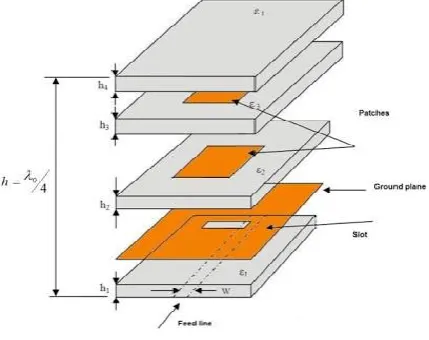
In this paper, twin slots are placed on the patch and stacked patch is introduced with 3mm air gap above the original patch to increase the Return Loss (S11), gain and directivity.
2. Stacked Patch Antenna
The Dielectric substrate and a ground plane is present on the either side of the plane and a radiating patch is kept on the top of the substrate and it is of any shape (planar or non planar in geometry) [7].
It is a resonant antenna and is popularly printed for narrow band microwave wireless links that are required for semi hemispherical coverage [8]. It is utilized as elements for an array due to its ease of integration and planar configuration with micro strip technology [9]. Most commonly used micro strip antennas consists of rectangular and circular patches and are used for most demanding applications [10]. The Symmetric pattern of radiation is the main advantage of circular patch antenna [11].
Stacked patch antenna is configured of multiple substrate materials with same or different dielectric constant. Air gap is maintained between each element. The designed transducer comes under the category of fractal antennas, which is the appreciable way to enhance the parameters. Each dielectric element have its own dimensions, the physical length of the antenna can be determined by considering its wavelength λ0. The separation gap between is a function of wavelength and it is equal to the one fourth of its operating wavelength.
Available online:
http://edupediapublications.org/journals/index.php/IJR/
P a g e | 1254Figure 1. Stacked patch edge fed microstrip patch antenna
3. Design Procedure
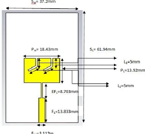
The Edge Fed Microstrip Patch Antenna (EFMSPA) and Edge Fed Microstrip Stacked Patch Antenna (EFMSSPA) with twin slots are shown in Figure 2 and Figure 3.
The design process of an EFMSPA is obtained by using FR4 Epoxy having a dielectric constant of 4.3. The thickness of the substrate is 1.6mm. The Length and Width of the Substrate are 61.9mm of 37.2mm. The Patch and Ground thickness is 0.2mm and the material for the Patch and Ground is Copper. The parameters are shown in the Table 1.
The design of an antenna is done in two ways to get the better gain and directivity. Figure 2 shows EFMSPA with twin slots. Figure 3 shows Edge Fed Microstrip Stacked Patch Antenna (EFMSSPA) with twin slots. The resonating frequency is around C-Band which is in the range of 4-8 GHz and is used in the satellite communication and radar application.
The following are the design equations using transmission line model.
0
1
2
r
reff o
f
L
(1)0
2
2
r1
Pw W
(2)1 2
1
1
1 12
2
2
r r
reff
h
W
(3)0 0
1
2
2
L
r reff
P
L
L
f
(4) The Location of the feed of Microstrip rectangular patch antenna can be given as
1/2
(
)
2
L
fl reff
P
X
(5)2
fl fl
P
Y
(6)Figure 2. Edge fed microstrip patch antenna with twin slots
Figure 3. Edge fed microstrip stacked patch antenna
Available online:
http://edupediapublications.org/journals/index.php/IJR/
P a g e | 1255 Table 1. Parameters of microstrip patch antenna withtwin slots
Description Parameters Dimensions (mm)
Substrate Width SW 37.2
Substrate
Length SL 61.94
Patch Width PW 18.43
Patch Length PL 13.92
Slots L1 & L2 5
Width of Feed
Line FW 3.112
Length of Feed
Line FL 13.833
Effective Length EFL 8.703
Effective Feed
Width EFW 0.753
Ground Width GW 37.2
Ground Length GL 61.94
Stacked Patch
Length SPL 13.92
Stacked Patch
Width SPW 18.43
Air Gap Patch &
Stacked Patch AG 3
Height of the
Substrate ht 1.6
4. Simulated Results
CST Microwave Studio is used as a design and simulation tool for EFMSPA. Using the CST tool designer it can implement the antenna and it also helps in understanding the features like Gain, Directivity, Return Loss (S11) and Voltage Standing Wave Ratio.
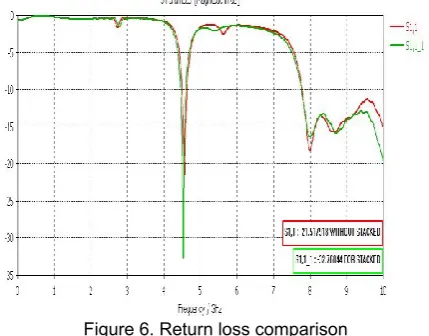
Figure ‘2’ shows the Return Loss (S11) of Edge Fed Micro strip Patch Antenna (EFMSPA) with twin slots at 4.56GHz is -21.5179.Figure 4 shows the Return Loss (S11) of Edge Fed Micro strip Stacked Patch Antenna (EFMSSPA) with twin slots at 4.53GHz is -32.7604.
Figure 4. Return loss (S11) of the edge fed microstrip
patch antenna with twin slots.
Figure 5. Return loss of the edge fed microstrip stacked patch antenna with twin slots.
The Comparisons of both EFMSPA and Edge Fed Micro strip Stacked Patch Antennawith twin slots are shown in Figure 6.
Figure 6. Return loss comparison
Available online:
http://edupediapublications.org/journals/index.php/IJR/
P a g e | 1256Figure 7. Standing wave ratio for EFMSPA with twin slots
Figure 8. Standing wave ratio EFMSSPA with twin slots
Comparisons of VSWR for both the results are shown in Figure 9.
Figure 9. Comparison of standing wave ratio
The Three Dimensional Radiation Pattern of Gain is shown in Figure 10 and the Gain obtained is high for Edge Fed Microstrip Stacked Patch Antenna (EFMSSPA) is 5.04db compared with EFMSPA with twin slots which is 3.28db.
Figure 10. Gain of EFMSPA with twin slots
Figure 11. Gain of EFMSSPA with twin slots.
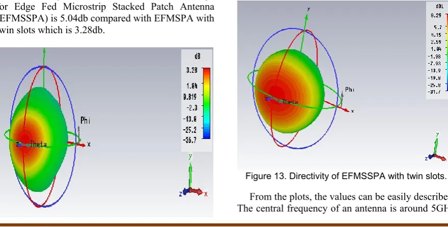
The Directivity of the EFMSPA and Edge Fed Microstrip Stacked Patch Antenna (EFMSSPA) with twin slots are 7.61dbi and 8.29dbi and are shown in Figure 12.
Figure 12. Directivity of EFMSPA with twin slots
Figure 13. Directivity of EFMSSPA with twin slots.
Available online:
http://edupediapublications.org/journals/index.php/IJR/
P a g e | 1257 which is lies in the C-band. The return loss of theEFMSPA is -21.5179dB and Edge Fed Microstrip Stacked Patch Antenna (EFMSSPA) with twin slots is -32.7604 which it can be stated that the Return Loss (S11) is improved. The VSWR is also improved by 1.1833 to 1.047. Maximum Gain 5.04db and is obtained by Stacked EFMSA. Directivity is also increased with 8.29dbi.
5. Comparative Analysis
The Performance Comparison of Return Loss (S11), VSWR, Gain and Directivity for EFMSPA and Edge Fed Microstrip Stacked Patch Antenna with twin slots are tabulated as follows in Table 2.
Table 2. Effect of stacked patch on s11, standing
wave ratio, gain and directivity
Parameters EFMSPA with twin slots
Edge Fed Microstrip Stacked Patch
Antenna with twin slots
Frequency 4.56GHz 4.53GHz
Impedance
Bandwidth (S11) -21.5179 -32.7604
VSWR 1.1833 1.047
Gain 3.28db 5.04db
Directivity 7.61dbi 8.29dbi
6. Conclusion
Here in this project the Stacked Edge Fed Microstrip Patch Antenna operating at C-band with 5GHz as central frequency has given the desirable features. Gain and directivity values of these antennas are 5.04db and 8.29dbi at 4.53GHz
frequency. The Return Loss (S11) of Edge Fed Micro strip Stacked Patch Antenna is -32.7604. From the above furnished data it can be easily depicted that edge fed microstrip stacked patch antenna is displaying appreciable values in all the parameters..
7. Acknowledgements
I would like to thank my college management for encouraging me in the fulfillment of this work and a special thanks to my faculty members who shared their helping hand all throughout this endeavor.
8. References
[1] Stutzman, Warren L., and Gary A. Thiele. Antenna
theory and design. John Wiley & Sons, 2012.
[2] James, James R., and Peter S. Hall, eds. Handbook of
microstrip antennas. Vol. 1. IET, 1989.
[3] Deshmukh, Amit A., A. A. Kadam, and K. P. Ray. "Analysis of slot cut broadband and dual-band rectangular
microstrip antennas." IETE Journal of Research 59.3
(2013): 193-200.
[4] Sainati, Robert A. CAD of microstrip antennas for
wireless applications. Artech House, Inc., 1996.
[5] Munson, Robert E., Hussain A. Haddad, and John W. Hanlen. "Microstrip reflectarray for satellite
communication and radar cross-section enhancement or reduction." U.S. Patent No. 4,684,952. 4 Aug. 1987.
[6]Ang, Boon-Khai, and Boon-Kuan Chung. "A wideband
E-shaped microstrip patch antenna for 5-6 GHz wireless
communications." Progress In Electromagnetics Research
75 (2007): 397-407.
[7]Pozar, David M. "Microstrip antennas." Proceedings of
the IEEE 80.1 (1992): 79-91.
[8] Alamouti, Siavash M. "A simple transmit diversity technique for wireless communications."
IEEE Journal on selected areas in communications
16.8 (1998): 1451-1458.
[9] Salonen, Pekka, Mikko Keskilammi, and Markku Kivikoski. "New slot configurations for dual‐band planar inverted‐F antenna." Microwave and Optical Technology Letters 28.5 (2001): 293-298.
[10] Balanis, Constantine A. Antenna theory: analysis and design. John Wiley & Sons, 2016. [11] Hirasawa, Kazuhiro, and Misao Haneishi, eds.