Quintuple-Mode Wideband Substrate Integrated Waveguide Filter
with Elliptic Dielectric Loading
Halima Ammari*, Mohamed L. Riabi, Farouk Grine, and Mohamed T. Benhabiles
Abstract—This paper presents a novel quintuple-mode wideband filter based on a circular Substrate
Integrated Waveguide (SIW) cavity. To implement this filter, a pair of two metallic perturbation
vias loaded around the diameter resonator line is used. An Elliptic Dielectric Resonator (EDR) was introduced in the middle of the cavity to shift certain resonant modes and restrain the higher-order modes. The optimal dimensions and dielectric permittivity of the EDR are investigated. A single SIW resonator filter has been designed, manufactured, and measured as an experimental example to verify the proposed design. Simulation and measurement results agree with 51.7% of fractional bandwidth at 10.1 GHz central frequency, with one transmission zero (TZ) at the lower frequency side and four TZs at the upper side.
1. INTRODUCTION
With the evolution of wireless communication systems and the advent of 5G, the wideband (WB) filters and ultra-wideband (UWB) filters are highly demanded in practice, due to their significant application in high rate communication systems and supporting multiple adjacent narrow bands transmission. Recently, the multiple-mode resonator (MMR) approach becomes an important key to reduce the
filter size and to improve the filtering performance, which was firstly proposed by [1]. Various
research studies on multi-mode filters based on different configurations have been done to extend the filtering bandwidth [2–9]. The multiple-mode stub-loaded resonators in [2, 3] exhibit good wideband performances with a very compact size. However, the transmission-line based resonators generally have a high conductor loss as well as low power-handling capability. Moreover, a new class of metal cavity wideband MMR filter was proposed in [4]. In this filter, the wideband MMR is achieved by using an off-centered perturbation approach instead of a traditional corner-cut configuration. Despite the simplicity of the filter structure, it does not provide enough fractional bandwidth. In [5], a quintuple-mode wideband filter was proposed. The implementation of this filter is based on three perturbation oriented metallic cylinders with two coupling probes in a single circular waveguide cavity. This proposed filter provided a fractional bandwidth of 36%. To improve the fractional bandwidth, the authors in [6] proposed a novel design of a quintuple mode filter based on a pair of metallic shorting pins, which were inserted into a rectangular cavity. This design has achieved a fractional bandwidth of 70%. Future telecommunication systems not only require high bandwidth but also consider a low cost design with high selectivity and compact size. All these requirements make Substrate Integrated Waveguide (SIW) an appropriate technology. For the implementation of multi-mode filters on SIW resonators, different designs have been proposed in [7–9]. A wideband SIW filter with compact size using U-shape slot on the metallic plate of an SIW cavity to produce five resonant modes was investigated in [7]. The proposed fifth-order passband filter was implemented on two SIW cavities and provided 42% fractional
Received 6 September 2019, Accepted 6 January 2020, Scheduled 21 January 2020
* Corresponding author: Halima Ammari (halima.ammari@umc.edu.dz).
bandwidth. In [8], a novel quintuple-mode was designed based on modified quarter mode substrate integrated waveguide (QMSIW). The filter can achieve only 22.5% fractional bandwidth. In [9], the authors suggested a very simple quintuple-mode filter design by introducing an elliptic metallic post
in the middle of an SIW rectangular cavity. The proposed filter provided five reflections and two
transmission zeros at the upper frequency side with fractional bandwidth up to 60%. However, this filter had a very narrow stopband rejection.
This paper proposes a novel SIW multi-mode cavity to design a compact wideband SIW filter with a selective response. To implement the proposed resonator, four metallic vias and an Elliptic Dielectric Resonator (EDR) are introduced in a circular SIW cavity to excite five resonant modes.
2. DESIGN AND SIMULATION
2.1. Cavity Structure and Electric Field Distribution in Eigen Modes
Figure 1 shows the layout of the proposed quintuple-mode resonator. The resonator consists of a
circular SIW cavity with a radiusR = 15 mm implemented on a Rogers 5880 substrate with a dielectric
permittivity r1 = 2.2 and thickness h = 0.787 mm. Two mechanisms of mode perturbation are
introduced in the cavity. Firstly, to excite the five resonant modes, a pair of two metallic vias is loaded around the cavity diameter line (AA) with (θ, t) = (20◦, 10.9 mm) as shown in Figure 1(a). The electric field patterns of the five degenerate modes are shown in Figure 2, which are a pair of perturbed
T M110 (named as T M1101 and T M1102 ), T M210, and a pair of perturbed T M020 (named as T M0201 and
T M2 020).
(a) (b)
Figure 1. The proposed quintuple-mode resonator design. (a) Geometry of circular SIW cavity loaded with metallic vias and EDR. (b) Configuration of the EDR.
(a) (b) (c) (d) (e)
Figure 2. Electric field distributions in circular SIW resonator loaded with four metallic vias for five distinct modes: (a)T M1101 , (b)T M1102 , (c)T M210, (d)T M0201 , (e) T M0202 .
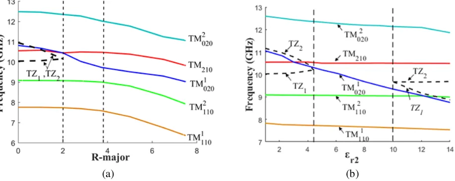
To define the EDR effect in the cavity, the variation of the five resonant frequencies versus the EDR geometry and permittivity is studied. The EDR dimensions are taken as Rminor = 0.6∗Rmajor.
Figure 3(a) represents the variation of the mode chart for the exciting modes on the function ofRmajor,
wherer2 = 6.15. Obviously, whenRmajor = 0 mm (the cavity perturbed only by the four metallic vias),
TZ supposes to appear between T M1102 and T M210, and another TZ separates T M0201 and T M0202 . The
increase of Rmajor enables to delete the TZs, which gives the possibility to implement the band-pass
filter. On the other hand, when Rmajor is less than 3.7 mm, the EDR influences only modes 4 and
5, because they reach their maximum in the center of the cavity. Meanwhile, modes 1, 2, and 3 have reached its minimum so remain unchanging. Furthermore, ifRmajortakes a greater value, the EDR effect
on all modes and the resonant frequencies decrease with the increase of Rmajor. Figure 3(b) shows the
effect of the EDR permittivity on the mode chart of the five resonant modes, where Rmajor= 2.8 mm.
It can be observed that whenr2 takes values between 4.5 and 10,T M0201 is sandwiched betweenT M1102
and T M210, and there are no TZs separate the five resonant modes.
(a) (b)
Figure 3. (a) Mode chart for the five resonant frequencies versus the size Rmajor. (b) Resonant
frequency variation of the five modes with the EDR permittivity.
In the proposed concept, the EDR is used to delete the undesirable TZs by shifting mode T M0201 betweenT M1102 and T M210. Following the EDR parametric optimization, the radius Rmajor should be
sandwiched between 2 mm and 4 mm, and the dielectric permittivity r2 takes values between 4.5 and
10.
The EDR substrate is chosen as Arlon ad 600 with a dielectric permittivity of r2 = 6.15 and
Rmajor = 3.15 mm. The new electric field distribution of the quintuple-mode cavity loaded is plotted in
Figure 4. As we provided earlier in the new field distribution, mode T M1
020 becomes the third mode
while mode T M210 becomes the fourth mode.
(a) (b) (c) (d) (e)
To verify our concept, the simulated transmission coefficients|S21|of the proposed quintuple-mode resonator with and without EDR are compared in Figure 5. Obviously, the use of the EDR allows the implementation of a quintuple mode filter with wide passband, as well as to improve the stopband rejection, and four TZs can appear at the right side when we use an appropriate EDR.
Figure 5. Simulated transmission coefficient of the proposed quintuple-mode resonator with and without EDR.
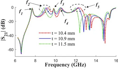
To estimate the factor of the four vias positions on the frequencies of the resonant modes, Figure 6 shows the simulated magnitude of |S21| with different t values. It is observed that the resonant frequencies f2, f4, and f5, which are representing by T M1102 , T M210, and T M0202 modes respectively,
decrease with the increase oft, whilef1andf3remain almost the same. This is because the perturbation
vias are located where the electric fields ofT M1101 and T M0201 are relatively weak. Thus, the operating bandwidth can be effectively adjustable and controllable.
Figure 6. Simulated transmission coefficient of the proposed quintuple-mode filter with variedt.
2.2. Quintuple-Mode SIW Filter
To demonstrate the performance of the proposed quintuple-mode cavity, a single cavity-filter based on this resonator is investigated. The basic structure of this filter is shown in Figure 7. To excite the five resonant modes a coplanar waveguide (CPW) transition with two slot lines is used. The CPW extends into the SIW resonator, and the two slot lines are divided toward the metallic perturbation vias to achieve a better energy transmission, considering that the energy is concentrated between the metallic perturbation vias (Figure 4).
Figure 7. Configuration of the proposed quintuple-mode SIW filter.
(a) (b)
Figure 8. (a) Topology of the quintuple-mode filter, (b)S-parameters of the proposed filter synthesized by matrix [M] and full-wave simulation.
lossy or lossless modes for better filter modeling [11]. Figure 8(a) depicts the coupling scheme of the proposed quintuple-mode SIW filter. In this diagram, modes 2, 3, 4, 5, and 6 generate the passband
response of the quintuple-mode filter. To provide the wideband filter, the higher and lower order
resonant modes must be taken into consideration. The first node corresponding to the fundamental mode isT M010. Modes 7, 8, and 9 are three higher orders lossy modes, corresponding to the frequencies
14.5, 15.2, and 16.1 GHz, respectively.
M
=
⎡ ⎢ ⎢ ⎢ ⎢ ⎣
0 0.3626 0.4050 −0.5289 0.5394 −0.4132 0.2151 −0.4413−0.015i −0.0381−0.0184i −0.2862−0.031i 0
0.3626 3.2609 0 0 0 0 0 0 0 0 0.3626
0.4050 0 1.1893 0 0 0 0 0 0 0 0.4050
−0.5289 0 0 0.6888 0 0 0 0 0 0 0.5289
0.5394 0 0 0 −0.1149 0 0 0 0 0 0.5394
−0.4132 0 0 0 0 −0.9010 0 0 0 0 0.4132
0.2151 0 0 0 0 0 −0.9267 0 0 0 0.2151
−0.4413−0.015i 0 0 0 0 0 0 −1.5309−0.015i 0 0 0.0423 + 0.0150i −0.0381−0.0184i 0 0 0 0 0 0 0 −1.6521−0.0184i 0 0.3324 + 0.0184i −0.2862−0.031i 0 0 0 0 0 0 0 0 −1.953−0.0310i 0.2862 + 0.031i
0 0.3626 0.4050 0.5289 0.5394 0.4132 0.2151 0.4413 + 0.015i 0.0381 + 0.0184i 0.2862 + 0.031i 0
⎤ ⎥ ⎥ ⎥ ⎥ ⎦
The external couplingMSi,MLi, and the diagonal elementsMiiare calculated by using the coupling matrix synthesis methods for Chebyshev filtering functions [12] using the software MATLAB code.
Figure 8(b) shows a comparison between the reflection coefficients (|S11|) and transmission coefficients (|S21|) of the full-wave simulation calculated using Ansoft HFSS and the results obtained from the coupling matrix [M]. As shown in this figure, the two simulations are in good agreement.
Figure 9. The configuration of the proposed filter with the air gap.
(a) (b)
Figure 10. (a) S-parameters of the proposed filter with varied g. (b) S-parameters of the proposed filter versusg and Rmajor.
metal plates of the cavity and between the EDR dielectric and the main dielectric of the SIW cavity. To eliminate the conductor air gaps effect, an adhesive copper tape is added after the integration of the EDR on the top and bottom layers. Meanwhile, to estimate the air gap impact between the EDR dielectric and principal SIW cavity dielectric, theS-parameters variations with various distances of air-gap representing by the factorgare plotted in Figure 10(a), whileRmajoris fixed at 3.3 mm. Obviously,
the first three modes change their frequencies with the increasing in g. That effect on the return loss is up to 12.3 dB when g = 1 mm. Therefore, to decrease the air gap impact it is sufficient to shift the resonant modes at their initial frequencies using the EDR. Figure 10(b) shows the appropriate EDR radius (Rmajor) for different air gap dimensions to keep the return loss less than 21 dB.
3. FABRICATION AND MEASUREMENT
To validate the design concept, a prototype filter has been fabricated. Photographs of the fabricated circuit are shown in Figure 11. The optimized parameters of the fabricated filter are as follows:
R1 = 15.6 mm, R2 = 16.5 mm, w1 = 2.6 mm, w2 = 4.2 mm, w3 = 1 mm, l1 = 4 mm, l2 = 3.4 mm,
p = 1 mm, (θ, t) = (17◦, 10.9 mm), g = 0.3 mm, Rmajor = 3.35 mm, and Rminor = 2.1 mm, ϕ = 10.5◦.
(a)
(b)
Figure 11. Photography of the fabricated quintuple-mode filter. (a) Top view, (b) bottom view.
Figure 12. S-parameters of the proposed filter.
The simulated return loss (RL) is greater than 21.4 dB, and the minimum insertion loss (IL) is 0.33 dB. On the other hand, the minimum measured insertion and return losses in the passband are 1.1 dB and 17.2 dB, respectively.
Table 1 demonstrates a comparison study of the performance of the present work with recently quintuple-mode filters. Through this comparison, the proposed quintuple-mode filter provides a high filtering performance, in terms of better return loss and high bandwidth (51.7%).
Table 1. Comparison with others reported quintuple-mode filters.
Filters Technology IL
(dB)
RL
(dB)
FC
(GHz)
FBW
(%)
Left
TZs
Right
TZs
[6] single metal cavity <0.65 10 5.8 70 1 3
[13] multiple-stub-loaded resonator <1.8 12.5 2.4 25.8 1 3
[7] SIW <1.1 12 10 48 0 0
[8] QMSIW <1.75 13.5 80 22 2 2
4. CONCLUSION
In this paper, a compact wideband passband filter on a single circular SIW resonator is investigated by using an elliptic dielectric resonator (EDR) loaded in the cavity center. Five resonant modes are produced in the desired passband. Transmission zero in the lower frequency side and four TZs in the upper frequency side are generated for better filtering selectivity and to improve the out-of-band rejection. The proposed design is fabricated with standard PCBs technology. It has been demonstrated with experimental results that the proposed filter shows an excellent performance in terms of bandwidth, losses, and compact size for wireless communication systems.
REFERENCES
1. Lin, W. G., “Microwave filters employing a single cavity excited in more than one mode,”J. Appl. Phys., Vol. 20, No. 8, 989–1001, 1951.
2. Zhang, Z.-C. and H. Liu, “A ultra compact wideband bandpass filter using a quadmode stub-loaded resonator,” Progress In Electromagnetics Research Letters, Vol. 77, 35–40, 2018.
3. Nan, L., Y. Wu, W. Wang, S. Li, and Y. Liu, “A compact wideband bandpass filter using a coupled-line quad-mode resonator,” Progress In Electromagnetics Research Letters, Vol. 53, 7–12, 2015.
4. Wong, S., S. Feng, L. Zhu, and Q. Chu, “Triple- and quadruple-mode wideband bandpass filter using simple perturbation in single metal cavity,” IEEE Transactions on Microwave Theory and Techniques, Vol. 63, No. 10, 3416–3424, 2015.
5. Wong, S., S. Feng, L. Deng, L. Zhu, and Q. Chu, “A quintuple-mode wideband bandpass filter on single metallic cavity with perturbation cylinders,”IEEE Microwave and Wireless Components Letters, Vol. 26, No. 12, 975–977, 2016.
6. Wong, S., B. Zheng, L. Zhu, and Q. Chu, “Quintuple-mode wideband filter based on a single metal cavity,” Electronics Letters, Vol. 53, No. 15, 1049–1050, 2017.
7. Chen, R. S., S. Wong, L. Zhu, and Q. Chu, “Wideband bandpass filter using U-slotted substrate integrated waveguide (SIW) cavities,” IEEE Microwave and Wireless Components Letters, Vol. 25, No. 1, 1–3, 2015.
8. Huang, X., L. Zhou, Y. Yuan, L. Qiu, and J. Mao, “Quintuple-mode W-band packaged filter based on a modified quarter-mode substrate-integrated waveguide cavity,” IEEE Transactions on Components, Packaging and Manufacturing Technology, Vol. 9, No. 11, 2237–2247, 2019.
9. Ammari, H., M. L. Riabi, F. Grine, M. T. Benhabiles, R. Khalef, and C. Erredir, “Novel quintuple-mode wideband filter based on substrate integrated waveguide using an elliptic metallic post,”
International Symposium on Antennas and Propagation (ISAP), 1–2, Busan, Korea (South), 2018. 10. Amari, S., “Application of representation theory to dual-mode microwave bandpass filters,” IEEE
Transactions on Microwave Theory and Techniques, Vol. 57, No. 2, 430–441, 2009.
11. Das, R., Q. Zhang, A. Kandwal, and H. Liu, “All passive realization of lossy coupling matrices using resistive decomposition technique,” IEEE Access, Vol. 7, 5095–5105, 2019.
12. Hong, J., Microstrip Filters for RF/Microwave Applications, Wiley, New York, 2011.

![Figure 8(b) shows a comparison between the reflection coefficients (|coefficients (from the coupling matrix [S11|) and transmission|S21|) of the full-wave simulation calculated using Ansoft HFSS and the results obtainedM]](https://thumb-us.123doks.com/thumbv2/123dok_us/1964597.1259076/5.612.236.380.82.226/comparison-reection-coecients-coecients-transmission-simulation-calculated-obtainedm.webp)


