Application of an Improved GSC in TTE Communication
with Antenna Array
Ning Zhang1, Yu Zhong Jiang1, *, and Ming Ming Li2
Abstract—By analyzing the characteristics of the super low frequency (SLF) electromagnetic wave in through the earth (TTE) communication, an orthogonal array of magnetic antenna is proposed for receiving SLF signal, and a new robust adaptive beamformer is used to process the received signals. The proposed beamformer is a multi-input generalized sidelobe canceller (GSC) with a coefficient constrained adaptive blocking matrix and a filter based on minimum mean-square error (MMSE) criterion. It can reduce the leakage of the desired signal and enhance the capability of interference cancellation. The received signals of the main antennas and the reference antennas of the antenna array are input to the beamformer as desired signal and reference signal, respectively. Both simulated and experimental results show that the proposed beamformer can suppress the single-tone and phase modulation interference, whose frequency is close to the desired signal’s frequency. The proposed beamformer has better effect and robustness on interference cancellation than the traditional GSC.
1. INTRODUCTION
TTE communication plays a very important role in coal mine safety production scheduling and emergency rescue. When the electromagnetic wave penetrates the rock layer (conductive medium), the higher the frequency of electromagnetic wave is, the stronger the power attenuation will be. Therefore, mine wireless communication usually uses SLF electromagnetic wave on the deep communication of the mine. Its skin depth can be tens of kilometers in granite strata, which provides a possibility for the TTE communication. However, the biggest problem of SLF communication is that the interference in the band is very complex. Besides, the transceiver antenna is difficult to reach the magnitude of its wavelength, and the efficiency of the antenna is low, which causes the limited power of desired signal. Therefore, a group of high-performance antennas are required at the receiver. The parasitic smart antennas and high sensitivity magnetic antennas proposed by [1] and [2] respectively are helpful for improving the performance. At the same time, an effective method of canceling interference noise is needed to improve the performance of TTE communication.
In the TTE communication, man-made noise is generally dominated by the 50 Hz power frequency harmonic interference [3] generated by underground power line, as well as the radio frequency (RF) interference produced by electrical equipment and communication users. These interferences will reduce the signal-to-noise ratio (SNR) of the desired signal and increase the difficulty of signal processing after the antenna receives them. Various forms of frequency-domain filters can be used to suppress the fixed frequency interference outside the work band [4–6]. However, in practice, some interference will be in the work band, which must be processed with other methods. Traditional interference cancellation algorithms usually use only single channel, whose available information is limited. By comparison, multichannel methods are especially promising systems in terms of interference cancellation. For
Received 27 May 2018, Accepted 12 July 2018, Scheduled 24 July 2018 * Corresponding author: Yu Zhong Jiang ([email protected]).
1 College of Electronic Engineering, Naval University of Engineering, Wuhan, Hubei 430033, China. 2No. 91878 Troops, Zhanjiang,
example, reconfigurable planar array antenna and GSC, which are based on adaptive beamforming, have been widely used in the Wi-Fi application and microphone array signal processing, respectively [7, 8]. However, because the microphone spacing is generally greater than the voice signal wavelength, with the classic adaptive beamformer based on GSC, like the Griffiths-Jim beamformer [9] and some others, slight direction estimation error will cancel part of the desired signal [10]. Many signal processing techniques, which are called robust adaptive beamforming, have been proposed to avoid the cancellation of the desired signal [11–15], because their performance is robust against errors. However, the problems of using GSC algorithm are not so serious while processing SLF signals. Because the spacing of the array is far less than the SLF electromagnetic wavelength (1–10 million meters), shifting only a few sampling points can compensate the delay. This is beneficial to the use of antenna array method in the TTE communication [16].
Therefore, according to the characteristics of GSC algorithm, the method of using orthogonal antenna array in TTE communication is proposed for the first time. Given that all the units have equal spacing and same main lobe orientation in traditional antenna array, the sidelobe interference is difficult to be cancelled. However, in the proposed method, the main antenna and reference antenna arranged orthogonally will be beneficial for receiving the interference from all directions of space. Besides, extending the traditional speech signal processing method to TTE communication can effectively reduce the bad effects caused by estimation errors of steering vectors. To overcome the difficulties of the original algorithm, a new robust adaptive beamformer based on the classical GSC algorithm is proposed. The basic idea of the interference cancellation scheme is to use the reference antenna to enhance the signal of the upper branch and by optimizing the blocking matrix to reduce the leakage of desired signal. The recursive least square method (RLS) is also used for the multi-channel adaptive interference cancellation (MC). In Section 2, the receiving antenna and receiving signal are modeled, and the basic principle of the improved GSC algorithm is introduced. Section 3 tests the interference cancellation scheme. Section 4 summarizes the content of this paper.
2. METHODS
2.1. Antenna Array and Signal Models
Figure 1 shows a schematic diagram of a typical mine wireless TTE communication system [16]. The system uses a large ring antenna (2 to 10 kilometers in length) to transmit the magnetic signals that carry information, and the downhole person uses a small ring antenna mounted on the helmet to receive it. It is difficult to detect and extract the desired signal only by using single antenna because the high conductivity of the mineral soil will cause serious power attenuation of the electromagnetic wave. There are many kinds of electromagnetic interference in the working environment. To overcome the problem,
Earth's crust Earth's surface
Mine
Transmitting antenna
Receiving antenna
Figure 1. Schematic diagram of a typical mine wireless TTE communication system.
X-axis
Y-axis
p1 p2
n2
n1 Desired Signal
Interference
Z-axis
this paper proposes an antenna array whose layout structure is shown in Fig. 2. The main antennas p1, p2 and reference antennas n1, n2 are placed orthogonally. Since the direction of the magnetic core has the maximum gain, that orthogonal to it has the minimum gain, when the cores of the main antennas p1 and p2 aim at the direction of the desired signal, the reference antennas will receive the least desired signal. At the same time, the reference antennas can also receive the projection component of the interference from the space. Theoretically, the two reference antennas arranged orthogonally in the method as shown in Fig. 2 can receive any interference from any direction, except the direction where desired signal comes. In addition, when a specific algorithm is used to deal with the data received by two main antennas, part of the interference from the direction of the main antenna can be extracted, and combining it with the reference antennas signals will greatly enrich the interference information.
According to the antenna array model proposed in the previous section, the signal received by a certain main antenna at a certain time can be expressed as:
xp(n) =s(n) + K
j=1
PX(ϕwj, θwj)wj(n) + L
k=1
PX(ϕrk, θrk)rk(n) +nα(n) +ni(n) (1)
where,
PX(ϕwj, θwj) = cosϕwj
PX(ϕrk, θrk) = cosϕrk
(2)
(ϕ, θ) is the angular relation between interference signal and desired signal, and PX(·) is the projection operator, which represents a signal projected to the X axis. s(n) is the desired signal, wj(n) the jth power-line interference, rk(n) the kth RF interference signal, nα(n) the atmospheric noise, and ni(n) the background noise which can be considered as white noise.
Since the reference antenna’s structure is the same as the main antenna and its received signal almost does not contain the desired signal, the signal received by a reference antenna on the Y axis at a certain time can be approximately expressed as:
ˆ
xref(n−τ) = K
j=1
PY(ϕwj, θwj)wj(n) + L
k=1
PX(ϕrk, θrk)rk(n−τ) +nα(n−τ) +nα(n−τ) (3)
whereτ is the delay of the signal reaching reference antenna after main antenna. However, because the wavelength of SLF electromagnetic wave is far greater than the spacing between magnetic antennas,τ can be neglected approximately. So
ˆ
xref(n−τ) = ˆxref(n) (4)
In addition, because the reference antenna is orthogonal to the main antenna, the power of interference projected on the reference antenna is different from that of the main antenna. At the same time, the gains of different antennas and different amplification circuits are also needed to be taken into account, so the superscript in ˆxref(n) in formula (3) shows that it can be approximated by multiplying a random factor.
2.2. Traditional GSC Algorithm
The generalized sidelobe canceller (GSC) is an unconstrained time domain adaptive beamforming method proposed in 1982 [9]. In principle, it is an adaptive beamformer consisting of two parts of the main channel and auxiliary channel. By utilizing a blocking matrix, the constraint conditions in the traditional adaptive beamforming algorithm are separated from the system. The block diagram of the algorithm is shown in Fig. 3.
BM
+-FBF
MC
Z 1 a 2 a a..
.
..
.
..
.
..
.
x 1(n)
x (n)
x (n)
2
M
M - 1
y(n)
y f (n)
-L
y (n)
y (n)
y (n)
b, 1
b, 2
b, M - 1
y s(n)
Figure 3. Structure of the generalized sidelobe canceller.
which adaptively cancel the interference correlated to the output signal of BM from the delayed output signal of FBF. In the microphone array signal processing, because the wavelength of the speech signal is close to the spacing of the microphone array, the error of the microphone arrangement and the steering vector error of the target are easy to cause the leakage of the desired signal. However, because the spacing of the array is far less than the SLF electromagnetic wavelength, and the power attenuation of SLF electromagnetic wave in free space is about 1 dB per million meters, BM is not very sensitive to the steering vector error in TTE communication. Therefore, the GSC algorithm can be more easily implemented in the TTE communication than in the microphone array. However, it is still found in practice that the delay between different antennas’ signals cannot be ignored, and the gains of different channels are different. The traditional GSC algorithm performs poorly in practical applications. Therefore, this paper proposes an improved GSC algorithm for TTE communication which is robust.
2.3. Proposed Improved GSC Algorithm
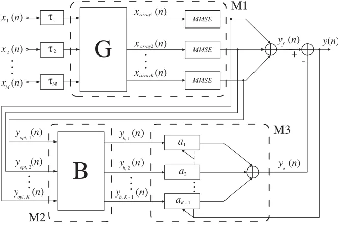
The structure of the proposed algorithm, called M-GSC, is shown in Fig. 4. The traditional GSC algorithm only uses the signal of the main antenna, but the improved algorithm will use an extra signal
+
-M1
M2
M3
MMSE MMSE MMSEG
B
1 a 2 a a..
.
..
.
x 1(n)
x (n)
x (n)
2
M
K - 1
y(n)
y f (n)
y (n)
y (n)
y (n)
b, 1
b, 2
b, K - 1
y s(n)
y (n)
y (n)
y (n)
opt, 1
opt, 2
opt, K
..
.
..
.
..
.
x array1(n)
x (n)
x (n)
array2 arrayK τ τ τ 1 2 M
from reference antenna. The principle of the proposed algorithm is to enhance the signal by using the MMSE method in the upper path and to minimize the leakage of the desired signal in the BM output signal by using the adaptive coefficient adjustment method. The algorithm consists of three modules, M1, M2, and M3.
2.3.1. M1: Signal Enhancement Based on MMSE Criterion
The function of the module M1 is to group the input antenna array signals and input them to the next level of the filter based on the MMSE criterion to get the enhanced signal. Suppose that M is the number of input signals, K the number of main antenna signals, and M −K the number of reference antenna signals. These signals are respectively expressed as
Xp(n) = [x1(n), x2(n), . . . , xK(n)]
Xr(n) = [xK+1(n), xK+2(n), . . . , xM(n)]
(5)
The array signal is input to matrixGafter delay compensation, and the output result is described as
XArray(n) =GT
D1 O
O D2
(6)
where
GT = [E|C]
D1= [x1(n), x2(n), . . . , xK(n)]
D2= diag[xK+1(n), xK+2(n), . . . , xM(n)]
(7)
GT is the packet matrix,E theK order unit matrix, andCa matrix ofK×(M−K) dimensions with all the elements being 1.
In fact, the function of signal grouping is to form a column vector with one of the main signals and all the reference signals as the input of one filter. The filter is designed based on the MMSE criterion, and the filter coefficient can be solved by using the desired signal and interference signal in theory. However, this is difficult to achieve in practice. For this reason, the main and reference signals are used as the estimation of the desired signal and interference, respectively. According to the MMSE criterion, the optimal weight coefficient of a filter is described as
Wopt,i(n) = ˆRr−1(n)E[XTr(n)xi(n)], (i=K, K+ 1, . . . , M) (8)
ˆ
Rr(n) is the estimation of the covariance matrix of the reference signal, andE[ ] represents mathematical expectations. Both the solution of expectation and the estimation of covariance matrix require a certain length of sampling data. Therefore, in the process of signal processing, we usually add window to the collected data. If the width of a window is N, the input array signal after windowed is an M ×N dimensional matrix. The main and reference signals are respectively expressed as
Xp = [x1,x2, . . . ,xK]T
Xr = [xK+1,xK+2, . . . ,xM]T
(9)
Therefore, Formula (8) is modified to
Wopt,i= ˆR−r1E[XTrxi], (i=K, K+ 1, . . . , M) (10)
where
ˆ
R−r1 = 1 N
N
i=1
Xr(i)[Xr(i)]H (11) Therefore, the output of the filter is
yopt,i(n) =xi(n)−WTopt,iXr(n) (12)
Finally, the output signal after enhanced is
yf(n) = M
i=1
2.3.2. M2: Signal Processing in Adaptive Coefficient BM
According to the previous analysis, the delay of each channel is easy to compensate. When blocking, only adjusting the coefficient can cancel the desired signal well. Therefore, this paper proposes an improved BM which is easy to implement. Set the initial matrix
B=
⎡ ⎢ ⎢ ⎢ ⎣
1 −1 0 . . . 0
0 1 −1 . .. 0 ..
. . .. ... ... ...
0 . . . 0 1 −1
⎤ ⎥ ⎥ ⎥
⎦ (14)
where Bis a (K−1)×M dimensional matrix, whose function is to subtract any two adjacent signals in the time domain to cancel the desired signal. However, the signal of each main antennas is different, even if the signals have been compensated accurately, only using Formula (14) cannot completely block the desired signal. Therefore, an adaptive coefficient BM is proposed, and it is described as
BM =
⎡ ⎢ ⎢ ⎢ ⎣
1 α1 0 . . . 0
0 1 α2 . .. 0 ..
. . .. ... ... ...
0 . . . 0 1 αK−1
⎤ ⎥ ⎥ ⎥
⎦ (15)
Supposing thatbirepresents theith row of the BM, the problem of solvingαis described as follows:
min SINRF(biYopt, f)
s.t. ξd< αi< ξt (16)
where
Yopt= [yopt,1,yopt,2, . . . ,yopt,K]T
SINRF(x, f) = 10 lg Ps Pn
(17)
Yopt is the input vector of the lower path, SINRF(x, f) the SINR of signalxat frequencyf,Ps the power of desired signal, andPnthe power of interference and noise power, which is the average power in bandwidthB around frequencyf. ξd andξt are used to limit the range of α. Because the performance parameters of the antenna are similar, the adjustment range of α is tiny. Therefore, controlling the scope of α is conducive to obtaining the optimal solution faster.
2.3.3. M3: Signal Processing in MC
The BM output signal is sent to module M3 as a reference signal for adaptive processing together with the upper path output. To improve the performance of the MC, this paper uses RLS to replace Least Mean Square (LMS) algorithm, which has the advantages of faster convergence speed and stronger filtering ability. The derivation of the algorithm is complicated, so the iterative formula for solving RLS problem is given directly [17]:
yi(n) =yf(n)−aTi (n)yb,i(n)
K(n) = P(n−1)yb,i(n) λ+yTb,i(n)P(n−1)yb,i(n) P(n) = 1
λ[P(n−1)−yTb,i(n)∗K(n)P(n−1)]
aTi (n) =aTi (n−1) +K(n)yi(n)
(18)
In the formula, λ is called forgetting factor, which is equivalent to the step length. K(n) is the gain vector, and the correction ability of the algorithm will increase with the increase of K(n). P(n) can prevent the system mutation and enhance the stability of the system. aT
i (n) and yi(n) are the
3. EXPERIMENTAL RESULTS AND DISCUSSIONS 3.1. Simulation Results
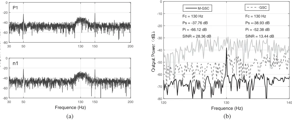
According to the model shown in Fig. 2, simulation experiments are carried out to verify the effectiveness of the improved algorithm. It is assumed that the desired signal is a single-tone signal of 130 Hz. The power frequency interferences are 50 Hz and 150 Hz. The radio frequency interference is an MSK signal of the carrier 132 Hz, and its spectrum can completely submerge the desired signal. The atmospheric noise and background are set to Gauss white noise. It is assumed that ϕ and θ of all the interference signals are 45◦. Because any two antennas of the array are different, an interference projection factor is multiplied for each antenna, which is randomly generated within the range of 0.9 to 1.1. The sampling frequency is 1000 Hz, and the received signals of each antenna are delayed 2, 4 and 6 sampling points, respectively. Fig. 5(a) shows the power spectra of the signal received by the main antenna p1 and the reference antenna n1 respectively.
30 50 130 150 200
-80 -60 -40 -20 0
P1
30 50 130 150 200
Frequence (Hz)
-80 -60 -40 -20 0
n1
120 130 140
Frequence (Hz)
-80 -70 -60 -50 -40 -30 -20 -10 0
Fc = 130 Hz Ps =-38.93 dB Pi = -52.38 dB SINR = 13.44 dB Fc = 130 Hz
Ps = -37.76 dB Pi = -66.12 dB SINR = 28.36 dB
GSC M-GSC
(a) (b)
Figure 5. Comparison of the performance of two algorithms.
In Fig. 5(b), the grey solid line represents the original signal of the main antenna. The desired signal is completely submerged by interference, and the SINR is negative. When the signal is processed, the situation is improved. It can be seen from the graph that the M-GSC algorithm’s performance represented by the black solid line is better than the traditional GSC algorithm represented by the dashed line. The M-GSC algorithm fully cancels the MSK signal, restoring the desired signal and reducing the average noise power in the band more effectively. Compared to the processing results of the GSC algorithm, the SINR is improved by 14.92 dB.
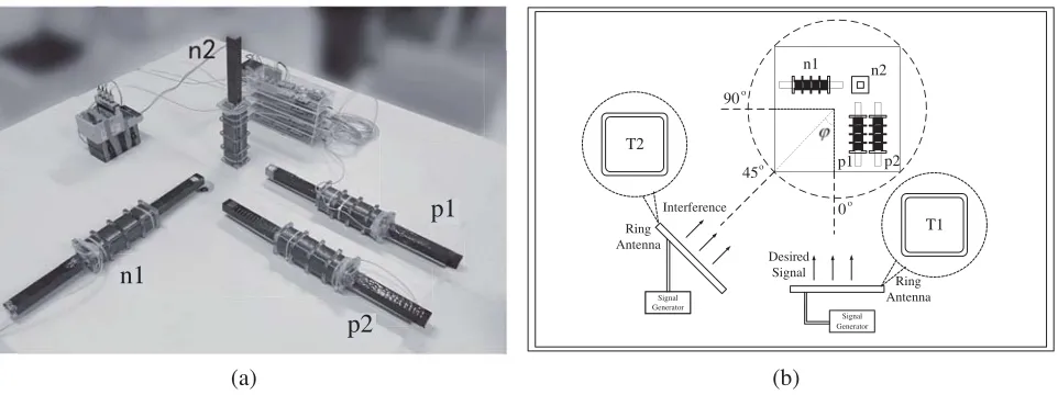
3.2. Set Up Experiment
In the working environment, the interference of the SLF band is complex. Therefore, the algorithm needs to be verified in real environment. According to the proposed antenna model, four self-made magnetic antennas, as shown in Fig. 6(a), are used to build the array model, and the ring antenna, as shown in Fig. 6(b), is used to radiate the desired signal and interference signal. The experimental scene is arranged according to Fig. 6(b). The ring antennas T1 and T2 are placed at the same distance from the antenna array’s center and the same height from the ground. The angle difference between the two signals radiated by T1 and T2 is ϕ. When the ring antenna T1 radiates the desired signal from p1 and p2, the steering vector of the interference is (ϕ,0).
!
Signal Generator Signal
Generator
p1 p2
n1 n2
Ring Antenna
Desired Signal
T1 T2
Ring Antenna Interference
(a) (b)
n1
p2
p1 0
45 90
o o
o
Figure 6. Experimental equipment and scene.
wide comparison with other techniques, this paper adds multi-channel LMS and RLS algorithms as comparison groups [17, 18].
3.3. Result Analysis
In Table 1, the interference cancellation performance of the two algorithms under experiment in different interference environments is summarized. The four algorithms are all effective for different types of interference, but the performance of the M-GSC algorithm proposed in this paper is better than that of other methods. Therefore, the improvement of GSC algorithm by M-GSC algorithm is mainly discussed.
Table 1. Comparing the performance of M-GSC algorithm with traditional GSC\LMS\RLS algorithm.
Real environment Interference type
Interference
steering vector Input SINR improvement (dB) (ϕ, θ) SINR (dB) LMS RLS GSC M-GSC
Single-tone signal
(30◦, 0◦) 3.84 4.28 10.2 6.94 25.1
(45◦, 0◦) 2.66 4.99 6.15 5.7 22.7
(60◦, 0◦) 2.18 3.63 4.68 7.93 19.42
Phase modulation interference
(30◦, 0◦) −1.53 4.95 9.62 3.12 21.22 (45◦, 0◦) −2.68 1.61 5.09 0.24 19.23 (60◦, 0◦) −2.99 2.77 4.27 4.08 14.85
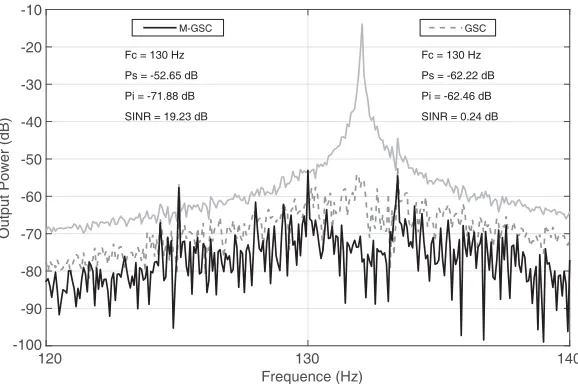
With the decrease of ϕ, the performance of traditional GSC algorithm has not changed regularly. However, the performance of M-GSC algorithm decreases with the increase ofϕ, which is in line with the actual situation. Because with the increase ofϕ, the interference signal in reference signal will decrease, which causes the upper path output to become weaker. However, it can still cancel interference, which shows that the proposed algorithm is robust.
120 130 140 Frequence (Hz)
-100 -90 -80 -70 -60 -50 -40 -30 -20 -10
Fc = 130 Hz
Ps = -62.22 dB
Pi = -62.46 dB
SINR = 0.24 dB Fc = 130 Hz
Ps = -52.65 dB
Pi = -71.88 dB
SINR = 19.23 dB
GSC M-GSC
Output Power (dB)
Figure 7. Comparison of the performance of two algorithms in the real environment (ϕ= 45◦).
4. CONCLUSIONS
In this paper, the problem of using SLF electromagnetic wave in TTE communication has been analyzed. Using antenna array and improved GSC algorithm in TTE communication has been proposed and verified in both the simulation and real environment. The proposed algorithm is a GSC equipped with an adaptive coefficients BM and a beamformer based on MMSE criterion. Experiments in real environment have shown that the proposed improved GSC algorithm can suppress the single-tone and wide-band interference from a certain angle range of incidence. It not only improves the traditional GSC algorithm, but also has strong robustness.
REFERENCES
1. Viani, F., L. Lizzi, M. Donelli, D. Pregnolato, G. Oliveri, and A. Massa, “Exploitation of parasitic smart antennas in wireless sensor networks,”Journal of Electromagnetic Waves and Applications, Vol. 24, No. 7, 993–1003, 2010.
2. Chen, L., P. Li, Y. Wen, and D. Wang, “High sensitivity magnetic sensor consisting of ferromagnetic alloy, piezoelectric ceramic and high-permeability FeCuNbSiB,” Journal of Alloys & Compounds, Vol. 509, No. 14, 4811–4815, 2011.
3. Yan, L., J. Waynert, C. Sunderman, and N. Damiano, “Statistical analysis and modeling of VLF/ELF noise in coal mines for through-the-earth wireless communications,” Industry Applications Society Meeting, 1–5, 2014.
4. Tokan, F. and F. Gunes, “The multi-objective optimization of non-uniform linear phased arrays using the genetic algorithm,” Progress In Electromagnetics Research B, Vol. 17, 135–151, 2009. 5. Lin, W.-J., C.-S. Chang, J.-Y. Li, D.-B. Lin, L.-S. Chen, and M.-P. Houng, “Improved compact
broadband bandpass filter using branch stubs co-via structure with wide stopband characteristic,” Progress In Electromagnetics Research C, Vol. 5, 45–55, 2008.
6. Sameni, R., “A linear Kalman notch filter for power-line interference cancellation,” Csi International Symposium on Artificial Intelligence and Signal Processing, 604–610, 2012.
7. Donelli, M. and P. Febvre, “An inexpensive reconfigurable planar array for Wi-Fi applications,” Progress In Electromagnetics Research C, Vol. 28, 71–81, 2012.
9. Griffiths, L., J. Jim, and W. Charles, “An alternative approach to linear constrained adaptive beamforming,” IEEE Trans. Antennas& Propag., Vol. 30, No. 1, 27–34, 1982.
10. Hoshuyama, O., A. Sugiyama, and A. Hirano, “A robust adaptive beamformer for microphone arrays with a blocking matrix using constrained adaptive filters,” IEEE Transactions on Signal Processing, Vol. 47, No. 10, 2677–2684, 1999.
11. Gu, Y., N. A. Goodman, S. Hong, and Y. Li, “Robust adaptive beamforming based on interference covariance matrix sparse reconstruction,” Signal Processing, Vol. 96, No. 5, 375–381, 2014.
12. Huang, L., J. Zhang, X. Xu, and Z. Ye, “Robust adaptive beamforming with a novel interference-plus-noise covariance matrix reconstruction method,” IEEE Transactions on Signal Processing, Vol. 63, No. 7, 1643-1650, 2015.
13. Somasundaram, S. D., N. H. Parsons, P. Li, and R. C. D. Lamare, “Reduced-dimension robust capon beamforming using Krylov-subspace techniques,” IEEE Transactions on Aerospace Electronic Systems, Vol. 51, No. 1, 270–289, 2015.
14. Gu, Y. and A. Leshem, “Robust adaptive beamforming based on interference covariance matrix reconstruction and steering vector estimatio,” IEEE Transactions on Signal Processing, Vol. 60, No. 7, 3881–3885, 2012.
15. Zhang, Z., W. Liu, W. Leng, A. Wang, and H. Shi, “Interference-plus-noise covariance matrix reconstruction via spatial power spectrum sampling for robust adaptive beamforming,” IEEE Transactions on Signal Processing, Vol. 23, No. 1, 121–125, 2015.
16. Yarkan, S., S. Guzelgoz, H. Arslan, and R. R. Murphy, “Underground mine communications: A survey,” IEEE Communications Surveys& Tutorials, Vol. 11, No. 3, 125–142, 2009.
17. Mahinthan, V., B. Kannan, and A. Nallanathan, “Performance of LSE-RLS-based interference cancellation scheme for STBC multiuser systems,”Electronics Letters, Vol. 38, No. 25, 1729–1730, 2003.
![Figure 1 shows a schematic diagram of a typical mine wireless TTE communication system [16]](https://thumb-us.123doks.com/thumbv2/123dok_us/1974099.1260608/2.612.322.548.535.694/figure-shows-schematic-diagram-typical-wireless-tte-communication.webp)