A Novel Area-Efficient T-Decoders For Recursion Computation
1M . Ranjith Kumar , 2S k. Mohiddin, 3S. Vijay1Assistant Professor, Amritha sai institute of science and technology, paritala, Krishna dt, A.P 2Assistant Professor, Sri Sarathi Institute of Engineering and Technology, Nuzvid, Krishna dt, A.P
3
VLSI Project Trainer, Elite Technology, Guntur, A.P
ABSTRACT: Long Term Evaluation (LTE) has been used to achieve peak data rates in wireless communication system. Turbo codes are utilized as the channel encoding scheme. MAP algorithm has been used as a decoding scheme. Complexity in MAP algorithm is minimized by implementing the algorithm in log domain giving rise to Log MAP algorithm. The main purpose is for reducing the difficulty of state metric computation by employing of numerous algorithms and these algorithms differ only by their implementation of correction terms. By utilizing constant log MAP algorithm, linear log MAP algorithm, MAX log MAP algorithm, multi step log MAP algorithm and hybrid log MAP algorithm ACS unit is implemented. The state metric calculation is implemented with the help of radix-4 Add -Compare-Select (ACS) unit. The distance calculation is involved between two concurrent computations of state metric can be shared among them which give rise to Maximum Shared Resource (MSR) architecture. The proposed implementation of these algorithms leads to reduction in the power dissipation, propagation delay and the number of logical elements used for the recursion computation in turbo decoders used in LTE system.
Keywords: Add–Compare–Select (ACS) Unit; Long-Term Evolution (LTE); Turbo Decoder; Wireless Communications).
I. INTRODUCTION
Many advanced wireless communication standards adopted turbo codes as the channel coding scheme because of its near Shannon error-correcting performance.
The procedure of decoding is performed in two different half iterations. One is even half iteration and another one is odd half iteration.
Now a days, long-term evolution (LTE) advanced has been dominated as the next-generation wireless
communication standard, which is aimed at higher peak data rates close to 3 Gb/s. The turbo decoder is specific in LTE. It reveals to be a limiting block toward this objective because of its iterative decoding nature, high latency, and significant silicon area consumption. The decoding procedure is operated by utilizing the algorithm. Since the providing of the actual maximum a posteriori (MAP) algorithm incurs very high computational complexity, typically, two modified forms of the MAP algorithm.
Log-likelihood ratio (LLR) units and the core units are included in the MAP core for computing the forward (α), backward (β), and branch metrics (γ) respectively. The γ unit, is a trivial part of the turbo decoder which consists of few addition computations. Therefore, an area-efficient architecture for α and β metrics computation is highly desirable, which has always been a challenge in literature.
In order to address this challenge, in this brief, a new relation between the α and β metrics is introduced based on this new relation, a novel add–compare– select (ACS) unit for forward and backward computation is proposed. The proposed scheme results in, at most, an 18.1% reduction in the silicon area compared with the designs reported to date.
II. TURBO DECODER ALGORITHM
where the probabilities of bit uk are denoted as p(uk
= +1| y) and p(uk = −1|y) as being +1 and −1,
respectively.
Two recursive conventional encoders are there in turbo decoders. The conventional encoder generates parity denoted as xkp1. The second covolutional
encoder also generates the second sequence of parity denoted as xkp2. This computation is done by
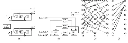
exchanging the extrinsic LLRs among two SISO decoders depend on equation (1). Trellis diagram is shown in Fig. 1(c) which is other representation of a conventional encoder.
Fig. 1. (a) Turbo encoder. (b) Turbo decoder. (c) Radix-2 trellis diagram. (d) Partial radix-4 trellis diagram.
The second equation is the manipulation of (1)
where forward, backward and branch metrics are denoted as ˜αk(s), ˜ βk(s), and ˜γk(s|,s) respectively.
The s and s| indexes are also associated with trellis
steps k and k − 1, respectively.
The MAP algorithm travels in both forward and backward directions to obtain state metrics ˜αk(s) and ˜ βk(s), respectively. The transmission value in the kth stage from the state s| to the state s is
denoted by ˜γk(s| , s). The calculations of the ˜αk(s), ˜ βk(s), and ˜γk(s| , s) metrics are performed as
where Xsk and Xpk are the received soft inputs corresponding to transmitted bits xs k and xp k, respectively. The value of Le(uk) denotes the extrinsic value of uk, and Lc is the channel reliability measure. uk and ck are the transmitted values of the systematic and parity bits, respectively, which can be either +1or −1.
Due to the high computational complexity of the MAP algorithm, which is as a result of the exponential and multiplication calculations, typically, an equivalent logarithmic form is employed, where a multiplication is converted to an addition. In this case, the corresponding equations in (2)–(5) can be reformulated as
where α, β, and γ_ are defined as
two common approaches are normally used, namely, the max-MAP and precise approximation of log-MAP algorithms.
Consider the following equation used to implement the logarithm:
where the max function denotes the maximum value. In the precise approximation of log-MAP method, the first term in (12), i.e., max(z, t), can be easily implemented by a comparator, whereas the second term, i.e., log(1 + e−|z−t|), which is produced by utilizing a lookup table (LUT). On the other hand, the max-log-MAP method relies on the approximation of log (ez + et) by the maximum of z and t, i.e., max *(z, t) ≈ max (z, t).
In order to improve the processing speed of the decoding algorithm, a radix-4 architecture is generally used by incorporating two stages of the trellis diagram, as partially shown in Fig. 1(d). In this case, two LLR values are produced simultaneously per clock cycle, increasing the throughput by a factor of 2. The transmission metrics are as fallows
where s” denotes the (k − 2)th stage of the trellis diagram.
III. ACS ARCHITECTURE
Fig. 2. (a) Conventional radix-2 ACS unit. (b) Conventional radix-4 ACS unit.
shown in Fig. 2(a), where common approximations of the logarithmic term in log(1 +e−|z−t|) are used for implementing the LUT. However, in recent wireless communication systems with a clear demand for a high-throughput framework, a radix-4 architecture is a common approach and should be efficiently designed.
However, compared with its radix-2 counterpart, it has a higher latency and silicon area overhead. Therefore, due to the nature of the recursive computation, which highly restricts the clock frequency, achieving a high throughput is by far a more challenging task in a radix-4 framework.
IV. PROPOSED SCHEME
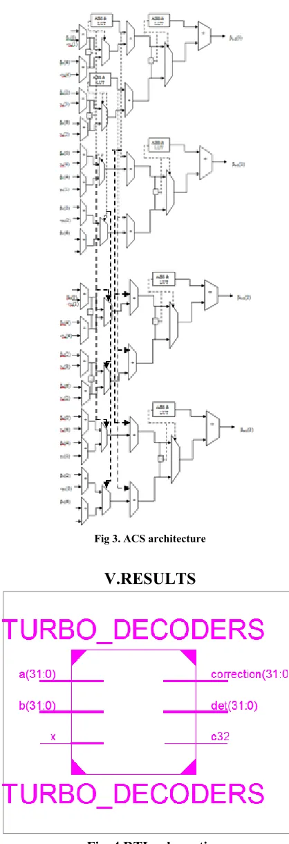
The proposed scheme is shown in Fig. 3.The value of βk−2(1) can be also similarly implemented as depicted. A radix-2 architecture utilizes a comparator and an LUT deals with distances among two input values for selecting the maximum value, which then adds the selected amount to the maximum value.
It is worth noting that the distance between two input values of (26) is βk(0) − βk(4) + γk(4) − γk(1), which is equal to the distance between two input values of (28). The distances between each two input values of (27) and (29) are also equal. Hereafter, this proposed architecture is referred to as the maximum shared resource (MSR) architecture.
Fig 3. ACS architecture
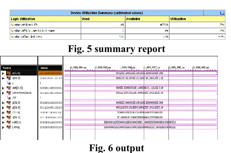
V.RESULTS
Fig. 5 summary report
Fig. 6 output
VI. CONCLUSION
In this brief, by investigating the relation between the recursion computations, a novel method has been proposed, which is called MSR. The proposed method is applied to the previous ACS architectures then achieves an area-efficient architecture for recursive computations. The proposed architectures achieve, at most 18.1% reduction in complexity, which notably reduces the complexity of the whole MAP core of the turbo decoder. Furthermore, the proposed method can be also used for higher radix designs to reduce complexity.
VIII. REFERENCES
[1] C. Berrou and A. Glavieux, “Near optimum error correcting coding and decoding: Turbo-codes,”
IEEE Trans. Commun., vol. 44, no. 10, pp. 1261–
1271, Oct. 1996.
[2] S. Belfanti, C. Roth, M. Gautschi, C. Benkeser, and Q. Huang, “A 1 Gbps LTE-advanced turbo-decoder ASIC in 65 nm CMOS,” in Proc. VLSIC
Symp., Jun. 2013, pp. C284–C285.
[3] L. Bahl, J. Cocke, F. Jelinek, and J. Raviv, “Optimal decoding of linear codes for minimizing symbol error rate (Corresp.),” IEEE Trans. Inf.
Theory, vol. IT-20, no. 2, pp. 284–287, Mar. 1974.
[4] V. Franz and J. Anderson, “Concatenated decoding with a reducedsearch BCJR algorithm,” IEEE J. Sel. Areas Commun., vol. 16, no. 2, pp. 186–195, Feb. 1998.
[5] J. Woodard and L. Hanzo, “Comparative study of turbo decoding techniques: An overview,” IEEE
Trans. Veh. Technol., vol. 49, no. 6, pp. 2208–2233,
Nov. 2000.
[6] C. Studer, “Iterative MIMO decoding: Algorithms and VLSI implementation aspects,” Ph.D. dissertation, Dept. Inform. Technol. Elect. Eng., ETH Zurich, Zurich, Switzerland, Jun. 2009. [7] L. Li, R. Maunder, B. Al-Hashimi, and L. Hanzo, “A low-complexity turbo decoder architecture for energy-efficient wireless sensor networks,” IEEE Trans. Very Large Scale Integr. (VLSI) Syst., vol. 21, no. 1, pp. 14–22, Jan. 2013.
[8] G. Fettweis and H. Meyr, “Parallel Viterbi algorithm implementation: Breaking the ACS-bottleneck,” IEEE Trans. Commun., vol. 37, no. 8, pp. 785–790, Aug. 1989.
[9] C. Studer, C. Benkeser, S. Belfanti, and Q. Huang, “Design and implementation of a parallel turbo-decoder ASIC for 3GPP-LTE,” IEEE J. Solid-State Circuits, vol. 46, no. 1, pp. 8–17, Jan. 2011.
1M.RANJITH KUMAR
2